13. ACPI System Management Bus Interface Specification
This section describes the System Management Bus (SMBus) generic address space and the use of this address space to access SMBus devices from AML.
Unlike other address spaces, SMBus operation regions are inherently non-linear, where each offset within an SMBus address space represents a variable-sized (from 0 to 32 bytes) field. Given this uniqueness, SMBus operation regions include restrictions on their field definitions and require the use of an SMBus-specific data buffer for all transactions.
The SMBus interface presented in this section is intended for use with any hardware implementation compatible with the SMBus specification. SMBus hardware is broadly classified as either non-EC-based or EC-based. EC-based SMBus implementations comply with the standard register set defined in ACPI Embedded Controller Interface Specification.
Non-EC SMBus implementations can employ any hardware interface and are typically used for their cost savings when SMBus security is not required. Non-EC-based SMBus implementations require the development of hardware specific drivers for each OS implementation. See Declaring SMBus Host Controller Objects for more information.
Support of the SMBus generic address space by ACPI-compatible operating systems is optional. As such, the Smart Battery System Implementer’s Forum (SBS-IF) has defined an SMBus interface based on a standard set of control methods. This interface is documented in the SMBus Control Method Interface Specification at http://smbus.org/specs/ (or see http://uefi.org/acpi under the heading “Smart Battery System Components and SMBus Specification”).
13.1. SMBus Overview
SMBus is a two-wire interface based upon the I²C protocol. The SMBus is a low-speed bus that provides positive addressing for devices, as well as bus arbitration. For more information, refer to the complete set of SMBus specifications published by the SBS-IF.
13.1.1. SMBus Slave Addresses
Slave addresses are specified using a 7-bit non-shifted notation. For example, the slave address of the Smart Battery Selector device would be specified as 0x0A (1010b), not 0x14 (10100b) as might be found in other documents. These two different forms of addresses result from the format in which addresses are transmitted on the SMBus.
During transmission over the physical SMBus, the slave address is formatted in an 8-bit block with bits 7-1 containing the address and bit 0 containing the read/write bit. ASL code, on the other hand, presents the slave address simply as a 7-bit value making it the responsibility of the OS (driver) to shift the value if needed. For example, the ASL value would have to be shifted left 1 bit before being written to the SMB_ADDR register in the EC based SMBus as described in Address Register, SMB_ADDR.
13.1.2. SMBus Protocols
There are seven possible command protocols for any given SMBus slave device, and a device may use any or all of the protocols to communicate. The protocols and associated access type indicators are listed below. Notice that the protocols values are similar to those defined for the EC-based SMBus in Protocol Register, SMB_PRTCL except that protocol pairs (for example, Read Byte, Write Byte) have been joined.
Value |
Type |
Description |
|---|---|---|
0x02 |
SMBQuick |
SMBus Read/Write Quick Protocol |
0x04 |
SMBSendReceive |
SMBus Send/Receive Byte Protocol |
0x06 |
SMBByte |
SMBus Read/Write Byte Protocol |
0x08 |
SMBWord |
SMBus Read/Write Word Protocol |
0x0A |
SMBBlock |
SMBus Read/Write Block Protocol |
0x0C |
SMBProcessCall |
SMBus Process Call Protocol |
0x0D |
SMBBlockProcessCall |
SMBus Write Block-Read Block Process Call Protocol |
All other protocol values are reserved.
Notice that bit 7 of the protocol value is used by this interface to indicate to the SMB-HC whether or not packet error checking (PEC) should be employed for a transaction. Packet error checking is described in section 7.4 of the System Management Bus Specification, Version 1.1. This highly desirable capability improves the reliability and robustness of SMBus communications.
The bit encoding of the protocol value is shown below. For example, the value 0x86 would be used to specify the PEC version of the SMBus Read/Write Byte protocol.
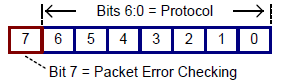
Fig. 13.1 Bit Encoding Example
Notice that bit 0 of the protocol value is always zero (even number hexadecimal values). In a manner similar to the slave address, software that implements the SMBus interface is responsible for setting this bit to indicate whether the transaction is a read (for example, Read Byte) or write (for example, Write Byte) operation.
For example, software implanting this interface for EC-SMBus segments would set bit 0 for read transactions. For the SMBByte protocol (0x06), this would result in the value 0x07 being placed into the SMB_PRTCL register (or 0x87 if PEC is requested) for write transactions.
13.1.3. SMBus Status Codes
The use of status codes helps AML determine whether an SMBus transaction was successful. In general, a status code of zero indicates success, while a non-zero value indicates failure. The SMBus interface uses the same status codes defined for the EC-SMBus (see Status Register, SMB_STS).
13.1.4. SMBus Command Values
SMBus devices may optionally support up to 256 device-specific commands. For these devices, each command value supported by the device is modeled by this interface as a separate virtual register. Protocols that do not transmit a command value (for example, Read/Write Quick and Send/Receive Byte) are modeled using a single virtual register (with a command value = 0x00).
13.2. Accessing the SMBus from ASL Code
The following sections demonstrate how to access and use the SMBus from ASL code.
13.2.1. Declaring SMBus Host Controller Objects
EC-based SMBus 1.0-compatible HCs should be modeled in the ACPI namespace as described in Defining an Embedded Controller Device in ACPI Namespace , “Defining an Embedded Controller SMBus Host Controller in ACPI Namespace.” An example definition is given below. Using the HID value “ACPI0001” identifies that this SMB-HC is implemented on an embedded controller using the standard SMBus register set defined in SMBus Host Controller Interface via Embedded Controller.
Device (SMB0)
{
   Name(_HID, "ACPI0001") // EC-based SMBus 1.0 compatible Host Controller
   Name(_EC, 0x2030) // EC offset 0x20, query bit 0x30
      :
}
EC-based SMBus 2.0-compatible host controllers should be defined similarly in the namespace as follows:
Device (SMB0)
{
   Name(_HID, "ACPI0005") // EC-based SMBus 2.0 compatible Host Controller
   Name(_EC, 0x2030) // EC offset 0x20, query bit 0x30
      :
}
Non-EC-based SMB-HCs should be modeled in a manner similar to the EC-based SMBus HC. An example definition is given below. These devices use a vendor-specific hardware identifier (HID) to specify the type of SMB-HC (do not use “ACPI0001” or “ACPI0005”). Using a vendor-specific HID allows the correct software to be loaded to service this segment’s SMBus address space.
Device(SMB0)
{
   Name(_HID, "<vendor-specific hid>") // Vendor-Specific HID
      :
}
Regardless of the type of hardware, some OS software element (for example, the SMBus HC driver) must register with OSPM to support all SMBus operation regions defined for the segment. This software allows the generic SMBus interface defined in this section to be used on a specific hardware implementation by translating between the conceptual (for example, SMBus address space) and physical (for example, process of writing/reading registers) models. Because of this linkage, SMBus operation regions must be defined immediately within the scope of the corresponding SMBus device.
13.2.2. Declaring SMBus Devices
The SMBus, as defined by the SMBus Specifications <http://smbus.org/specs/>, is not an enumerable bus. As a result, an SMBus 1.0-compatible SMB-HC driver cannot discover child devices on the SMBus and load the appropriate corresponding device drivers. As such, SMBus 1.0-compatible devices are declared in the ACPI namespace, in like manner to other motherboard devices, and enumerated by OSPM.
The SMBus 2.0 specification adds mechanisms enabling device enumeration on the bus while providing compatibility with existing devices. ACPI defines and associates the “ACPI0005” HID value with an EC-based SMBus 2.0-compatible host controller. OSPM will enumerate SMBus 1.0-compatible devices when declared in the namespace under an SMBus 2.0-compatible host controller.
The responsibility for the definition of ACPI namespace objects, required by an SMBus 2.0-compatible host controller driver to enumerate non-bus-enumerable devices, is relegated to the Smart Battery System Implementers Forum. See the SMBus Specifications at the link mentioned above.
Starting in ACPI 2.0, _ADR is used to associate SMBus devices with their lowest SMBus slave address.
13.2.3. Declaring SMBus Operation Regions
Each SMBus operation region definition identifies a single SMBus slave address. Operation regions are defined only for those SMBus devices that need to be accessed from AML. As with other regions, SMBus operation regions are only accessible via the Field term (see Declaring SMBus Devices).
This interface models each SMBus device as having a 256-byte linear address range. Each byte offset within this range corresponds to a single command value (for example, byte offset 0x12 equates to command value 0x12), with a maximum of 256 command values. By doing this, SMBus address spaces appear linear and can be processed in a manner similar to the other address space types.
The syntax for the OperationRegion term (from OperationRegion (Declare Operation Region)) is described below.
OperationRegion (
   RegionName,             // NameString
   RegionSpace,            // RegionSpaceKeyword
   Offset,                 // TermArg=>Integer
   Length                  // TermArg=>Integer
)
Where:
RegionName specifies a name for this slave device (for example, “SBD0”).
RegionSpace must be set to SMBus (operation region type value 0x04).
Offset is a word-sized value specifying the slave address and initial command value offset for the target device. The slave address is stored in the high byte and the command value offset is stored in the low byte. For example, the value 0x4200 would be used for an SMBus device residing at slave address 0x42 with an initial command value offset of zero (0).
Length is set to the 0x100 (256), representing the maximum number of possible command values, for regions with an initial command value offset of zero (0). The difference of these two values is used for regions with non-zero offsets. For example, a region with an Offset value of 0x4210 would have a corresponding Length of 0xF0 (0x100 minus 0x10).
For example, the Smart Battery Subsystem (illustrated below) consists of the Smart Battery Charger at slave address 0x09, the Smart Battery System Manager at slave address 0x0A, and one or more batteries (multiplexed) at slave address 0x0B. (Notice that Figure 13-2 represents the logical connection of a Smart Battery Subsystem. The actual physical connections of the Smart Battery(s) and the Smart Battery Charger are made through the Smart Battery System Manager.) All devices support the Read/Write Word protocol. Batteries also support the Read/Write Block protocol.
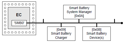
Fig. 13.2 Smart Battery Subsystem Devices
The following ASL code shows the use of the OperationRegion term to describe these SMBus devices:
Device (SMB0)
{
   Name(_HID, "ACPI0001") // EC-SMBus Host Controller
   Name(_EC, 0x2030) // EC offset 0x20, query bit 0x30

OperationRegion(SBC0, SMBus, 0x0900, 0x100)      // Smart Battery Charger
OperationRegion(SBS0, SMBus, 0x0A00, 0x100)      // Smart Battery Selector
OperationRegion(SBD0, SMBus, 0x0B00, 0x100)      // Smart Battery Device(s)
   :
}
Notice that these operation regions in this example are defined within the immediate context of the ‘owning’ EC-SMBus device. Each definition corresponds to a separate slave address (device), and happens to use an initial command value offset of zero (0).
13.2.4. Declaring SMBus Fields
As with other regions, SMBus operation regions are only accessible via the Field term. Each field element is assigned a unique command value and represents a virtual register on the targeted SMBus device.
The syntax for the Field term (from Event (Declare Event Synchronization Object)) is described below.
Field(
   RegionName,           // NameString=>OperationRegion
   AccessType,           // AccessTypeKeyword
   LockRule,             // LockRuleKeyword
   UpdateRule            // UpdateRuleKeyword - *ignored*
) {FieldUnitList}
Where:
RegionName specifies the operation region name previously defined for the device.
AccessType must be set to BufferAcc. This indicates that access to field elements will be done using a region-specific data buffer. For this access type, the field handler is not aware of the data buffer’s contents which may be of any size. When a field of this type is used as the source argument in an operation it simply evaluates to a buffer. When used as the destination, however, the buffer is passed bi-directionally to allow data to be returned from write operations. The modified buffer then becomes the execution result of that operation. This is slightly different than the normal case in which the execution result is the same as the value written to the destination. Note that the source is never changed, since it could be a read only object (see Declaring and Using an SMBus Data Buffer and ASL Opcode Terms).
LockRule indicates if access to this operation region requires acquisition of the Global Lock for synchronization. This field should be set to Lock on system with firmware that may access the SMBus, and NoLock otherwise.
UpdateRule is not applicable to SMBus operation regions since each virtual register is accessed in its entirety. This field is ignored for all SMBus field definitions.
SMBus operation regions require that all field elements be declared at command value granularity. This means that each virtual register cannot be broken down to its individual bits within the field definition.
Access to sub-portions of virtual registers can be done only outside of the field definition. This limitation is imposed both to simplify the SMBus interface and to maintain consistency with the physical model defined by the SMBus specification.
SMBus protocols are assigned to field elements using the AccessAs term within the field definition. The syntax for this term (from ASL Root and Secondary Terms) is described below.
AccessAs(
   AccessType, //AccessTypeKeyword
   AccessAttribute //Nothing \| ByteConst \| AccessAttribKeyword
)
Where:
AccessType must be set to BufferAcc.
AccessAttribute indicates the SMBus protocol to assign to command values that follow this term. See SMBus Protocols for a listing of the SMBus protocol types and values.
An AccessAs term must appear as the first entry in a field definition to set the initial SMBus protocol for the field elements that follow. A maximum of one SMBus protocol may be defined for each field element. Devices supporting multiple protocols for a single command value can be modeled by specifying multiple field elements with the same offset (command value), where each field element is preceded by an AccessAs term specifying an alternate protocol.
For example, the register at command value 0x08 for a Smart Battery device (illustrated below) represents a word value specifying the battery temperature (in degrees Kelvin), while the register at command value 0x20 represents a variable-length (0 to 32 bytes) character string specifying the name of the company that manufactured the battery.
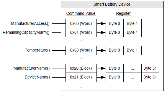
Fig. 13.3 Smart Battery Device Virtual Registers
The following ASL code shows the use of the OperationRegion, Field, AccessAs, and Offset terms to represent these Smart Battery device virtual registers:
OperationRegion(SBD0, SMBus, 0x0B00, 0x0100)
Field(SBD0, BufferAcc, NoLock, Preserve)
{
   AccessAs(BufferAcc, SMBWord)   // Use the SMBWord protocol for the following...
   MFGA, 8,                       // ManufacturerAccess() [command value 0x00]
   RCAP, 8,                       // RemainingCapacityAlarm() [command value 0x01]
   Offset(0x08)                   // Skip to command value 0x08...
   BTMP, 8,                       // Temperature() [command value 0x08]
   Offset(0x20)                   // Skip to command value 0x20...
   AccessAs(BufferAcc, SMBBlock)  // Use the SMBBlock protocol for the following...
   MFGN, 8,                       // ManufacturerName() [command value 0x20]
   DEVN, 8                        // DeviceName() [command value 0x21]
}
Notice that command values are equivalent to the field element’s byte offset (for example, MFGA=0, RCAP=1, BTMP=8). The AccessAs term indicates which SMBus protocol to use for each command value.
13.2.5. Declaring and Using an SMBus Data Buffer
The use of a data buffer for SMBus transactions allows AML to receive status and data length values, as well as making it possible to implement the Process Call protocol. As previously mentioned, the BufferAcc access type is used to indicate to the field handler that a region-specific data buffer will be used.
For SMBus operation regions, this data buffer is defined as a fixed-length 34-byte buffer that, if represented using a ‘C’-styled declaration, would be modeled as follows:
typedef struct
{
   BYTE Status;               // Byte 0 of the data buffer
   BYTE Length;               // Byte 1 of the data buffer
   BYTE[32] Data;             // Bytes 2 through 33 of the data buffer
}
Where:
Status (byte 0) indicates the status code of a given SMBus transaction. See SMBus Status Codes for more information.
Length (byte 1) specifies the number of bytes of valid data that exists in the data buffer. Use of this field is only defined for the Read/Write Block protocol, where valid Length values are 0 through 32. For other protocols–where the data length is implied by the protocol–this field is reserved.
Data (bytes 33-2) represents a 32-byte buffer, and is the location where actual data is stored.
For example, the following ASL shows the use of the SMBus data buffer for performing transactions to a Smart Battery device. This code is based on the example ASL presented in Declaring SMBus Fields which lists the operation region and field definitions for the Smart Battery device.
/* Create the SMBus data buffer */
Name(BUFF, Buffer(34){})            // Create SMBus data buffer as BUFF
CreateByteField(BUFF, 0x00, OB1)    // OB1 = Status (Byte)
CreateByteField(BUFF, 0x01, OB2)    // OB2 = Length (Byte)
CreateWordField(BUFF, 0x02, OB3)    // OB3 = Data (Word - Bytes 2 & 3)
CreateField(BUFF, 0x10, 256, OB4)   // OB4 = Data (Block - Bytes 2-33)

/* Read the battery temperature */
Store(BTMP, BUFF) // Invoke Read Word transaction
If(LEqual(OB1, 0x00)) // Successful?
{
                                    // OB3 = Battery temperature in 1/10th degrees Kelvin
}

/* Read the battery manufacturer name */
Store(MFGN, BUFF)                   // Invoke Read Block transaction
If(LEqual(OB1, 0x00))               // Successful?
{
                                    // OB2 = Length of the manufacturer name
                                    // OB4 = Manufacturer name (as a counted string)
}
Notice the use of the CreateField primitives to access the data buffer’s sub-elements (Status, Length, and Data), where Data (bytes 33-2) is ‘typecast’ as both word (OB3) and block (OB4) data.
The example above demonstrates the use of the Store() operator to invoke a Read Block transaction to obtain the name of the battery manufacturer. Evaluation of the source operand (MFGN) results in a 34-byte buffer that gets copied by Store() to the destination buffer (BUFF).
Capturing the results of a write operation, for example to check the status code, requires an additional Store() operator, as shown below.
Store(Store(BUFF, MFGN), BUFF)      // Invoke Write Block transaction
If(LEqual(OB1, 0x00)) {...}         // Transaction successful?
Note that the outer Store() copies the results of the Write Block transaction back into BUFF. This is the nature of BufferAcc’s bi-directionality described in Declaring SMBus Fields. It should be noted that storing (or parsing) the result of an SMBus Write transaction is not required although useful for ascertaining the outcome of a transaction.
SMBus Process Call protocols require similar semantics due to the fact that only destination operands are passed bi-directionally. These transactions require the use of the double-Store() semantics to properly capture the return results.
13.3. Using the SMBus Protocols
This section provides information and examples on how each of the SMBus protocols can be used to access SMBus devices from AML.
13.3.1. Read/Write Quick (SMBQuick)
The SMBus Read/Write Quick protocol (SMBQuick) is typically used to control simple devices using a device-specific binary command (for example, ON and OFF). Command values are not used by this protocol and thus only a single element (at offset 0) can be specified in the field definition. This protocol transfers no data.
The following ASL code illustrates how a device supporting the Read/Write Quick protocol should be accessed:
OperationRegion(SMBD, SMBus, 0x4200, 0x100) // SMBus device at slave address 0x42
Field(SMBD, BufferAcc, NoLock, Preserve)
{
    AccessAs(BufferAcc, SMBQuick)           // Use the SMBus Read/Write Quick protocol
    FLD0, 8                                 // Virtual register at command value 0.
}

/* Create the SMBus data buffer */

Name(BUFF, Buffer(34){})                    // Create SMBus data buffer as BUFF
CreateByteField(BUFF, 0x00, OB1)            // OB1 = Status (Byte)

/* Signal device (e.g. OFF) */
Store(FLD0, BUFF)                           // Invoke Read Quick transaction
If(LEqual(OB1, 0x00)) {...}                 // Successful?

/* Signal device (e.g. ON) */
Store(BUFF, FLD0) // Invoke Write Quick transaction
In this example, a single field element (FLD0) at offset 0 is defined to represent the protocol’s read/write bit. Access to FLD0 will cause an SMBus transaction to occur to the device. Reading the field results in a Read Quick, and writing to the field results in a Write Quick. In either case data is not transferred–access to the register is simply used as a mechanism to invoke the transaction.
13.3.2. Send/Receive Byte (SMBSendReceive)
The SMBus Send/Receive Byte protocol (SMBSendReceive) transfers a single byte of data. Like Read/Write Quick, command values are not used by this protocol and thus only a single element (at offset 0) can be specified in the field definition.
The following ASL code illustrates how a device supporting the Send/Receive Byte protocol should be accessed:
OperationRegion(SMBD, SMBus, 0x4200, 0x100) // SMBus device at slave address 0x42
Field(SMBD, BufferAcc, NoLock, Preserve)
{
AccessAs(BufferAcc, SMBSendReceive)    // Use the SMBus Send/Receive Byte protocol
FLD0, 8                                // Virtual register at command value 0.
}

// Create the SMBus data buffer

Name(BUFF, Buffer(34){})               // Create SMBus data buffer as BUFF
CreateByteField(BUFF, 0x00, STAT)      // STAT = Status (Byte)
CreateByteField(BUFF, 0x02, DATA)      // DATA = Data (Byte)

// Receive a byte of data from the device

Store(FLD0, BUFF)                      // Invoke a Receive Byte transaction

If(LEqual(STAT, 0x00))                 // Successful?

{
                                       // DATA = Received byte...
}

// Send the byte '0x16' to the device
Store(0x16, DATA)                      // Save 0x16 into the data buffer
Store(BUFF, FLD0)                      // Invoke a Send Byte transaction
In this example, a single field element (FLD0) at offset 0 is defined to represent the protocol’s data byte. Access to FLD0 will cause an SMBus transaction to occur to the device. Reading the field results in a Receive Byte, and writing to the field results in a Send Byte.
13.3.3. Read/Write Byte (SMBByte)
The SMBus Read/Write Byte protocol (SMBByte) also transfers a single byte of data. But unlike Send/Receive Byte, this protocol uses a command value to reference up to 256 byte-sized virtual registers.
The following ASL code illustrates how a device supporting the Read/Write Byte protocol should be accessed:
OperationRegion(SMBD, SMBus, 0x4200, 0x100)  // SMBus device at slave address 0x42
Field(SMBD, BufferAcc, NoLock, Preserve)
{
    AccessAs(BufferAcc, SMBByte)             // Use the SMBus Read/Write Byte protocol
    FLD0, 8,                                 // Virtual register at command value 0.
    FLD1, 8,                                 // Virtual register at command value 1.
    FLD2, 8                                  // Virtual register at command value 2.
}

                                             // Create the SMBus data buffer
Name(BUFF, Buffer(34){}) // Create SMBus data buffer as BUFF
CreateByteField(BUFF, 0x00, STAT) // STAT = Status (Byte)
CreateByteField(BUFF, 0x02, DATA) // DATA = Data (Byte)

// Read a byte of data from the device using command value 1
Store(FLD1, BUFF) // Invoke a Read Byte transaction
If(LEqual(STAT, 0x00)) // Successful?
{
                                             // DATA = Byte read from FLD1...
}

// Write the byte '0x16' to the device using command value 2
Store(0x16, DATA)                            // Save 0x16 into the data buffer
Store(BUFF, FLD2)                            // Invoke a Write Byte transaction
In this example, three field elements (FLD0, FLD1, and FLD2) are defined to represent the virtual registers for command values 0, 1, and 2. Access to any of the field elements will cause an SMBus transaction to occur to the device. Reading FLD1 results in a Read Byte with a command value of 1, and writing to FLD2 results in a Write Byte with command value 2.
13.3.4. Read/Write Word (SMBWord)
The SMBus Read/Write Word protocol (SMBWord) transfers 2 bytes of data. This protocol also uses a command value to reference up to 256 word-sized virtual device registers.
The following ASL code illustrates how a device supporting the Read/Write Word protocol should be accessed:
OperationRegion(SMBD, SMBus, 0x4200, 0x100)  // SMBus device at slave address 0x42
Field(SMBD, BufferAcc, NoLock, Preserve)
{
    AccessAs(BufferAcc, SMBWord)         // Use the SMBus Read/Write Word protocol
    FLD0, 8,                             // Virtual register at command value 0.
    FLD1, 8,                             // Virtual register at command value 1.
    FLD2, 8                              // Virtual register at command value 2.
}

                                         // Create the SMBus data buffer
Name(BUFF, Buffer(34){})                 // Create SMBus data buffer as BUFF
CreateByteField(BUFF, 0x00, STAT)        // STAT = Status (Byte)
CreateWordField(BUFF, 0x02, DATA)        // DATA = Data (Word)

// Read two bytes of data from the device using command value 1
Store(FLD1, BUFF)                        // Invoke a Read Word transaction
If(LEqual(STAT, 0x00))                   // Successful?
{
                                         // DATA = Word read from FLD1...
}

// Write the word '0x5416' to the device using command value 2
Store(0x5416, DATA)                      // Save 0x5416 into the data buffer
Store(BUFF, FLD2)                        // Invoke a Write Word transaction
In this example, three field elements (FLD0, FLD1, and FLD2) are defined to represent the virtual registers for command values 0, 1, and 2. Access to any of the field elements will cause an SMBus transaction to occur to the device. Reading FLD1 results in a Read Word with a command value of 1, and writing to FLD2 results in a Write Word with command value 2.
Notice that although accessing each field element transmits a word (16 bits) of data, the fields are listed as 8 bits each. The actual data size is determined by the protocol. Every field element is declared with a length of 8 bits so that command values and byte offsets are equivalent.
13.3.5. Read/Write Block (SMBBlock)
The SMBus Read/Write Block protocol (SMBBlock) transfers variable-sized (0-32 bytes) data. This protocol uses a command value to reference up to 256 block-sized virtual registers.
The following ASL code illustrates how a device supporting the Read/Write Block protocol should be accessed:
OperationRegion(SMBD, SMBus, 0x4200, 0x100) // SMBus device at slave address 0x42
Field(SMBD, BufferAcc, NoLock, Preserve)
{
  AccessAs(BufferAcc, SMBBlock)           // Use the SMBus Read/Write Block protocol
  FLD0, 8,                                // Virtual register at command value 0.
  FLD1, 8,                                // Virtual register at command value 1.
  FLD2, 8                                 // Virtual register at command value 2.
}

// Create the SMBus data buffer
Name(BUFF, Buffer(34){})                  // Create SMBus data buffer as BUFF
CreateByteField(BUFF, 0x00, STAT)         // STAT = Status (Byte)
CreateByteField(BUFF, 0x01, SIZE)         // SIZE = Length (Byte)
CreateField(BUFF, 0x10, 256, DATA)        // DATA = Data (Block)

// Read block data from the device using command value 1
Store(FLD1, BUFF)                         // Invoke a Read Block transaction
If(LEqual(STAT, 0x00))                    // Successful?
{
                                          // SIZE = Size (number of bytes)
                                          // of the block data read from FLD1...
                                          // DATA = Block data read from FLD1...
 }

 // Write the block 'TEST' to the device using command value 2
 Store("TEST", DATA)                       // Save "TEST" into the data buffer
 Store(4, SIZE)                            // Length of valid data in the data buffer
 Store(BUFF, FLD2)                         // Invoke a Write Word transaction
In this example, three field elements (FLD0, FLD1, and FLD2) are defined to represent the virtual registers for command values 0, 1, and 2. Access to any of the field elements will cause an SMBus transaction to occur to the device. Reading FLD1 results in a Read Block with a command value of 1, and writing to FLD2 results in a Write Block with command value 2.
13.3.6. Word Process Call (SMBProcessCall)
The SMBus Process Call protocol (SMBProcessCall) transfers 2 bytes of data bi-directionally (performs a Write Word followed by a Read Word as an atomic transaction). This protocol uses a command value to reference up to 256 word-sized virtual registers.
The following ASL code illustrates how a device supporting the Process Call protocol should be accessed:
OperationRegion(SMBD, SMBus, 0x4200, 0x100) // SMBus device at slave address 0x42
Field(SMBD, BufferAcc, NoLock, Preserve)
{
    AccessAs(BufferAcc, SMBProcessCall)     // Use the SMBus Process Call protocol
    FLD0, 8,                                // Virtual register at command value 0.
    FLD1, 8,                                // Virtual register at command value 1.
    FLD2, 8                                 // Virtual register at command value 2.
}

// Create the SMBus data buffer
Name(BUFF, Buffer(34){})                    // Create SMBus data buffer as BUFF
CreateByteField(BUFF, 0x00, STAT)           // STAT = Status (Byte)
CreateWordField(BUFF, 0x02, DATA)           // DATA = Data (Word)

// Process Call with input value '0x5416' to the device using command value 1
Store(0x5416, DATA)                         // Save 0x5416 into the data buffer
Store(Store(BUFF, FLD1), BUFF)              // Invoke a Process Call transaction
If(LEqual(STAT, 0x00))                      // Successful?
{
                                            // DATA = Word returned from FLD1...
}
In this example, three field elements (FLD0, FLD1, and FLD2) are defined to represent the virtual registers for command values 0, 1, and 2. Access to any of the field elements will cause an SMBus transaction to occur to the device. Reading or writing FLD1 results in a Process Call with a command value of 1. Notice that unlike other protocols, Process Call involves both a write and read operation in a single atomic transaction. This means that the Data element of the SMBus data buffer is set with an input value before the transaction is invoked, and holds the output value following the successful completion of the transaction.
13.3.7. Block Process Call (SMBBlockProcessCall)
The SMBus Block Write-Read Block Process Call protocol (SMBBlockProcessCall) transfers a block of data bi-directionally (performs a Write Block followed by a Read Block as an atomic transaction). The maximum aggregate amount of data that may be transferred is limited to 32 bytes. This protocol uses a command value to reference up to 256 block-sized virtual registers.
The following ASL code illustrates how a device supporting the Process Call protocol should be accessed:
OperationRegion(SMBD, SMBus, 0x4200, 0x100)  // SMbus device at slave address 0x42
Field(SMBD, BufferAcc, NoLock, Preserve)
{
    AccessAs(BufferAcc, SMBBlockProcessCall) // Use the Block Process Call protocol
    FLD0, 8, // Virtual register representing a command value of 0
    FLD1, 8 // Virtual register representing a command value of 1
}

// Create the SMBus data buffer as BUFF
Name(BUFF, Buffer(34)())           // Create SMBus data buffer as BUFF
CreateByteField(BUFF, 0x00, STAT)  // STAT = Status (Byte)
CreateByteField(BUFF, 0x01, SIZE)  // SIZE = Length (Byte)
CreateField(BUFF, 0x10, 256, DATA) // Data (Block)

// Process Call with input value "ACPI" to the device using command value 1

Store("ACPI", DATA)                // Fill in outgoing data
Store(8, SIZE)                     // Length of the valid data
Store(Store(BUFF, FLD1), BUFF)     // Execute the PC
if (LEqual(STAT, 0x00))            // Test the status
{
                                   // BUFF now contains information returned
                                   // from PC
                                   // SIZE now equals size of data returned
}