14. Platform Communications Channel (PCC)
The platform communication channel (PCC) is a generic mechanism for OSPM to communicate with an entity in the platform (e.g. a platform controller, or a Baseboard Management Controller (BMC)). Neither the entity that OSPM communicates with, nor any aspects of the information passed back and forth is defined in this section. That information is defined by the actual interface that that employs PCC register address space as the communication channel.
PCC defines a new address space type (PCC Space, 0xA), which is implemented as one or more independent communications channels, or subspaces.
This chapter is arranged as follows:
The Platform Communications Channel Table and Generic Communications Channel Shared Memory Region provide reference information about the PCCT, and expected data structures used for the Platform Communications Channel.
Doorbell Protocol, Platform Notification, and Referencing the PCC address space describe how communications takes place between the OSPM and the platform over PCC.
The PCC interface is described in the following ACPI system description table.
14.1. Platform Communications Channel Table
Field |
Byte Length |
Byte Offset |
Description |
Header |
|||
Signature |
4 |
0 |
‘PCCT’ Signature for the Platform Communications Channel Table. |
Length |
4 |
4 |
Length, in bytes, of the entire PCCT. |
Revision |
1 |
8 |
2 |
Checksum |
1 |
9 |
Entire table must sum to zero. |
OEMID |
6 |
10 |
OEM ID |
OEM Table ID |
8 |
16 |
For the PCCT, the table ID is the manufacturer model ID. |
OEM Revision |
4 |
24 |
OEM revision of PCCT for supplied OEM Table ID. |
Creator ID |
4 |
28 |
Vendor ID of utility that created the table. For tables containing Definition Blocks, this is the ID for the ASL Compiler. |
Creator Revision |
4 |
32 |
Revision of utility that created the table. For tables containing Definition Blocks, this is the revision for the ASL Compiler. |
Flags |
4 |
36 |
Platform Communications Channel Global flags, described in Platform Communications Channel Global Flags. |
Reserved |
8 |
40 |
Reserved |
PCC Subspace Structure[n] (n = subspace ID) |
– |
48 |
A list of Platform Communications Channel Subspace structures for this platform. This structure is described in the following section. At most 256 subspaces are supported. |
14.1.1. Platform Communications Channel Global Flags
PCC Global Flags |
Bit Length |
Bit Offset |
Description |
Platform Interrupt |
1 |
0 |
If set, the platform is capable of generating an interrupt to indicate completion of a command. |
Reserved |
31 |
1 |
Must be zero. |
14.1.2. Platform Communications Channel Subspace Structures
PCC Subspaces are described by the PCC Subspace structure in the PCCT table. The subspace ID of a PCC subspace is its index in the array of subspace structures, starting with subspace 0. All subspaces have a common header, followed by a set of type-specific fields:
Field |
Byte Length |
Byte Offset |
Description |
Type |
1 |
0 |
The type of subspace. |
Length |
1 |
1 |
Length of the subspace structure, in bytes. The next subspace structure begins length bytes after the start of this one. |
Type specific fields |
variable |
2 |
See specific subspace types for more details |
This specification defines the following subspaces:
Type 0, the Generic Communications Subspace,
Types 1 to 2, HW-Reduced Communications Subspaces,
Types 3 and 4 are extended PCC subspaces.
Type 5 is the Hardware Register-Based PCC Subspace.
All other subspace types are reserved.
14.1.3. Generic Communications Subspace Structure (type 0)
Field |
Byte Length |
Byte Offset |
Description |
Type |
1 |
0 |
0 (Generic Communications Subspace) |
Length |
1 |
1 |
62 |
Reserved |
6 |
2 |
Reserved |
Base Address |
8 |
8 |
Base Address of the shared memory range, described in Generic Communications Channel Shared Memory Region. |
Memory Length |
8 |
16 |
Length of the memory range. Must be > 8. |
Doorbell Register |
12 |
24 |
Contains the processor relative address, represented in Generic Address Structure format, of the PCC doorbell. Note: Only System I/O space and System Memory space are valid for values for Address_Space_I D. |
Doorbell Preserve |
8 |
36 |
Contains a mask of bits to preserve when writing the doorbell register. |
Doorbell Write |
8 |
44 |
Contains a mask of bits to set when writing the doorbell register. |
Nominal Latency |
4 |
52 |
Expected latency to process a command, in microseconds. |
Maximum Periodic Access Rate |
4 |
56 |
The maximum number of periodic requests that the subspace channel can support, reported in commands per minute. 0 indicates no limitation. |
Minimum Request Turnaround Time |
2 |
60 |
The minimum amount of time that OSPM must wait after the completion of a command before issuing the next command, in microseconds. |
Note
Inaccurate values for the Maximum Periodic Access Rate and Minimum Request Turnaround Time fields can result in punitive side effects for features that rely on the PCC interface. The Platform should report accurate values that allow for maximum channel efficiency while maintaining maximum channel stability.
The Maximum Periodic Access Rate is used by OSPM to determine the maximum rate for periodic evaluation of commands. Infrequent, event driven commands are not restricted by the maximum periodic access rate.
14.1.4. HW-Reduced Communications Subspace Structure (type 1)
The HW-Reduced Communications Subspace is defined in Table 14.5. It is intended for use on HW-Reduced ACPI Platforms, which do not support the SCI. Aside from the interrupt change, and the allowed use of the Functional Fixed HW address space for the Doorbell Register, this subspace is identical to the Generic Communications Subspace described in Section 14.2 and Section 14.5.
Field |
Byte Length |
Byte Offset |
Description |
Type |
1 |
0 |
1 (HW-Reduced Communications Subspace) |
Length |
1 |
1 |
62 |
Platform Interrupt |
4 |
2 |
GSIV of the interrupt used for the PCC platform interrupt for this Subspace. |
Platform Interrupt Flags |
1 |
6 |
Bit [2-7] Reserved
Bit [1] Platform interrupt mode 1: Interrupt is Edge triggered 0: Interrupt is Level triggered
Bit [0] Platform interrupt polarity 1: Interrupt is Active low 0: Interrupt is Active high
|
Reserved |
1 |
7 |
Reserved |
Base Address |
8 |
8 |
Base Address of the shared memory range, described in Generic Communications Channel Shared Memory Region. |
Memory Length |
8 |
16 |
Length of the memory range. Must be > 8. |
Doorbell Register |
12 |
24 |
Contains the processor relative address, represented in Generic Address Structure format, of the PCC doorbell. Note: Only the System I/O, System Memory, and Functional Fixed Hardware spaces are valid for values for Address_Space_I D. |
Doorbell Preserve |
8 |
36 |
Contains a mask of bits to preserve when writing the doorbell register. |
Doorbell Write |
8 |
44 |
Contains a mask of bits to set when writing the doorbell register. |
Nominal Latency |
4 |
52 |
Expected latency to process a command, in microseconds. |
Maximum Periodic Access Rate |
4 |
56 |
The maximum number of periodic requests that the subspace channel can support, reported in commands per minute. 0 indicates no limitation. |
Minimum Request Turnaround Time |
2 |
60 |
The minimum amount of time that OSPM must wait after the completion of a command before issuing the next command, in microseconds. |
Note
Inaccurate values for the Maximum Periodic Access Rate and Minimum Request Turnaround Time fields can result in punitive side effects for features that rely on the PCC interface. The Platform should report accurate values that allow for maximum channel efficiency while maintaining maximum channel stability.
The Maximum Periodic Access Rate is used by OSPM to determine the maximum rate for periodic evaluation of commands. Infrequent, event driven commands are not restricted by the maximum periodic access rate.
Type 1 subspaces do not support a level triggered platform interrupt as no method is provided to clear the interrupt. Where level interrupts are required, type 2 or type 3 subspaces should be used.
14.1.5. HW-Reduced Communications Subspace Structure (type 2)
The HW-Reduced Communications Subspace is defined below in Table 14.6. This is intended for use on HW-Reduced ACPI Platforms, which require read-modify-write sequence to acknowledge Platform Interrupt. Aside from three Platform Ack fields at the bottom of the table, this subspace is identical to HW-Reduced Communications Subspace Structure (type 1) described above.
Field |
Byte Length |
Byte Offset |
Description |
Type |
1 |
0 |
2 (HW-Reduced Communications Subspace) |
Length |
1 |
1 |
90 |
Platform Interrupt |
4 |
2 |
GSIV of the interrupt used for the PCC platform interrupt for this Subspace. |
Platform Interrupt Flags |
1 |
6 |
Bit [2-7] Reserved
Bit [1] Platform interrupt mode 1: Interrupt is Edge triggered 0: Interrupt is Level triggered
Bit [0] Platform interrupt polarity 1: Interrupt is Active low 0: Interrupt is Active high
|
Reserved |
1 |
7 |
Reserved |
Base Address |
8 |
8 |
Base Address of the shared memory range, described in Generic Communications Channel Shared Memory Region. |
Memory Length |
8 |
16 |
Length of the memory range. Must be > 8. |
Doorbell Register |
12 |
24 |
Contains the processor relative address, represented in Generic Address Structure format, of the PCC doorbell. Note: Only the System I/O, System Memory, and Functional Fixed Hardware spaces are valid for values for Address_Space_I D. |
Doorbell Preserve |
8 |
36 |
Contains a mask of bits to preserve when writing the doorbell register. |
Doorbell Write |
8 |
44 |
Contains a mask of bits to set when writing the doorbell register. |
Nominal Latency |
4 |
52 |
Expected latency to process a command, in microseconds. |
Maximum Periodic Access Rate |
4 |
56 |
The maximum number of periodic requests that the subspace channel can support, reported in commands per minute. 0 indicates no limitation. |
Minimum Request Turnaround Time |
2 |
60 |
The minimum amount of time that OSPM must wait after the completion of a command before issuing the next command, in microseconds. |
Platform Interrupt Ack Register |
12 |
62 |
Contains the processor relative address, represented in Generic Address Structure format, of the platform interrupt ack register. Note: Only the System I/O, System Memory, and Functional Fixed Hardware spaces are valid for values for Address_Space_I D. |
Platform Interrupt Ack Preserve |
8 |
74 |
Contains a mask of bits to preserve when writing the platform interrupt ack register. |
Platform Interrupt Ack Write |
8 |
82 |
Contains a mask of bits to set when writing the platform interrupt ack register. |
Note
Inaccurate values for the Maximum Periodic Access Rate and Minimum Request Turnaround Time fields can result in punitive side effects for features that rely on the PCC interface. The Platform should report accurate values that allow for maximum channel efficiency while maintaining maximum channel stability.
The Maximum Periodic Access Rate is used by OSPM to determine the maximum rate for periodic evaluation of commands. Infrequent, event driven commands are not restricted by the maximum periodic access rate.
14.1.6. Extended PCC subspaces (types 3 and 4)
Extended PCC communication subspaces are of two types:
Type 3 Initiator subspace: used by the OSPM to communicate with the platform.
Type 4 Responder subspace: Used by the platform to send asynchronous notifications to the OSPM.
Initiator subspaces are not substantially different to type 0,1, or 2 subspaces, the most notable difference is that a type 3 Initiator subspace does not support asynchronous notifications. Responder subspaces, type 4, provide those notifications, and cannot be used by the OSPM to send messages to the platform. Together an Initiator and Responder pair create a bidirectional interface between the OSPM and the platform.
The format for PCCT entries describing Initiator (type 3), and Responder (type 4) subspaces is shown in the following table.
Field |
Byte Length |
Byte Offset |
Description |
Type |
1 |
0 |
3 - Initiator subspace 4 - Responder subspace |
Length |
1 |
1 |
164 |
Platform Interrupt |
4 |
2 |
GSIV of an interrupt triggered by the platform: For Initiator subspaces (type 3) this is raised when a command is completed on this subspace. For Responder subspaces (type 4) this is raised when platform sends a notification. For a Initiator subspace, this field is ignored if the platform interrupt flag in Table 14.2 is set to zero. If a Responder-subspace is present in the PCCT, then the platform interrupt flag must be set to 1. Note that if interrupts are edge triggered, then each subspace must have its own unique interrupt. If interrupts are level, a GSIV may be shared by multiple subspaces, but each one must have unique Platform interrupt Ack preserve and Ack Set masks. |
Platform Interrupt Flags |
1 |
6 |
Bit 7:2 Reserved
Bit 1: Platform interrupt mode - Set to 1 if interrupt is Edge triggered - Set to 0 if interrupt Level triggered
Bit 0: Platform interrupt polarity - Set to 1 if interrupt is Active low - Set to 0 if interrupt is Active high
|
Reserved |
1 |
7 |
Reserved must be zero |
Base Address |
8 |
8 |
Base Address of the shared memory range, described in the Initiator Responder Communications Channel Shared Memory Region. |
Memory Length |
4 |
16 |
Length of the memory range. Must be >= 16. |
Doorbell Register |
12 |
20 |
Contains the processor relative address, represented in Generic Address Structure (GAS) format, of the PCC doorbell. Note: Only the System I/O, System Memory, and Functional Fixed Hardware spaces are valid values for Address_Space_I D For Responder subspaces this field is optional, if not present the field should just contain zeros. |
Doorbell Preserve |
8 |
32 |
Contains a mask of bits to preserve when writing the doorbell register. |
Doorbell Write |
8 |
40 |
Contains a mask of bits to set when writing the doorbell register. |
Nominal Latency |
4 |
48 |
Expected latency to process a command, in microseconds. This field is only relevant for Initiator subspaces. |
Maximum Periodic Access Rate |
4 |
52 |
The maximum number of periodic requests that the subspace subspace can support, reported in commands per minute. 0 indicates no limitation. This field is only relevant for Initiator subspaces. |
Minimum Request Turnaround Time |
4 |
56 |
The minimum amount of time that OSPM must wait after the completion of a command before issuing the next command, in microseconds. This field is only relevant for Initiator subspaces. |
Platform interrupt Ack Register |
12 |
60 |
Contains the processor relative address, represented in Generic Address Structure (GAS) format, of the platform interrupt acknowledge register. Note: Only the System I/O, System Memory, and Functional Fixed Hardware spaces are valid for values for Address_Space_I D. If the subspace does not support interrupts or the interrupt is edge driven the register may be omitted. A value of 0x0 on all 12 bytes of the GAS structure indicates the register is not present. If the subspace does support interrupts, and these are level, this register must be supplied. And is used to clear the interrupt by using a read, modify, write sequence. |
Platform interrupt Ack Preserve |
8 |
72 |
Contains a mask of bits to preserve when writing the platform interrupt ack register. |
Platform interrupt Ack Set |
8 |
80 |
Contains a mask of bits to set when writing the platform interrupt ack register. |
Reserved |
8 |
88 |
Reserved must be zero |
Command complete check register address |
12 |
96 |
Contains the processor relative address, represented in Generic Address Structure (GAS) format, of the Command complete check register. Note: Only the System I/O, System Memory, and Functional Fixed Hardware spaces are valid for values for Address_Space_I D |
Command complete check mask |
8 |
108 |
Mask to determine whether a command is complete, using the command complete check register. A command is complete if the value of the register when combined through a logical AND with this mask, yields a non-zero value |
Command complete update register address |
12 |
116 |
Contains the processor relative address, represented in Generic Address Structure (GAS) format, of the command complete update register. Note: Only the System I/O, System Memory, and Functional Fixed Hardware spaces are valid for values for Address_Space_I D |
Command complete update preserve mask |
8 |
128 |
Mask of bits to preserve in the command complete update register, when updating command complete in this subspace. |
Command complete update set mask |
8 |
136 |
Mask of bits to set in the command complete update register, when updating command complete in this subspace. For Initiator subspaces the mask must indicate how to clear the command complete bit. For Responder subspaces, the mask must indicate how to set the command complete bit. |
Error status register |
12 |
144 |
Contains the processor relative address, represented in Generic Address Structure (GAS) format, of the Error status register. This field is ignored by the OSPM on Responder channels Note: Only the System I/O, System Memory, and Functional Fixed Hardware spaces are valid for values for Address_Space_I D Note: this register can be the same as the command complete check register. |
Error status mask |
8 |
156 |
The mask contained here can be combined through a logical AND with content of the Error status register to ascertain whether an error occurred in the transmission of the command through the subspace. The logical NOT of this mask is be used to clear the error. The inverted mask is combined through a logical AND with the content of the Error status register, and the result is written back into said register. This field is ignored for Responder channels. |
Note
Inaccurate values for the Maximum Periodic Access Rate and Minimum Request Turnaround Time fields can result in punitive side effects for features that rely on the PCC interface. The Platform should report accurate values that allow for maximum channel efficiency while maintaining maximum channel stability.
Responder subspaces may be used by the platform to send asynchronous notifications to the OSPM. Responder subspace entries in the PCCT share the same format as Initiator subspaces, with the following modifications:
Type is set to 4 - Responder subspace
The doorbell may be zero and if so must be ignored by the OSM. If present, the platform can request that the OSPM writes to the doorbell after it has processed a notification.
A Responder subspace is associated with an Initiator, that is both an Initiator/Responder pair will connect the OSPM to the same processing entity in the platform.
If a Responder subspace is included in the PCCT, then the global Plaform Interrupt flag (see Table 14.2) must be set to 1.
14.1.7. HW Registers based Communications Subspace Structure (Type 5)
Field |
Length (in bytes) |
Offset |
Value |
Type |
1 |
0 |
5 |
Length |
1 |
1 |
Length (includes vendor defined area) |
Version |
2 |
2 |
0x0001 (Version 1 of this PCC definition) |
Base Address |
8 |
4 |
Base Address of the shared memory range, described in Section 14.4 |
Shared Memory Range Length |
8 |
12 |
Length of the shared memory range described in Table 14.14. If this length is zero then based address is ignored. |
Doorbell Register |
12 |
20 |
Contains the processor relative address, represented in Generic Address Structure format, of the PCC doorbell. Note: Only System I/O space and System Memory space are valid for values for Address_Space_ID. |
Doorbell Preserve |
8 |
32 |
Contains a mask of bits to preserve when writing the doorbell register |
Doorbell Write |
8 |
40 |
Contains a mask of bits to set when writing the doorbell register. This is used to send specific commands to the Platform. |
Command Complete Check Register |
12 |
48 |
Contains the processor relative address, represented in Generic Address Structure format, of Command complete Check register. Note: Only System I/O space and System Memory space are valid for values for Address_Space_ID. |
Command Complete Check mask |
8 |
60 |
Contains a mask of bits to query completion status of the previously issued command from the Command Complete Status Register. OS shall do an AND operation with the Command Complete Check Register value. The OS must check the completion status before writing to doorbell register for the next command. If calculated value is 0 then previous operation has been completed. If completion status is not implemented then this mask should be 0. In this case OS shall only wait for Minimum Request Turnaround Time. Note: Command complete check needs be done before writing to doorbell register to avoid any race condition with a previous use of the doorbell register. In addition to that command complete check needs to be done after writing to doorbell register and before reading Status from Error Status Register. |
Error Status Register |
12 |
68 |
Contains the processor relative address, represented in Generic Address Structure format, of Error Status register. Note: Only System I/O space and System Memory space are valid for values for Address_Space_ID. |
Error Status mask |
8 |
80 |
Contains a mask of bits to get error status of the previous command request from Error Status Register. OS shall do an AND operation with Error Status register value. If this mask value is 0 then Error Status register is ignored. Error Status needs to be checked after completion status indicates issued command has been completed. If Command Complete Check is not implemented (means Command Complete Check mask is 0) then wait for Minimum Request Turnaround Time. If the calculated value is zero, then it indicates success. Any other value indicates failure. |
Nominal Latency |
4 |
88 |
Expected latency to process a command, in microseconds. |
Minimum Request Turnaround Time |
4 |
92 |
The minimum amount of time that OSPM must wait after the completion of a command before issuing the next command, in microseconds. |
14.5. Doorbell Protocol
Other than on Responder subspaces, the doorbell is used by OSPM to notify the platform that the shared memory region contains a valid command that is ready to be processed. A doorbell consists of a hardware register that is accessed via I/O or memory mapped I/O, abstracted in the doorbell field of the PCC subspace structure. OSPM rings the doorbell by performing a read/modify/write cycle on the specified register, preserving and setting the bits specified in the preserve and write mask of the PCC subspace structure.
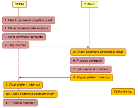
Fig. 14.1 Communication flow of the doorbell protocol
The figure above illustrates the steps that the OPSM takes to send message to the platform over a PCC subspace.
First the OSPM checks that there is no command pending completion on the subspace, indicating that the subspace is free for use. This is done by checking that the command complete bit is set in the status field of the subspace. If the bit is set the subspace is free for use, and the shared memory associated with the subspace is exclusively owned by the OSPM.
The OSPM places a command into the shared memory of the subspace to update the flags, length, command and payload fields (See Generic Communications Channel Shared Memory Region). If the platform indicates support for platform interrupts in the PCCT (See Platform Communications Channel Global Flags), then the OSPM can request that the platform generate an interrupt once it has completed processing the command. This is requested by setting the Notify on completion bit in the flags (See Platform Communications Channel Global Flags and Initiator Responder Communications Channel Flags).
The OSPM then clears the command complete bit. This step transfers ownership of the shared memory to the platform.
OSPM rings the doorbell by performing a read/modify/write cycle on the specified register, preserving and setting the bits specified in the preserve and write mask of the PCC subspace structure.
The management of the command complete bit differs slightly between subspaces of types 0-2 and those of type 3. For the former, the command complete bit is in a status register which follows a specific format described in Generic Communications Channel Status Field. Type 3 subspaces still use a single command complete bit, however allow the platform to dictate the location and format of the register holding it. Therefore, PCCT structures describing type 3 subspaces use masks and an address to describe how to set the bit. Equally, masks are used for describing how to clear the bit. For these subspaces to check if the command complete bit is set, the OSPM combines the content of command complete check register, through a bitwise AND, with the command complete check mask. A non-zero value indicates the command complete bit is set.
Clearing the command complete bit is done through the command complete update register, which can differ in address from the command complete check register. In this case the content of the update register is combined through a bitwise AND with the preserve mask, the result is then combined through a bitwise inclusive OR with the set mask, and that result is written back to the update register.
For subspaces of type 1-3, the command complete bit must be initialized to one, command complete set, prior to OSPM sending a command. On type 0 channels, whether the platform sets command complete when the subspace is initialized is implementation defined. On these subspaces, the OSPM does not have to check for command complete to be set before sending the first command.
The figure Communication flow of the doorbell protocol above illustrates the steps the platform takes when it receives the command:
For robustness the platform might optionally check that command complete bit is clear
Processes the command
Sets the command complete bit
Triggers the platform interrupt indicated by the GSIV of the subspace’s PCCT entry (see Table 14.7). This will only occur if an interrupt has been requested in step 2, and interrupts are supported by the platform. A platform can indicate support for interrupts through the Platform interrupt flag (See Table 14.2)
OSPM can detect command completion either by polling on the command complete bit or via a platform interrupts. When the OSPM detects that the command has completed it proceeds with the following steps:
If necessary clears platform interrupt. This step applies if:
Platform interrupts are supported by the platform on command completion (see Table 14.2).
The interrupt was requested by the OSPM through the Notify on completion flag (see Table 14.9 and Initiator Responder Communications Channel Flags).
The interrupt is described as being a level triggered through the Platform Interrupt flags, and Platform Interrupt Ack register address, and associated masks are provided by the subspace PCCT entry (see table entries for types 2 and 3).
If detecting command completion via interrupt, optionally checks command is complete.
Processes the command response.
To ensure correct operation, it is necessary to ensure that all memory updates performed by the OSPM in step 2 are observable by the platform before step 3 completes. Equally all memory updates performed by the platform in step 6 must be observable by the OSPM before step 7 completes.
Note
For subspace types 0 to 2, all accesses to the Status Field must be made using interlocked operations, by both entities sharing the subspace. Types 3-4 avoid this requirement. This requirement will be removed for subspace types 0 to 2 as part of deprecation of platform async notifications in a future spec revision (See the Platform Notification section below).
14.6. Platform Notification
The following sections describe platform notifications on subspace types 0-2 and types 3-4.
14.6.1. Platform Notification for Subspace Types 0, 1 and 2
The doorbell protocol is a synchronous notification from OSPM to the platform to process a command. If the platform wants to notify OSPM of an event asynchronously, it may set the Platform Interrupt and Platform Notification status bits and issue a Platform Interrupt. OSPM will service the Interrupt, clear the Platform Interrupt and Platform Notification bits, and service the platform notification. The meaning of the platform notification and the steps required to service it are defined by the individual components utilizing the PCC interface.
The platform must wait until OSPM has issued a consumer defined command that serves to notify the platform that OSPM is ready to service Platform Notifications. The command is subspace specific and may not be supported by all subspaces. Platform Notifications must be used in conjunction with an interrupt. Polling for Platform Notifications is not supported.
The platform may not modify any portion of the shared memory region other than the status field when issuing a platform notification.
Platform notifications for subspace types 0, 1, and 2 will be deprecated in a future revision of the specification. Implementers requiring the platform be able to send asynchronous notifications to OSPM should use Initiator/Responder subspaces.
Note: All accesses to the Status Field must be made using interlocked operations, by both entities sharing the subspace. This requirement will be removed for subspace types 0 to 2 as part of deprecation of platform async notifications in a future spec revision.
14.6.2. Platform Notification for Responder PCC subspaces (type 4)
Initiator and subspaces only allow synchronous communication from the OSPM to the platform, and do not use the platform notification mechanism provided for subspaces of types 0 to 2. Instead a Initiator subspace can be paired with a Responder subspace, type 4, which is specifically provided for platform to OSPM communications.
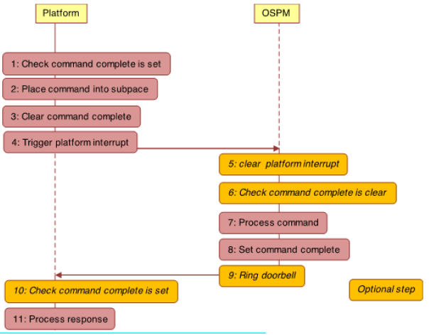
Fig. 14.2 Communication flow for notifications on Responder subspaces
Like type 3 Initiator subspaces, type 4 Responder subspaces include a command complete bit. Responder subspaces are owned by the OSPM by default, and therefore it must set the set the command complete bit when it is ready to receive notifications from the platform.
The flow of communications for a notification is illustrated in the figure Communication flow for notifications on Responder subspaces above. As can be seen the communication flow is very similar to that of an Initiator subspace, shown in the figure Communication flow of the doorbell protocol above, except that the roles of the platform and the OSPM are reversed. The steps are as follows:
First, the platform checks that there no command pending completion on the subspace, indicating that the subspace is free for use. This is done by checking that the command complete bit is set in the status field of the subspace. If the bit is set the subspace is free for use, and the shared memory associated with the subspace is exclusively owned by the platform.
The platform places a notification command into the shared memory in the subspace, updating the flags, length, command and payload fields (See Initiator Responder Communications Channel Shared Memory Region) The platform can request the OSPM rings the doorbell once it has completed processing the notification command by setting the Generate Signal bit in the flags (see Table 14.13).
The platform then clears the command complete bit. This transfers ownership of the shared memory to the OSPM.
The platform raises the platform interrupt indicated by the GSIV of the Responder subspace.
When the OSPM receives the interrupt it executes the following steps:
Clears the platform interrupt. This is required if the interrupt is described as being a level triggered through the Platform Interrupt flags, and Platform Interrupt Ack register address, and associated masks are provided by the subspace PCCT entry (see Table 14.7).
Optionally checks the command complete bit is clear.
Processes the notification command.
Sets the command complete bit using the command complete update register and masks.
Rings the doorbell. This is required if the doorbell ring was requested by the platform in step 2 above. This also requires that the PCCT entry for the subspace has a non-zero doorbell register address.
The platform can check whether a notification has been processed by the OSPM either by polling the command complete bit, or where supported through receiving a doorbell interrupt from the OSPM. When the platform detects that the notification has been processed by the OSPM, the platform takes the following steps:
If polling check command complete is set. If using a doorbell this step is optional.
Processes the command response
The platform must ensure that any writes in step 2, are observable by the OSPM application processors before writes in step 3. Similarly, the OSPM must ensure that any writes in step 7 are observable by the platform before step 8 completes.
Individual protocols that use PCC define the meaning of notifications.
14.7. Referencing the PCC address space
An individual PCC register may be referenced by the Generic Address Structure or in a Generic Register Descriptor by using the Address Space ID PCC (0xA). When using the PCC address space, the Access Size field is redefined to Subspace ID, and identifies which PCC subspace the descriptor refers to.
As an example, the following resource template refers to the field occupying bits 8 through 15 at address 0x30 in PCC subspace 9:
ResourceTemplate()
{
  Register (
  PCC,             //AddressSpaceKeyword
  8,               //RegisterBitWidth
  8,               //RegisterBitOffset
  0x30,            //RegisterAddress
  9                //AccessSize (subspace ID)
  )
}
Note that the PCC address space may not be used in any resource template or register unless the register/resource field explicitly allows the use of the PCC address space.