11. Thermal Management
This chapter describes the ACPI thermal model and specifies the ACPI Namespace objects OSPM uses for thermal management of the platform.
11.1. Thermal Control
ACPI defines interfaces that allow OSPM to be proactive in its system cooling policies. With OSPM in control of the operating environment, cooling decisions can be made based on the system’s application load, the user’s preference towards performance or energy conservation, and thermal heuristics. Graceful shutdown of devices or the entire system at critical heat levels becomes possible as well. The following sections describe the ACPI thermal model and the ACPI Namespace objects available to OSPM to apply platform thermal management policy.
The ACPI thermal model is based around conceptual platform regions called thermal zones that physically contain devices, thermal sensors, and cooling controls. Generally speaking, the entire platform is one large thermal zone, but the platform can be partitioned into several ACPI thermal zones if necessary to enable optimal thermal management.
ACPI Thermal zones are a logical collection of interfaces to temperature sensors, trip points, thermal property information, and thermal controls. Thermal zone interfaces apply either thermal zone wide or to specific devices, including processors, contained within the thermal zone. ACPI defines namespace objects that provide the thermal zone-wide interfaces in Section 11.4. A subset of these objects may also be defined under devices. OS implementations compatible with the ACPI 3.0 thermal model, interface with these objects but also support OS native device driver interfaces that perform similar functions at the device level. This allows the integration of devices with embedded thermal sensors and controls, perhaps not accessible by AML, to participate in the ACPI thermal model through their inclusion in the ACPI thermal zone. OSPM is responsible for applying an appropriate thermal policy when a thermal zone contains both thermal objects and native OS device driver interfaces for thermal control.
Some devices in a thermal zone may be comparatively large producers of thermal load in relation to other devices in the thermal zone. Devices may also have varying degrees of thermal sensitivity. For example, some devices may tolerate operation at a significantly higher temperature than other devices. As such, the platform can provide OSPM with information about the platform’s device topology and the resulting influence of one device’s thermal load generation on another device. This information must be comprehended by OSPM for it to achieve optimal thermal management through the application of cooling controls.
ACPI expects all temperatures to be represented in tenths of degrees. This resolution is deemed sufficient to enable OSPM to perform robust platform thermal management.
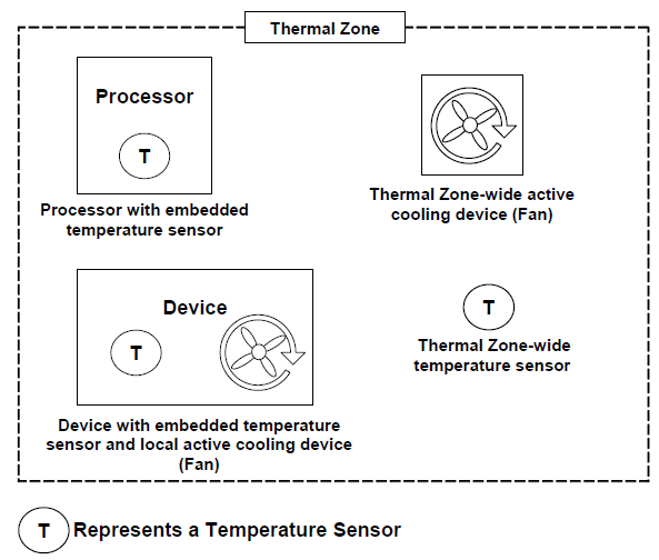
Fig. 11.1 ACPI Thermal Zone
11.1.1. Active, Passive, and Critical Policies
There are three cooling policies that OSPM uses to control the thermal state of the hardware. The policies are active, passive and critical.
Active Cooling. OSPM takes a direct action such as turning on one or more fans. Applying active cooling controls typically consume power and produce some amount of noise, but are able to cool a thermal zone without limiting system performance. Active cooling temperature trip points declare the temperature thresholds OSPM uses to decide when to start or stop different active cooling devices.
Passive Cooling. OSPM reduces the power consumption of devices to reduce the temperature of a thermal zone, such as slowing (throttling) the processor clock. Applying passive cooling controls typically produces no user-noticeable noise. Passive cooling temperature trip points specify the temperature thresholds where OSPM will start or stop passive cooling.
Critical Trip Points. These are threshold temperatures at which OSPM performs an orderly, but critical, shutdown of a device or the entire system. The _HOT object declares the critical temperature at which OSPM may choose to transition the system into the S4 sleeping state, if supported, The _CRT object declares the critical temperature at which OSPM must perform a critical shutdown.
When a thermal zone appears in the ACPI Namespace or when a new device becomes a member of a thermal zone, OSPM retrieves the temperature thresholds (trip points) at which it executes a cooling policy. When OSPM receives a temperature change notification, it evaluates the thermal zone’s temperature interfaces to retrieve current temperature values. OSPM compares the current temperature values against the temperature thresholds. If any temperature is greater than or equal to a corresponding active trip point then OSPM will perform active cooling . If any temperature is greater than or equal to a corresponding passive trip point then OSPM will perform passive cooling. If the _TMP object returns a value greater than or equal to the value returned by the _HOT object then OSPM may choose to transition the system into the S4 sleeping state, if supported. If the _TMP object returns a value greater than or equal to the value returned by the _CRT object then OSPM must shut the system down. Embedded Hot and Critical trip points may also be exposed by individual devices within a thermal zone. Upon passing of these trip points, OSPM must decide whether to shut down the device or the entire system based upon device criticality to system operation. OSPM must also evaluate the thermal zone’s temperature interfaces when any thermal zone appears in the namespace (for example, during system initialization) and must initiate a cooling policy as warranted independent of receipt of a temperature change notification. This allows OSPM to cool systems containing a thermal zone whose temperature has already exceeded temperature thresholds at initialization time.
An optimally designed system that uses several thresholds can notify OSPM of thermal increase or decrease by raising an event every several degrees. This enables OSPM to anticipate thermal trends and incorporate heuristics to better manage the system’s temperature.
To implement a preference towards performance or energy conservation, OSPM can request that the platform change the priority of active cooling (performance) versus passive cooling (energy conservation/silence) by evaluating the _SCP (Set Cooling Policy) object for the thermal zone or a corresponding OS-specific interface to individual devices within a thermal zone.
11.1.2. Dynamically Changing Cooling Temperature Trip Points
The platform or its devices can change the active and passive cooling temperature trip points and notify OSPM to reevaluate the trip point interfaces to establish the new policy threshold settings. The following are the primary uses for this type of thermal notification:
When OSPM changes the platform’s cooling policy from one cooling mode to another.
When a swappable bay device is inserted or removed. A swappable bay is a slot that can accommodate several different devices that have identical form factors, such as a CD-ROM drive, disk drive, and so on. Many mobile PCs have this concept already in place.
After the crossing of an active or passive trip point is signaled to implement hysteresis.
In each situation, OSPM must be notified to re-evaluate the thermal zone’s trip points via the AML code execution of a Notify(thermal_zone, 0x81) statement or via an OS specific interface invoked by device drivers for zone devices participating in the thermal model.
11.1.2.1. OSPM Change of Cooling Policy
When OSPM changes the platform’s cooling policy from one cooling mode to the other, the following occurs:
OSPM notifies the platform of the new cooling mode by running the Set Cooling Policy (_SCP) control method in all thermal zones and invoking the OS-specific Set Cooling Policy interface to all participating devices in each thermal zone.
Thresholds are updated in the hardware and OSPM is notified of the change.
OSPM re-evaluates the active and passive cooling temperature trip points for the zone and all devices in the zone to obtain the new temperature thresholds.
11.1.2.2. Resetting Cooling Temperatures to Adjust to Bay Device Insertion or Removal
The platform can adjust the thermal zone temperature to accommodate the maximum operating temperature of a bay device as necessary. For example:
Hardware detects that a device was inserted into or removed from the bay, updates the temperature thresholds, and then notifies OSPM of the thermal policy change and device insertion events.
OSPM re-enumerates the devices and re-evaluates the active and passive cooling temperature trip points.
11.1.2.3. Resetting Cooling Temperatures to Implement Hysteresis
An OEM can build hysteresis into platform thermal design by dynamically resetting cooling temperature thresholds. For example:
When the temperature increases to the designated threshold, OSPM will turn on the associated active cooling device or perform passive cooling.
The platform resets the threshold value to a lower temperature (to implement hysteresis) and notifies OSPM of the change. Because of this new threshold value, the fan will be turned off at a lower temperature than when it was turned on (therefore implementing a negative hysteresis).
When the temperature hits the lower threshold value, OSPM will turn off the associated active cooling device or cease passive cooling. The hardware will reset _ACx to its original value and notify OSPM that the trip points have once again been altered.
11.1.3. Detecting Temperature Changes
The ability of the platform and its devices to asynchronously notify an ACPI-compatible OS of meaningful changes in the thermal zone’s temperature is a highly desirable capability that relieves OSPM from implementing a poll-based policy and generally results in a much more responsive and optimal thermal policy implementation. Each notification instructs OSPM to evaluate whether a trip point has been crossed and allows OSPM to anticipate temperature trends for the thermal zone.
It is recognized that much of the hardware used to implement thermal zone functionality today is not capable of generating ACPI-visible notifications (SCIs) or only can do so with wide granularity (for example, only when the temperature crosses the critical threshold). In these environments, OSPM must poll the thermal zone’s temperature periodically to implement an effective policy.
While ACPI specifies a mechanism that enables OSPM to poll thermal zone temperature, platform reliance on thermal zone polling is strongly discouraged by this specification. OEMs should design systems that asynchronously notify OSPM whenever a meaningful change in the zone’s temperature occurs - relieving OSPM of the overhead associated with polling. In some cases, embedded controller firmware can overcome limitations of existing thermal sensor capabilities to provide the desired asynchronous notification.
Notice that the _TZP (thermal zone polling) object is used to indicate whether a thermal zone must be polled by OSPM, and if so, a recommended polling frequency. See _TZP (Thermal Zone Polling) for more information.
11.1.3.1. Temperature Change Notifications
Thermal zone-wide temperature sensor hardware that supports asynchronous temperature change notifications does so using an SCI. The AML code that responds to this SCI must execute a Notify(thermal_zone, 0x80) statement to inform OSPM that a meaningful change in temperature has occurred. Alternatively, devices with embedded temperature sensors may signal their associated device drivers and the drivers may use an OS-specific interface to signal OSPM’s thermal policy driver. A device driver may also invoke a device specific control method that executes a Notify(thermal_zone, 0x80) statement. When OSPM receives this thermal notification, it will evaluate the thermal zone’s temperature interfaces to evaluate the current temperature values. OSPM will then compare the values to the corresponding cooling policy trip point values (either zone-wide or device-specific). If the temperature has crossed over any of the policy thresholds, then OSPM will actively or passively cool (or stop cooling) the system, or shut the system down entirely.
Both the number and granularity of thermal zone trip points are OEM-specific. However, it is important to notice that since OSPM can use heuristic knowledge to help cool the system, the more events OSPM receives the better understanding it will have of the system’s thermal characteristic.
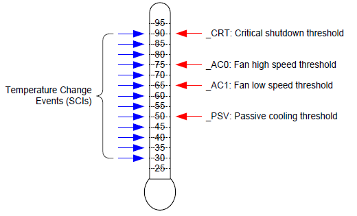
Fig. 11.2 Thermal Events
For example, the simple thermal zone illustrated above includes hardware that will generate a temperature change notification using a 5° Celsius granularity. All thresholds (_PSV, _AC1, _AC0, and _CRT) exist within the monitored range and fall on 5 boundaries. This granularity is appropriate for this system as it provides sufficient opportunity for OSPM to detect when a threshold is crossed as well as to understand the thermal zone’s basic characteristics (temperature trends).
Note: The ACPI specification defines Kelvin as the standard unit for absolute temperature values. All thermal zone objects must report temperatures in Kelvin when reporting absolute temperature values. All figures and examples in this section of the specification use Celsius for reasons of clarity. ACPI allows Kelvin to be declared in precision of 1/10th of a degree (for example, 310.5).
Kelvin is expressed as follows:
11.1.3.2. Polling
Temperature sensor hardware that is incapable of generating thermal change events, or that can do so for only a few thresholds should inform OSPM to implement a poll-based policy. OSPM does this to ensure that temperature changes across threshold boundaries are always detectable.
Polling can be done in conjunction with hardware notifications. For example, thermal zone hardware that only supports a single threshold might be configured to use this threshold as the critical temperature trip point. Assuming that hardware monitors the temperature at a finer granularity than OSPM would, this environment has the benefit of being more responsive when the system is overheating.
A thermal zone advertises the need to be polled by OSPM via the _TZP object. See _TZP (Thermal Zone Polling) for more information.
11.1.4. Active Cooling
Active cooling devices typically consume power and produce some amount of noise when enabled. These devices attempt to cool a thermal zone through the removal of heat rather than limiting the performance of a device to address an adverse thermal condition.
The active cooling interfaces in conjunction with the active cooling lists or the active cooling relationship table (_ART) allow the platform to use an active device that offers varying degrees of cooling capability or multiple cooling devices. The active cooling temperature trip points designate the temperature where Active cooling is engaged or disengaged (depending upon the direction in which the temperature is changing). For thermal zone-wide active cooling controls, the _ALx object evaluates to a list of devices that actively cool the zone or the _ART object evaluates to describe the entire active cooling relationship of various devices. For example:
If a standard single-speed fan is the Active cooling device, then _AC0 evaluates to the temperature where active cooling is engaged and the fan is listed in _AL0.
If the zone uses two independently controlled single-speed fans to regulate the temperature, then _AC0 will evaluate to the maximum cooling temperature using two fans, and _AC1 will evaluate to the standard cooling temperature using one fan.
If a zone has a single fan with a low speed and a high speed, the _AC0 will evaluate to the temperature associated with running the fan at high-speed, and _AC1 will evaluate to the temperature associated with running the fan at low speed. _AL0 and _AL1 will both point to different device objects associated with the same physical fan, but control the fan at different speeds.
If the zone uses two independently controlled multiple-speed fans to regulate the temperature, _AC0 of the target devices evaluates to the temperature at which OSPM will engage fan devices described by the _ART object as needed up to a maximum capability level.
For ASL coding examples that illustrate these points, see Thermal Zone Interface Requirements and Thermal Zone Examples.
11.1.5. Passive Cooling
Passive cooling controls are able to cool a thermal zone without creating noise and without consuming additional power (actually saving power), but do so by decreasing the performance of the devices in the zone .
11.1.5.1. Processor Clock Throttling
The processor passive cooling threshold (_PSV) in conjunction with the processor list (_PSL) allows the platform to indicate the temperature at which a passive control, for example clock throttling, will be applied to the processor(s) residing in a given thermal zone. Unlike other cooling policies, during passive cooling of processors OSPM may take the initiative to actively monitor the temperature in order to cool the platform.
On an ACPI-compatible platform that properly implements CPU throttling, the temperature transitions will be similar to the following figure, in a coolable environment, running a coolable workload:
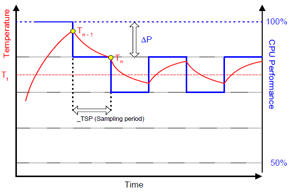
Fig. 11.3 Temperature and CPU Performance Versus Time
The following equation should be used by OSPM to assess the optimum CPU performance change necessary to lower the thermal zone’s temperature:
Equation #1
Where:
The two coefficients _TC1 and _TC2 and the sampling period _TSP are hardware-dependent constants the OEM must supply to OSPM (for more information, see Section 11.4). The _TSP object contains a time interval that OSPM uses to poll the hardware to sample the temperature. Whenever the time value returned by _TSP has elapsed, OSPM will evaluate _TMP to sample the current temperature (shown as Tn in the above equation). Then OSPM will use the sampled temperature and the passive cooling temperature trip point (_PSV) (which is the target temperature Tt) to evaluate the equation for \(\Delta P\). The granularity of \(\Delta P\) is determined by the CPU duty width of the system.
Note: Equation #1 has an implied formula.
Equation #2:
For this equation, whenever Pn-1 + ?P lies outside the range Minimum0-100%, then Pn will be truncated to Minimum0-100%. Minimum% is the _MTL limit, or 0% if _MTL is not defined. For hardware that cannot assume all possible values of Pn between Minimum0 and 100%, a hardware specific mapping function HW is used.
In addition, the hardware mapping function in Equation #2 should be interpreted as follows.
For absolute temperatures:
If the right hand side of Equation #1 is negative, \(HW[\Delta P]\) is rounded to the next available higher setting of frequency.
If the right hand side of Equation #1 is positive, \(HW[\Delta P]\) is rounded to the next available lower setting of frequency.
For relative temperatures:
If the right hand side of Equation #1 is positive, \(HW[\Delta P]\) is rounded to the next available higher setting of frequency.
If the right hand side of Equation #1 is negative, \(HW[\Delta P]\) is rounded to the next available lower setting of frequency.
The calculated Pn becomes Pn-1 during the next sampling period.
For more information about CPU throttling, see Processor Power State C0. A detailed explanation of this thermal feedback equation is beyond the scope of this specification.
11.1.6. Critical Shutdown
When the thermal zone-wide temperature sensor value reaches the threshold indicated by _CRT, OSPM must immediately shut the system down. The system must disable the power either after the temperature reaches some hardware-determined level above _CRT or after a predetermined time has passed. Before disabling power, platform designers should incorporate some time that allows OSPM to run its critical shutdown operation. There is no requirement for a minimum shutdown operation window that commences immediately after the temperature reaches _CRT. This is because:
Temperature might rise rapidly in some systems and slowly on others, depending on casing design and environmental factors.
Shutdown can take several minutes on a server and only a few seconds on a hand-held device.
Because of this indistinct discrepancy and the fact that a critical heat situation is a remarkably rare occurrence, ACPI does not specify a target window for a safe shutdown. It is entirely up to the OEM to build in a safe buffer that it sees fit for the target platform.
11.2. Cooling Preferences
A robust OSPM implementation provides the means for the end user to convey a preference (or a level of preference) for either performance or energy conservation to OSPM. Allowing the end user to choose this preference is most critical to mobile system users where maximizing system run-time on a battery charge often has higher priority over realizing maximum system performance. For example, if a user is taking notes on her PC in a quiet environment, such as a library or a corporate meeting, she may want the system to emphasize passive cooling so that the system operates quietly, even at the cost of system performance.
A user preference towards performance corresponds to the Active cooling mode while a user’s preference towards energy conservation or quiet corresponds to the Passive cooling mode. ACPI defines an interface to convey the cooling mode to the platform. Active cooling can be performed with minimal OSPM thermal policy intervention. For example, the platform indicates through thermal zone parameters that crossing a thermal trip point requires a fan to be turned on. Passive cooling requires OSPM thermal policy to manipulate device interfaces that reduce performance to reduce thermal zone temperature.
Either cooling mode will be activated only when the thermal condition requires it. When the thermal zone is at an optimal temperature level where it does not warrant any cooling, both modes result in a system operating at its maximum potential with all fans turned off.
Thermal zones supporting the Set Cooling Policy interface allow the user to switch the system’s cooling mode emphasis. See _SCP (Set Cooling Policy) for more information.
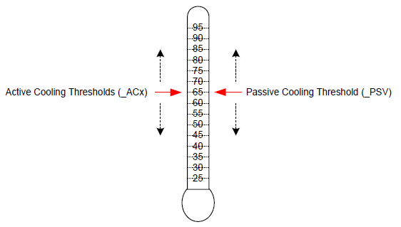
Fig. 11.4 Active and Passive Threshold Values
As illustrated in Active and Passive Threshold Values, the platform must convey the value for each threshold to instruct OSPM to initiate the cooling policies at the desired target temperatures. The platform can emphasize active or passive cooling modes by assigning different threshold values. Generally, if _ACx is set lower than _PSV, then the system emphasizes active cooling. Conversely, if _PSV is set lower than _ACx, then the emphasis is placed on passive cooling.
For example, a thermal zone that includes a processor and one single-speed fan may use _PSV to indicate the temperature value at which OSPM would enable passive cooling and _AC0 to indicate the temperature at which the fan would be turned on. If the value of _PSV is less than _AC0 then the system will favor passive cooling (for example, CPU clock throttling). On the other hand, if _AC0 is less than _PSV the system will favor active cooling (in other words, using the fan). See the figure below for more details.
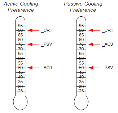
Fig. 11.5 Cooling Preferences
The example on the left enables active cooling (for example, turn on a fan) when OSPM detects the temperature has risen above 50°. If for some reason the fan does not reduce the system temperature, then at 75° OSPM will initiate passive cooling (for example, CPU throttling) while still running the fan. If the temperature continues to climb, OSPM will quickly shut the system down when the temperature reaches 90°C. The example on the right is similar but the _AC0 and _PSV threshold values have been swapped to emphasize passive cooling.
The ACPI thermal model allows flexibility in the thermal zone design. An OEM that needs a less elaborate thermal implementation may consider using only a single threshold (for example, _CRT). Complex thermal implementations can be modeled using multiple active cooling thresholds and devices, or through the use of additional thermal zones.
11.2.1. Evaluating Thermal Device Lists
The Notify(thermal_zone, 0x82) statement is used to inform OSPM that a change has been made to the thermal zone device lists. This thermal event instructs OSPM to re-evaluate the _ALx, _PSL, and _TZD objects.
For example, a system that supports the dynamic insertions of processors might issue this notification to inform OSPM of changes to _PSL following the insertion or removal of a processor. OSPM would re-evaluate all thermal device lists and adjust its policy accordingly.
Notice that this notification can be used with the Notify(thermal_zone, 0x81) statement to inform OSPM to both re-evaluate all device lists and all thresholds.
Alternatively, devices may include the _TZM (Thermal Zone Member) object their device scope to convey their thermal zone association to OSPM. See _TZM (Thermal Zone Member) below for more information.
11.2.2. Evaluating Device Thermal Relationship Information
The Notify(thermal_zone, 0x83) statement is used to inform OSPM that a change has been made to the thermal relationship information. This thermal event instructs OSPM to re-evaluate the _TRT and _ART objects. The thermal influence between devices may change when active cooling moves air across device packages as compared to when only passive cooling controls are applied. Similarly, the active cooling relationship may change as various fans are engaged to actively cool a platform or if user preferences change.
11.2.3. Fan Device Notifications
Notify events of type 0x80 will cause OSPM to evaluate the _FST object to evaluate the fan’s current speed.
11.3. Fan Device
ACPI 1.0 defined a simple fan device that is assumed to be in operation when it is in the D0 state. Thermal zones reference fan device(s) as being responsible primarily for cooling within that zone. Notice that multiple fan devices can be present for any one thermal zone. They might be actual different fans, or they might be used to implement one fan of multiple speeds (for example, by turning both “fans” on the one fan will run full speed).
ACPI 4.0 defines additional fan device interface objects enabling OSPM to perform more robust active cooling thermal control. These objects are summarized (see Table 11.1 below). OSPM requires that all of the objects listed in the table below be defined under a fan device to enable advanced active cooling control. The absence of any of these objects causes OSPM to perform ACPI 1.0 style simple fan control .
The Plug and Play ID of a fan device is PNP0C0B.
Object |
Description |
|---|---|
_FIF |
Returns fan device information. |
_FPS |
Returns a list of supported fan performance states. |
_FSL |
Control method that sets the fan device’s speed level (performance state). |
_FST |
Returns current status information for a fan device. |
While the Fan Device and its associated objects are optional, if the Fan Device is implemented by the platform, all objects listed in the table above are required and must be provided.
11.3.1. Fan Objects
11.3.1.1. _FIF (Fan Information)
The optional _FIF object provides OSPM with fan device capability information.
Arguments:
None
Return Value:
A Package containing the fan device parameters as described in the table below
_FIF evaluation returns a package of the following format:
Package (){
    Revision,                           // Integer
    FineGrainControl,                   // Integer Boolean
    StepSize                            // Integer DWORD
    LowSpeedNotificationSupport         // Integer Boolean
}
Field |
Format |
Description |
|---|---|---|
Revision |
Integer |
Current revision is: 0 |
Fine Grain Control |
Integer (Boolean) |
A non zero value in this field indicates OSPM may evaluate the fan device’s _FSL object with a Level argument value in the range of 0-100, which represents a percentage of maximum speed. A zero value in this field indicates that OSPM may evaluate the fan device’s _FSL object with a Level argument value that is a Control field value from a package in the _FPS object’s package list only. |
Step Size |
Integer (DWORD) |
The recommended minimum step size in percentage points to be used when OSPM performs fine-grained fan speed control. OSPM may utilize the value of this field if the FineGrainControl field is non-zero the value in this field is between 1 and 9. |
Low Speed Notification Support |
Integer (Boolean) |
A non zero value in this field indicates that the platform will issue a Notify (0x80) to the fan device if a low (errant) fan speed is detected. |
If a fan device supports fine-grained control, OSPM may evaluate a fan device’s _FSL object with any Level argument value that is less than or equal to the Control field value specified in the package of the _FPS object’s package list that corresponds to the active cooling trip point that has been exceeded. This capability provides OSPM access to one hundred fan speed settings thus enabling fine-grained fan speed control. The platform uses the StepSize field to help OSPM optimize its fan level selection policy by fine-grained fan speed control. The platform uses the StepSize field to help OSPM optimize its fan level selection policy by indicating recommended increments in the fan speed level value that are appropriate for the fan when one percent increments are not optimal. In the event OSPM’s incremental selections of Level using the StepSize field value do not sum to 100%, OSPM may select an appropriate ending Level increment to reach 100%. OSPM should use the same residual step value first when reducing Level.
11.3.1.2. _FPS (Fan Performance States)
The optional _FPS object evaluates to a variable-length package containing a list of packages that describe the fan device’s performance states. A temperature reading above an active cooling trip point defined by an _ACx object in a thermal zone or above a native active cooling trip point of a device within the thermal zone causes OSPM thermal control to engage the appropriate corresponding fan performance state from the list of fan performance states described by the _FPS object if the fan device is present in the corresponding _ALx device list or if an entry exists for the fan and trip point in the active cooling relationship table (_ART).
OSPM assumes a linear relationship for the acoustic impact and power consumption values between successive entries in the fan performance state list. Notice that the acoustic impact measurement unit (Decibels) is inherently non-linear. As such, the platform should populate _FPS entries as necessary to enable OSPM to achieve optimal results.
Arguments:
None
Return Value:
A variable-length Package containing a Revision ID and a list of Packages that describe the fan device’s performance states as described in the table below.
Return Value Information
Package {
    Revision,             // Integer - Current revision is: 0
    FanPState[0],         // Package
    ....
    FanPState[n]          // Package
}
Each FanPState sub-Package contains the elements described below:
Package ()                // Fan P-State
{
    Control,              // Integer DWORD
    TripPoint,            // Integer DWORD
    Speed,                // Integer DWORD
    NoiseLevel,           // Integer DWORD
    Power                 // Integer DWORD
}
Field |
Format |
Description |
|---|---|---|
Control |
Integer (DWORD) |
Indicates the value to be used to set the fan speed to a specific level using the _FSL object. If the fan device supports fine-grained control as indicated by the _FIF object, this value is a percentage (0-100) of maximum speed level. If the fan device does not support fine-grained control, this field is an opaque value that OSPM must simply use in its evaluation of the _FSL object to set the level to this performance state. |
TripPoint |
Integer (DWORD) |
0-9: The active cooling trip point number that corresponds to this performance state. If the _ART object is defined, OSPM may optionally use information provided by the _ART object and _FPS objects to select alternative fan performance states. Only one entry per unique trip point number is allowed in the _FPS. 0x0A- 0xFFFFFFFE: Reserved 0x0FFFFFFFF: Indicates that this performance state does not correspond with a specific active cooling trip point. |
Speed |
Integer (DWORD) |
Indicates the speed of the fan in revolutions per minute in this performance state. |
NoiseLevel |
Integer (DWORD) |
This optional field indicates the audible noise emitted by the fan in this performance state. The value represents the noise in 10ths of decibels. For example, if the fan emits noise at 28.3dB in this performance state, the value of this field would be 283. A value of 0xFFFFFFFF indicates that this field is not populated. |
Power |
Integer (DWORD) |
This optional field indicates the power consumption (in milliwatts) of the fan in this performance state. For example, if the fan consumes .5W in this performance state, the value of this field would be 500. A value of 0xFFFFFFFF indicates that this field is not populated. |
11.3.1.3. _FSL (Fan Set Level)
The optional _FSL object is a control method that OSPM evaluates to set a fan device’s speed (performance state) to a specific level
Arguments:(1)
Arg0 - Level (Integer): conveys to the platform the fan speed level to be set.
Return Value:
None
Argument Information
Arg0: Level. If the fan supports fine-grained control, Level is a percentage of maximum level (0-100) that the platform is to engage the fan. If the fan does not support fine-grained control, Level is a Control field value from a package in the _FPS object’s package list. A Level value of zero causes the platform to turn off the fan.
11.3.1.4. _FST (Fan Status)
The optional _FST object provides status information for the fan device.
Arguments:
None
Return Value:
A Package containing fan device status information as described in the table below
_FST evaluation returns a package of the following format:
Package (){
    Revision,             // Integer
    Control,              // Integer DWORD
    Speed                 // Integer DWORD
}
Field |
Format |
Description |
|---|---|---|
Revision |
Integer |
Current revision is: 0 |
Control |
Integer (DWORD) |
The current control value used to operate the Fan. If the fan is not operating Control will be zero. If the fan is operating, Control is the Level argument passed in the evaluation of the _FSL object. |
Speed |
Integer (DWORD) |
The current fan speed in revolutions per minute at which the fan is rotating. A value of 0xFFFFFFFF indicates that the fan does not support speed reporting. |
11.4. Thermal Objects
Objects related to thermal management are listed in the following table.
Object |
Description |
|---|---|
_ACx |
Returns active cooling policy threshold values in tenths of degrees. |
_ALx |
List of active cooling device objects. |
_ART |
Table of values that convey the Active Cooling Relationship between devices |
_CRT |
Returns critical trip point in tenths of degrees where OSPM must perform a critical shutdown. |
_HOT |
Returns critical trip point in tenths of degrees where OSPM may choose to transition the system into S4. |
_MTL |
Returns the minimum throttle limit of a zone, when defined under a thermal zone. T |
_NTT |
Returns the temperature change threshold for devices containing native temperature sensors to cause evaluation of the _TPT object |
_PSL |
List of processor device objects for clock throttling. |
_PSV |
Returns the passive cooling policy threshold value in tenths of degrees. |
_RTV |
Conveys whether temperatures are expressed in terms of absolute or relative values. |
_SCP |
Sets platform cooling policy (active or passive). |
_STR |
String name for this thermal zone. |
_TC1 |
Thermal constant for passive cooling. |
_TC2 |
Thermal constant for passive cooling. |
_TFP |
Thermal fast sampling period for Passive cooling in milliseconds. |
_TMP |
Returns the thermal zone’s current temperature in tenths of degrees. |
_TPT |
Conveys the temperature of a devices internal temperature sensor to the platform when a temperature trip point is crossed or a meaningful change in temperature occurs. |
_TRT |
Table of values that convey the Thermal Relationship between devices |
_TSN |
Returns a reference to the thermal sensor device used to monitor the temperature of the thermal zone (when defined under a thermal zone). |
_TSP |
Thermal sampling period for Passive cooling in tenths of seconds. |
_TST |
Conveys the minimum separation for a devices’ programmable temperature trip points. |
_TZD |
List of devices whose temperature is measured by this thermal zone. |
_TZM |
Returns the thermal zone for which a device is a member. |
_TZP |
Thermal zone polling frequency in tenths of seconds. |
With the exception of _TPT, _TST, and the _TZM objects, the objects described in the following sections may exist under a thermal zone. Devices with embedded thermal sensors and controls may contain static cooling temperature trip points or dynamic cooling temperature trip points that must be programmed by the device’s driver. In this case, thermal objects defined under a device serve to convey the platform specific values for these settings to the devices driver.
11.4.1. _ACx (Active Cooling)
This optional object, if present under a thermal zone, returns the temperature trip point at which OSPM must start or stop Active cooling, where x is a value between 0 and 9 that designates multiple active cooling levels of the thermal zone. If the Active cooling device has one cooling level (that is, “on”) then that cooling level must be defined as _AC0. If the cooling device has two levels of capability, such as a high fan speed and a low fan speed, then they must be defined as _AC0 and _AC1 respectively. The smaller the value of x, the greater the cooling strength _ACx represents. In the above example, _AC0 represents the greater level of cooling (the faster fan speed) and _AC1 represents the lesser level of cooling (the slower fan speed). For every _ACx method, there must be a matching _ALx object or a corresponding entry in an _ART object’s active cooling relationship list.
If this object it present under a device, the device’s driver evaluates this object to determine the device’s corresponding active cooling temperature trip point. This value may then be used by the device’s driver to program an internal device temperature sensor trip point. When this object is present under a device, the device must contain a native OS device driver interface supporting a corresponding active cooling control, a matching _ALx object under the thermal zone of which the device is a member must exist, or a corresponding entry in an _ART object’s active cooling relationship list must.
Arguments:
None
Return Value:
An Integer containing the active cooling temperature threshold in tenths of degrees Kelvin
The return value is an integer that represents tenths of degrees Kelvin. For example, 300.0K is represented by the integer 3000.
11.4.2. _ALx (Active List)
This object is defined under a thermal zone and evaluates to a list of Active cooling devices to be turned on when the corresponding _ACx temperature threshold is exceeded. For example, these devices could be fans.
Arguments:
None
Return Value:
A variable-length Package containing a list of References to active cooling devices
The return value is a package consisting of references to all active cooling devices that should be engaged when the associated active cooling threshold (_ACx) is exceeded.
When the returned package consists of references to an active cooling device that is a fan device and the fan device implements _FPS and _FSL objects, OSPM activates the identified fan at a capability level matching the level identified by this object. For example, if the system has a fan that implements _FPS object with 5 levels, and if _AL3 is evaluated by the OSPM causing it to return this fan’s reference, then the fan is activated by evaluating _FSL with the value from the Control field of an _FPS entry whose TripPoint field value equals 3.
If a thermal zone has the _ART object defined, then it is not necessary to have any _ALx objects implemented.
Note
If a thermal zone has _ART object defined as well as _ALx defined, the OSPM ignores _ALx objects and uses _ART exclusively.
11.4.3. _ART (Active Cooling Relationship Table)
The optional _ART object evaluates to a variable-length package containing a list of packages each of which describes the active cooling relationship between a device within a thermal zone and an active cooling device. OSPM uses the combined information about the active cooling relationships of all devices in the thermal zone to make active cooling policy decisions.
If _ART is implemented within a thermal zone, OSPM ignores all _ALx objects as _ART conveys a mapping for each of the _ACx trip points to active cooling devices.
The platform can dynamically change the _ART object by notifying the thermal zone object with a Notify code of 0x83, which will cause OSPM to re-evaluate both the _TRT and _ART objects. This allows the platform to change the capability level mapping to various _ACx trip points dynamically at run time.
Arguments:
None
Return Value:
A variable-length Package containing a Revision ID and a list of Active Relationship Packages as described below:
Return Value Information
Package {
    Revision,               // Integer - Current revision is: 0
    ActiveRelationship[0]   // Package
    ....
    ActiveRelationship[n]   // Package
}
Each ActiveRelationship sub-Package contains the elements described below:
Package {
    SourceDevice,           // Object Reference to a Fan Device Object
    TargetDevice,           // Object Reference to a Device Object
    Weight,                 // Integer
    AC0MaxLevel,            // Integer
    AC1MaxLevel,            // Integer
    AC2MaxLevel,            // Integer
    AC3MaxLevel,            // Integer
    AC4MaxLevel,            // Integer
    AC5MaxLevel,            // Integer
    AC6MaxLevel,            // Integer
    AC7MaxLevel,            // Integer
    AC8MaxLevel,            // Integer
    AC9MaxLevel             // Integer
}
Element |
Object Type |
Description |
|---|---|---|
SourceDevice |
Reference (to a device) |
The fan device that has an impact on the cooling of the device indicated by TargetDevice. |
TargetDevice |
Reference (to a device) |
The device that is impacted by the fan device indicated by SourceDevice. |
Weight |
Integer |
Indicates the SourceDevice’s contribution to the platform’s TargetDevice total cooling capability when the fans of all entries in the _ART with the same target device are engaged at their highest (maximum capability) performance state. This is represented as a percentage value (0-100). |
AC0MaxLevel |
Integer (DWORD) |
Indicates the maximum fans speed level in percent (0-100) that OSPM may engage on the SourceDevice when a temperature exceeds the _AC0 trip point value. A value of 0xFFFFFFFF in this field indicates that the SourceDevice is not to be engaged for the trip point. |
AC1MaxLevel |
Integer (DWORD) |
Indicates the maximum fans speed level in percent (0-100) that OSPM may engage on the SourceDevice when a temperature exceeds the _AC1 trip point value. A value of 0xFFFFFFFF in this field indicates that the SourceDevice is not to be engaged for the trip point. |
AC2MaxLevel |
Integer (DWORD) |
Indicates the maximum fans speed level in percent (0-100) that OSPM may engage on the SourceDevice when a temperature exceeds the _AC2 trip point value. A value of 0xFFFFFFFF in this field indicates that the SourceDevice is not to be engaged for the trip point. |
AC3MaxLevel |
Integer (DWORD) |
Indicates the maximum fans speed level in percent (0-100) that OSPM may engage on the SourceDevice when a temperature exceeds the _AC3 trip point value. A value of 0xFFFFFFFF in this field indicates that the SourceDevice is not to be engaged for the trip point. |
AC4MaxLevel |
Integer (DWORD) |
Indicates the maximum fans speed level in percent (0-100) that OSPM may engage on the SourceDevice when a temperature exceeds the _AC4 trip point value. A value of 0xFFFFFFFF in this field indicates that the SourceDevice is not to be engaged for the trip point. |
AC5MaxLevel |
Integer (DWORD) |
Indicates the maximum fans speed level in percent (0-100) that OSPM may engage on the SourceDevice when a temperature exceeds the _AC5 trip point value. A value of 0xFFFFFFFF in this field indicates that the SourceDevice is not to be engaged for the trip point. |
AC6MaxLevel |
Integer (DWORD) |
Indicates the maximum fans speed level in percent (0-100) that OSPM may engage on the SourceDevice when a temperature exceeds the _AC6 trip point value. A value of 0xFFFFFFFF in this field indicates that the SourceDevice is not to be engaged for the trip point. |
AC7MaxLevel |
Integer (DWORD) |
Indicates the maximum fans speed level in percent (0-100) that OSPM may engage on the SourceDevice when a temperature exceeds the _AC7 trip point value. A value of 0xFFFFFFFF in this field indicates that the SourceDevice is not to be engaged for the trip point. |
AC8MaxLevel |
Integer (DWORD) |
Indicates the maximum fans speed level in percent (0-100) that OSPM may engage on the SourceDevice when a temperature exceeds the _AC8 trip point value. A value of 0xFFFFFFFF in this field indicates that the SourceDevice is not to be engaged for the trip point. |
AC9MaxLevel |
Integer (DWORD) |
Indicates the maximum fans speed level in percent (0-100) that OSPM may engage on the SourceDevice when a temperature exceeds the _AC9 trip point value. A value of 0xFFFFFFFF in this field indicates that the SourceDevice is not to be engaged for the trip point. |
In the case multiple active cooling trip points have been exceeded and _ART entries indicate various maximum limits for the same SourceDevice, OSPM may operate the SourceDevice up to the highest ACxMaxLevel value indicated for all exceeded trip points.
11.4.4. _CRT (Critical Temperature)
This object, when defined under a thermal zone, returns the critical temperature at which OSPM must shutdown the system. If this object it present under a device, the device’s driver evaluates this object to determine the device’s critical cooling temperature trip point. This value may then be used by the device’s driver to program an internal device temperature sensor trip point.
Arguments:
None
Return Value:
An Integer containing the critical temperature threshold in tenths of degrees Kelvin
The result is an integer value that represents the critical shutdown threshold in tenths of degrees. For example, 300.0K is represented by the integer 3000.
11.4.5. _CR3 (Warm/Standby Temperature)
This object, when defined under a thermal zone, returns the critical temperature at which OSPM may choose to transition the system into a low power state with a faster exit latency than S4 sleeping state (e.g. S3, or an equivalent low power state if the LOW_POWER_S0_IDLE_CAPABLE FADT flag is set). The platform vendor should define _CR3 to be sufficiently below _CRT so as to allow enough time to transition the system into this low power state. It may be sufficient to define either _CR3 or _HOT depending on the type and thermal characteristics of the specific thermal zone under consideration. If this object it present under a device, the device’s driver evaluates this object to determine the device’s warm/standby cooling temperature trip point. This value may then be used by the device’s driver to program an internal device temperature sensor trip point.
Arguments:
None
Return Value:
An Integer containing the critical temperature threshold in tenths of degrees Kelvin
The result is an integer value that represents the critical shutdown threshold in tenths of degrees. For example, 300.0K is represented by the integer 3000.
11.4.6. _DTI (Device Temperature Indication)
This optional object may be present under a device and is evaluated by OSPM when the device’s native (driver managed) temperature sensor has crossed a cooling temperature trip point or when a meaningful change in temperature (as indicated by evaluation of the _NTT object) has occurred. OSPM evaluation of the _DTI object enables the platform to take action as a result of these events. For example, the platform may choose to implement fan control hysteresis based on the conveyed value or signal the revaluation of the _TDL or _PDL objects.
Arguments:(1)
Arg0 - An Integer containing the current value of the temperature sensor (in tenths Kelvin)
Return Value:
None
11.4.7. _HOT (Hot Temperature)
This optional object, when defined under a thermal zone, returns the critical temperature at which OSPM may choose to transition the system into the S4 sleeping state. The platform vendor should define _HOT to be far enough below _CRT so as to allow OSPM enough time to transition the system into the S4 sleeping state. While dependent on the amount of installed memory, on typical platforms OSPM implementations can transition the system into the S4 sleeping state in tens of seconds. If this object it present under a device, the device’s driver evaluates this object to determine the device’s hot cooling temperature trip point. This value may then be used by the device’s driver to program an internal device temperature sensor trip point.
Arguments:
None
Return Value:
An Integer containing the critical temperature threshold in tenths of degrees Kelvin
The return value is an integer that represents the critical sleep threshold tenths of degrees Kelvin. For example, 300.0K is represented by the integer 3000.
11.4.8. _MTL (Minimum Throttle Limit)
This object, when defined under a thermal zone, returns the minimum throttle limit of a zone. This will determine how much a thermal zone limits the performance of its controlled devices. This value can be used by OSPM to calculate the changes in performance limits it applies to the devices of the thermal zone.
Arguments:
None
Return Value:
An Integer value with the current minimum throttle limit, expressed as a percentage
11.4.9. _NTT (Notification Temperature Threshold)
This optional object may be defined under devices containing native temperature sensors and evaluates to the temperature change threshold for the device where the platform requires notification of the change via evaluation of the _TPT object.
Arguments:
None
Return Value:
An Integer containing the temperature threshold in tenths of degrees Kelvin.
The return value is an integer that represents the amount of change in device temperature that is meaningful to the platform and for which the platform requires notification via evaluation of the _TPT object.
11.4.10. _PSL (Passive List)
This object is defined under a thermal zone and evaluates to a list of processor objects to be used for passive cooling.
Arguments:
None
Return Value:
A variable-length Package containing a list of References to processor objects
The return value is a package consisting of references to all processor objects that will be used for passive cooling when the zone’s passive cooling threshold (_PSV) is exceeded.
11.4.11. _PSV (Passive)
This optional object, if present under a thermal zone, evaluates to the temperature at which OSPM must activate passive cooling policy.
Arguments:
None
Return Value:
An Integer containing the passive cooling temperature threshold in tenths of degrees Kelvin
The return value is an integer that represents tenths of degrees Kelvin. For example, 300.0 Kelvin is represented by 3000.
If this object it present under a device, the device’s driver evaluates this object to determine the device’s corresponding passive cooling temperature trip point. This value may then be used by the device’s driver to program an internal device temperature sensor trip point. When this object is present under a device, the device must contain a native OS device driver interface supporting a passive cooling control.
11.4.12. _RTV (Relative Temperature Values)
This optional object may be present under a device or a thermal zone and is evaluated by OSPM to determine whether the values returned by temperature trip point and current operating temperature interfaces under the corresponding device or thermal zone represent absolute or relative temperature values.
Arguments:
None
Return Value:
An Integer containing a relative versus absolute indicator:
0 Temperatures are absolute Other Temperatures are relative
The return value is an integer that indicates whether values returned by temperature trip point and current operating temperature interfaces represent absolute or relative temperature values.
If the _RTV object is not present or is present and evaluates to zero then OSPM assumes that all values returned by temperature trip point and current operating temperature interfaces under the device or thermal zone represent absolute temperature values expressed in tenths of degrees Kelvin.
If the _RTV object is present and evaluates to a non zero value then all values returned by temperature trip point and current operating temperature interfaces under the corresponding device or thermal zone represent temperature values relative to a zero point that is defined as the maximum value of the device’s or thermal zone’s critical cooling temperature trip point. In this case, temperature trip point and current operating temperature interfaces return values in units that are tenths of degrees below the zero point.
OSPM evaluates the _RTV object before evaluating any other temperature trip point or current operating temperature interfaces.
11.4.13. _SCP (Set Cooling Policy)
This optional object is a control method that OSPM invokes to set the platform’s cooling mode policy setting. The platform may use the evaluation of _SCP to reassign _ACx and _PSV temperature trip points according to the mode or limits conveyed by OSPM. OSPM will automatically evaluate _ACx and _PSV objects after executing _SCP. This object may exist under a thermal zone or a device.
Arguments:(3)
Arg0 - Mode An Integer containing the cooling mode policy code
Arg1 - AcousticLimit An Integer containing the acoustic limit
Arg2 - PowerLimit An Integer containing the power limit
Return Value:
None
Argument Information:
Mode - 0 = Active, 1 = Passive
Acoustic Limit - Specifies the maximum acceptable acoustic level that active cooling devices may generate. Values are 1 to 5 where 1 means no acoustic tolerance and 5 means maximum acoustic tolerance.
Power Limit - Specifies the maximum acceptable power level that active cooling devices may consume. Values are from 1 to 5 where 1 means no power may be used to cool and 5 means maximum power may be used to cool.
Example:

// Fan Control is defined as follows:

//      Speed 1 (Fan is Off): Acoustic Limit 1, Power Limit 1, <= 64C
//      Speed 2: Acoustic Limit 2, Power Limit 2, 65C - 74C
//      Speed 3: Acoustic Limit 3, Power Limit 3, 75C - 84C
//      Speed 4: Acoustic Limit 4, Power Limit 4, 85C - 94C
//      Speed 5: Acoustic Limit 5, Power Limit 5, >= 95C

// _SCP Notifies the platform the current cooling mode.
//  Arg0 = Mode
//          0 - Active cooling
//          1 - Passive cooling
//  Arg1 = Acoustic Limit
//          1 = No acoustic tolerance
//          ...
//          5 = maximum acoustic tolerance
//  Arg2 = Power Limit
//          1 = No power may be used to cool
//          ...
//          5 = maximum power may be used to cool

Method(_SCP,3,Serialized)
{
    // Store the Cooling Mode in NVS and use as needed in
    // the rest of the ASL Code.
    Store(Arg0, CTYP)

    // Set PSVT to account for a Legacy OS that does not pass
    // in either the acoustic limit or Power Limit.
    If(Arg0)
    {
        Store(60,PSVT)
    }
    Else
    {
        Store(97,PSVT)
    }
    If (CondRefOf (_OSI,Local0))
    {
        If (\_OSI ("3.0 _SCP Extensions"))
        {
            // Determine Power Limit.
            //
            // NOTE1: PSVT = Passive Cooling Trip Point stored
            // in NVS in Celsius.
            //
            // NOTE2: 4 Active Cooling Trips Points correspond to 5
            // unique Power Limit regions and 5 unique acoustic limit
            // regions.

            //
            // NOTE3: This code will define Passive cooling so that
            // CPU throttling will be initiated within the Power Limit
            // Region passed in such that the next higher Power Limit
            // Region will not be reached.
            Switch(Arg2)
            {

                Case(1) // Power Limit = 1.
                {
                    // Stay in Acoustic Limit 1.
                    Store(60,PSVT) // Passive = 60C.
                }
                Case(2) // Power Limit = 2.
                {
                    // Store Highest supported Acoustic Level
                    // at this Power Limit (1 or 2).
                    Store(70,PSVT)
                    If(Lequal(Arg1,1))
                    {
                        // Stay in Acoustic Level 1.
                        Store(60,PSVT)
                    }
                }
                Case(3) // Power Limit = 3.
                {
                    // Store Highest supported Acoustic Level
                    // at this Power Limit (1, 2, or 3).
                    Store(80,PSVT)
                    If(Lequal(Arg1,2))
                    {
                        // Stay in Acoustic Level 1 or 2.
                        Store(70,PSVT)
                    }
                    If(Lequal(Arg1,1))
                    {
                        // Stay in Acoustic Level 1.
                        Store(60,PSVT)
                    }
                }
                Case(4) // Power Limit = 4.
                {
                    // Store Highest supported Acoustic Level
                    // at this Power Limit (1, 2, 3, or 4).
                    Store(90,PSVT)
                    If(Lequal(Arg1,3))
                    {
                        // Stay in Acoustic Level 1 or 2.
                        Store(80,PSVT)
                    }
                    If(Lequal(Arg1,2))
                    {
                        // Stay in Acoustic Level 1 or 2.
                        Store(70,PSVT)
                    }
                    If(Lequal(Arg1,1))
                    {
                        // Stay in Acoustic Level 1.
                        Store(60,PSVT)
                    }
                }
                Case(5) // Power Limit = 5.
                {
                    // Store Highest supported Acoustic Level
                    // at this Power Limit (1, 2, 3, 4, or 5).
                    Store(97,PSVT)
                    If(Lequal(Arg1,4))
                    {
                        // Stay in Acoustic Level 1 or 2.
                        Store(90,PSVT)
                    }
                    If(Lequal(Arg1,3))
                    {
                        // Stay in Acoustic Level 1 or 2.
                        Store(80,PSVT)
                    }
                    If(Lequal(Arg1,2))
                    {
                        // Stay in Acoustic Level 1 or 2.
                        Store(70,PSVT)
                    }
                    If(Lequal(Arg1,1))
                    {
                        // Stay in Acoustic Level 1.
                        Store(60,PSVT)
                    }
                } // Case 5
            } // Switch Arg 2
        } // \_OSI - Extended \_SCP
    } // CondRefOf \_OSI
} // Method \_SCP
11.4.14. _STR (String)
This optional object, when defined under a thermal zone, returns a string name for this thermal zone. See below for more details.
11.4.15. _TC1 (Thermal Constant 1)
This object evaluates to the constant _TC1 for use in the Passive cooling formula:
Arguments:
None
Return Value:
An Integer containing Thermal Constant #1
11.4.16. _TC2 (Thermal Constant 2)
This object evaluates to the constant _TC2 for use in the Passive cooling formula:
Arguments:
None
Return Value:
An Integer containing Thermal Constant #2
11.4.17. _TFP (Thermal fast Sampling Period)
This object evaluates to a thermal sampling period (in milliseconds) used by OSPM to implement the Passive cooling equation. This value, along with _TC1 and _TC2, will enable OSPM to provide the proper hysteresis required by the system to accomplish an effective passive cooling policy.
Arguments:
None
Return Value:
An Integer containing the sampling period in milliseconds
The granularity of the sampling period is 1 milliseconds. For example, if the sampling period is 30.0 seconds, then _TFP needs to report 30,000; if the sampling period is 0.5 seconds, then it will report 500. OSPM can normalize the sampling over a longer period if necessary.
If both _TFP and _TSP are present in a Thermal Zone, _TFP overrides _TSP. Platforms which need to support legacy operating systems from before _TFP in ACPI 6.0, must specify a _TSP if a sampling period is required. OS support for _TFP can be discovered via _OSC See Platform-Wide _OSC Capabilities DWORD 2.
11.4.18. _TMP (Temperature)
This control method returns the thermal zone’s current operating temperature.
Arguments:
None
Return Value:
An Integer containing the current temperature of the thermal zone (in tenths of degrees Kelvin)
The return value is the current temperature of the thermal zone in tenths of degrees Kelvin. For example, 300.0K is represented by the integer 3000.
11.4.19. _TPT (Trip Point Temperature)
This optional object may be present under a device and is invoked by OSPM to indicate to the platform that the devices’ embedded temperature sensor has crossed a cooling temperature trip point. After invocation, OSPM immediately evaluates the devices’ Active and Passive cooling temperature trip point values. This enables the platform to implement hysteresis.
Arguments:(1)
Arg0 - An Integer containing the current value of the temperature sensor (in tenths Kelvin)
Return Value:
None
The _TPT object is deprecated in ACPI 4.0. The _DTI object should be used instead (see _DTI (Device Temperature Indication)).
11.4.20. _TRT (Thermal Relationship Table)
This object evaluates to a package of packages each of which describes the thermal relationship between devices within a thermal zone. OSPM uses the combined information about the thermal relationships of all devices in the thermal zone to make thermal policy decisions.
Arguments:
None
Return Value:
A variable-length Package containing a list of Thermal Relationship Packages as described below
Return Value Information
Package {
    ThermalRelationship[0] // Package
    ....
    ThermalRelationship[n] // Package
}
Each ThermalRelationship sub-Package contains the elements described below:
Package {
  SourceDevice,                   // Object Reference to a Device Object
  TargetDevice,                   // Object Reference to a Device Object
  Influence,                      // Integer
  SamplingPeriod,                 // Integer
  Reserved1,                      // Integer
  Reserved2,                      // Integer
  Reserved3,                      // Integer
  Reserved4                       // Integer
},
Element |
Object Type |
Description |
|---|---|---|
Source Device |
Reference (to a device) |
The device that is influencing the device indicated by TargetDevice. |
Target Device |
Reference (to a device) |
The device that is influenced by the device indicated by SourceDevice. |
Influence |
Integer |
The thermal influence of SourceDevice on TargetDevice - represented as tenths of degrees Kelvin that the device indicated by SourceDevice raises the temperature of the device indicated by TargetDevice per watt of thermal load that SourceDevice generates. |
Sampling Period |
Integer |
The minimum period of time in tenths of seconds that OSPM should wait after applying a passive control to the device indicated by SourceDevice to detect its impact on the device indicated by TargetDevice. |
Reserved (1-4) |
Integer |
Reserved for future use. |
11.4.21. _TSN (Thermal Sensor Device)
This object, when defined under a thermal zone, returns a reference to the thermal sensor device used to monitor the temperature of the thermal zone. See Native OS Device Driver Thermal Interfaces.
Arguments:
None
Return Value:
A single Reference to the namespace device object that monitors the temperature of the thermal zone.
11.4.22. _TSP (Thermal Sampling Period)
This object evaluates to a thermal sampling period (in tenths of seconds) used by OSPM to implement the Passive cooling equation. This value, along with _TC1 and _TC2, will enable OSPM to provide the proper hysteresis required by the system to accomplish an effective passive cooling policy.
Arguments:
None
Return Value:
An Integer containing the sampling period in tenths of seconds
The granularity of the sampling period is 0.1 seconds. For example, if the sampling period is 30.0 seconds, then _TSP needs to report 300; if the sampling period is 0.5 seconds, then it will report 5. OSPM can normalize the sampling over a longer period if necessary.
If both _TFP and _TSP are present in a Thermal Zone, _TFP overrides _TSP. Platforms which need to support legacy operating systems from before _TFP in ACPI 6.0 must specify a _TSP if a sampling period is required. OS support for _TFP can be discovered via _OSC (see Platform-Wide _OSC Capabilities DWORD 2).
11.4.23. _TST (Temperature Sensor Threshold)
This optional object may be present under a device and is evaluated by OSPM to determine the minimum separation for a devices’ programmable temperature trip points. When a device contains multiple programmable temperature trip points, it may not be necessary for OSPM to poll the device’s temperature after crossing a temperature trip point when performing passive cooling control policy.
Arguments:
None
Return Value:
An Integer containing the sensor threshold (in tenths of degrees Kelvin)
To eliminate polling, the device can program intermediate trip points of interest (higher or lower than the current temperature) and signal the crossing of the intermediate trip points to OSPM. The distance between the current temperature and these intermediate trip points may be platform specific and must be set far enough away from the current temperature so as to not to miss the crossing of a meaningful temperature point. The _TST object conveys the recommended minimum separation between the current temperature and an intermediate temperature trip point to OSPM.
11.4.24. _TZD (Thermal Zone Devices)
This optional object evaluates to a package of device names. Each name corresponds to a device in the ACPI namespace that is associated with the thermal zone. The temperature reported by the thermal zone is roughly correspondent to that of each of the devices.
Arguments:
None
Return Value:
A variable-length Package containing a list of References to thermal zone devices
The list of devices returned by the control method need not be a complete and absolute list of devices affected by the thermal zone. However, the package should at least contain the devices that would uniquely identify where this thermal zone is located in the machine. For example, a thermal zone in a docking station should include a device in the docking station, a thermal zone for the CD-ROM bay, should include the CD-ROM.
11.4.25. _TZM (Thermal Zone Member)
This optional object may exist under any device definition and evaluates to a reference to the thermal zone of which the device is a member.
Arguments:
None
Return Value:
A Reference to the parent device
11.4.26. _TZP (Thermal Zone Polling)
This optional object evaluates to a recommended polling frequency (in tenths of seconds) for this thermal zone. A value of zero indicates that OSPM does not need to poll the temperature of this thermal zone in order to detect temperature changes (the hardware is capable of generating asynchronous notifications).
Arguments:
None
Return Value:
An Integer containing the recommended polling frequency in tenths of seconds
The return value contains the recommended polling frequency, in tenths of seconds. A value of zero indicates that polling is not necessary.
The _TZP value is specified as tenths of seconds with a 1 second granularity. For example, a _TZP value of 300 equals 30 seconds, while a value of 3000 equals 5 minutes. This is only a recommended value, and OSPM will consider other factors when determining the actual polling frequency to use.
The use of polling is allowed but strongly discouraged by this specification. OEMs should design systems that asynchronously notify OSPM whenever a meaningful change in the zone’s temperature occurs–relieving the OS of the overhead associated with polling (see Detecting Temperature Changes for more details).
11.5. Native OS Device Driver Thermal Interfaces
OS implementations compatible with the ACPI 3.0 thermal model, interface with the thermal objects of a thermal zone but also comprehend the thermal zone devices’ OS native device driver interfaces that perform similar functions to the thermal objects at the device level.
The recommended native OS device driver thermal interfaces that enable OSPM to perform optimal performance / thermal management include:
Reading a value from a device’s embedded thermal sensor
Reading a value that indicates whether temperature and trip point values are reported in absolute or relative temperatures
Setting the platform’s cooling mode policy setting
Reading the embedded thermal sensor’s threshold
Reading the device’s active and passive cooling temperature trip points
Reading the device’s association to a thermal zone
Signaling the crossing of a thermal trip point
Reading the desired polling frequency at which to check the devices temperature if the device cannot signal OSPM or signal OSPM optimally (both before and after a temperature trip point is crossed)
Setting / limiting a device’s performance / throttling states
Engaging / disengaging a device’s active cooling controls
These interfaces are OS specific and as such the OS vendor defines the exact interface definition for each target operating system.
11.6. Thermal Zone Interface Requirements
While not all thermal zone interfaces are required to be present in each thermal zone, OSPM levies conditional requirements for the presence of specific thermal zone interfaces based on the existence of other related thermal zone interfaces. These interfaces may be implemented by thermal zone-wide objects or by OS-specific device driver exposed thermal interfaces. The requirements are outlined below:
A thermal zone must contain at least one temperature interface; either the _TMP object or a member device temperature interface.
A thermal zone must contain at least one trip point (critical, near critical, active, or passive).
If _ACx is defined then an associated _ALx must be defined (e.g. defining _AC0 requires _AL0 also be defined).
If _PSV is defined then either the _PSL or _TZD objects must exist. The _PSL and _TZD objects may both exist.
If _PSL is defined then:
If a linear performance control register is defined (via either P_BLK or the _PTC, _TSS, _TPC objects) for a processor defined in _PSL or for a processor device in the zone as indicated by _TZM then the _TC1, _TC2, and objects must exist. A_TFP or _TSP object must also be defined if the device requires polling.
If a linear performance control register is not defined (via either P_BLK or the _PTC, _TSS, _TPC objects) for a processor defined in _PSL or for a processor device in the zone as indicated by _TZM then the processor must support processor performance states (in other words, the processor’s processor object must include _PCT, _PSS, and _PPC).
If _PSV is defined and _PSL is not defined then at least one device in thermal zone, as indicated by either the _TZD device list or devices’ _TZM objects, must support device performance states.
_SCP is optional.
_TZD is optional outside of the _PSV requirement outlined above.
If _HOT is defined then the system must support the S4 sleeping state.
11.7. Thermal Zone Examples
11.7.1. Example: The Basic Thermal Zone
The following ASL describes a basic configuration where the entire system is treated as a single thermal zone. Cooling devices for this thermal zone consist of a processor and one single-speed fan. This is an example only.
Notice that this thermal zone object (TZ0) is defined in the \_SB scope. Thermal zone objects should appear in the namespace under the portion of the system that comprises the thermal zone. For example, a thermal zone that is isolated to a docking station should be defined within the scope of the docking station device. Besides providing for a well-organized namespace, this configuration allows OSPM to dynamically adjust its thermal policy as devices are added or removed from the system.
Scope(\_SB) {
    Device(CPU0) {
        Name(_HID, "ACPI0007")
        Name(_UID, 1) // unique number for this processor
    }
<...>
Scope(\_SB.PCI0.ISA0) {
    Device(EC0) {
        Name(_HID, EISAID("PNP0C09")) // ID for this EC
        // current resource description for this EC
        Name(_CRS, ResourceTemplate() {
            IO(Decode16,0x62,0x62,0,1)
            IO(Decode16,0x66,0x66,0,1)
        })
        Name(_GPE, 0) // GPE index for this EC
        // create EC's region and field for thermal support
        OperationRegion(EC0, EmbeddedControl, 0, 0xFF)
        Field(EC0, ByteAcc, Lock, Preserve) {
            MODE, 1, // thermal policy (quiet/perform)
            FAN, 1, // fan power (on/off)
            , 6, // reserved
            TMP, 16, // current temp
            AC0, 16, // active cooling temp (fan high)
            , 16, // reserved
            PSV, 16, // passive cooling temp
            HOT 16, // critical S4 temp
            CRT, 16 // critical temp
        }
        // following is a method that OSPM will schedule after
        // it receives an SCI and queries the EC to receive value 7
        Method(_Q07) {
            Notify (\_SB.PCI0.ISA0.EC0.TZ0, 0x80)
        } // end of Notify method
    // fan cooling on/off - engaged at AC0 temp
    PowerResource(PFAN, 0, 0) {
        Method(_STA) { Return (\_SB.PCI0.ISA0.EC0.FAN) } // check power state
        Method(_ON) { Store (One, \\_SB.PCI0.ISA0.EC0.FAN) } // turn on fan
        Method(_OFF) { Store ( Zero, \\_SB.PCI0.ISA0.EC0.FAN) } // turn off fan
    }

    // Create FAN device object
    Device (FAN) {
        // Device ID for the FAN
        Name(_HID, EISAID("PNP0C0B"))
        // list power resource for the fan
        Name(_PR0, Package(){PFAN})
    }
    // create a thermal zone
    ThermalZone (TZ0) {
        Method(_TMP) { Return (\_SB.PCI0.ISA0.EC0.TMP )} // get current temp
        Method(_AC0) { Return (\_SB.PCI0.ISA0.EC0.AC0) } // fan high temp
        Name(_AL0, Package(){\_SB.PCI0.ISA0.EC0.FAN}) // fan is act cool dev
        Method(_PSV) { Return (\_SB.PCI0.ISA0.EC0.PSV) } // passive cooling temp
        Name(_PSL, Package (){\_SB.CPU0}) // passive cooling devices
        Method(_HOT) { Return (\_SB.PCI0.ISA0.EC0.HOT) } // get critical S4 temp
        Method(_CRT) { Return (\_SB.PCI0.ISA0.EC0.CRT) } // get critical temp
        Method(_SCP, 1) { Store (Arg1, \\_SB.PCI0.ISA0.EC0.MODE) } // set cooling mode
        Name(_TC1, 4) // bogus example constant
        Name(_TC2, 3) // bogus example constant
        Name(_TSP, 150) // passive sampling = 15 sec
        Name(_TZP, 0) // polling not required
        Name (_STR, Unicode ("System thermal zone"))
        } // end of TZ0
    } // end of ECO
} // end of \\_SB.PCI0.ISA0 scope-
} // end of \\_SB scope
11.7.2. Example: Multiple-Speed Fans
The following ASL describes a thermal zone consisting of a processor and one dual-speed fan. As with the previous example, this thermal zone object (TZ0) is defined in the _SB scope and represents the entire system. This is an example only.
Scope(\_SB) {
    Device(CPU0) {
        Name(_HID, "ACPI0007")
        Name(_UID, 1) // unique number for this processor
    }
<...>
Scope(\_SB.PCI0.ISA0) {
    Device(EC0) {
        Name(_HID, EISAID("PNP0C09")) // ID for this EC
        // current resource description for this EC
        Name(_CRS, ResourceTemplate() {
            IO(Decode16,0x62,0x62,0,1)
            IO(Decode16,0x66,0x66,0,1)
        })
        Name(_GPE, 0) // GPE index for this EC
        // create EC's region and field for thermal support
        OperationRegion(EC0, EmbeddedControl, 0, 0xFF)
        Field(EC0, ByteAcc, Lock, Preserve) {
            MODE, 1, // thermal policy (quiet/perform)
            FAN0, 1, // fan strength high/off
            FAN1, 1, // fan strength low/off
            , 5, // reserved
            TMP, 16, // current temp
            AC0, 16, // active cooling temp (high)
            AC1, 16, // active cooling temp (low)
            PSV, 16, // passive cooling temp
            HOT 18, // critical S4 temp
            CRT, 16 // critical temp
        }
        // following is a method that OSPM will schedule after it
        // receives an SCI and queries the EC to receive value 7
        Method(_Q07) {
            Notify (\_SB.PCI0.ISA0.EC0.TZ0, 0x80)
        } end of Notify method
        // fan cooling mode high/off - engaged at AC0 temp
        PowerResource(FN10, 0, 0) {
            Method(_STA) { Return (\_SB.PCI0.ISA0.EC0.FAN0) } // check power state
            Method(_ON) { Store (One, \\_SB.PCI0.ISA0.EC0.FAN0) } // turn on fan at high
            Method(_OFF) { Store (Zero, \\_SB.PCI0.ISA0.EC0.FAN0) } // turn off fan
        }
        // fan cooling mode low/off - engaged at AC1 temp
        PowerResource(FN11, 0, 0) {
            Method(_STA) { Return (\_SB.PCI0.ISA0.EC0.FAN1) } // check power state
            Method(_ON) { Store (One, \\_SB.PCI0.ISA0.EC0.FAN1) } // turn on fan at low
            Method(_OFF) { Store (Zero, \\_SB.PCI0.ISA0.EC0.FAN1) } // turn off fan
}
    // Following is a single fan with two speeds. This is represented
    // by creating two logical fan devices. When FN2 is turned on then
    // the fan is at a low speed. When FN1 and FN2 are both on then
    // the fan is at high speed.
    //
    // Create FAN device object FN1
    Device (FN1) {
        // Device ID for the FAN
        Name(_HID, EISAID("PNP0C0B"))
        Name(_UID, 0)
        Name(_PR0, Package(){FN10, FN11})
    }
    // Create FAN device object FN2
    Device (FN2) {
        // Device ID for the FAN
        Name(_HID, EISAID("PNP0C0B"))
        Name(_UID, 1)
        Name(_PR0, Package(){FN10})
    }
    // create a thermal zone
    ThermalZone (TZ0) {
        Method(_TMP) { Return (\_SB.PCI0.ISA0.EC0.TMP )} // get current temp
        Method(_AC0) { Return (\_SB.PCI0.ISA0.EC0.AC0) } // fan high temp
        Method(_AC1) { Return (\_SB.PCI0.ISA0.EC0.AC1) } // fan low temp
        Name(_AL0, Package() {\_SB.PCI0.ISA0.EC0.FN1}) // active cooling (high)
        Name(_AL1, Package() {\_SB.PCI0.ISA0.EC0.FN2}) // active cooling (low)
        Method(_PSV) { Return (\_SB.PCI0.ISA0.EC0.PSV) } // passive cooling temp
        Name(_PSL, Package() {\_SB.CPU0}) // passive cooling devices
        Method(_HOT) { Return (\_SB.PCI0.ISA0.EC0.HOT) } // get critical S4 temp
        Method(_CRT) { Return (\_SB.PCI0.ISA0.EC0.CRT) } // get crit. temp
        Method(_SCP, 1) { Store (Arg1, \\_SB.PCI0.ISA0.EC0.MODE) } // cooling mode
        Name(_TC1, 4) // bogus example constant
        Name(_TC2, 3) // bogus example constant
        Name(_TSP, 150) // passive sampling = 15 sec
        Name(_TZP, 0) // polling not required
        } // end of TZ0
    } // end of ECO
} // end of \\_SB.PCI0.ISA0 scope
} // end of \\_SB scope
11.7.3. Example: Thermal Zone with Multiple Devices
Scope(\_SB) {
    Device(CPU0) {
        Name(_HID, "ACPI0007")
        Name(_UID, 0)
        //
        // Load additional objects if 3.0 Thermal model support is available
        //
        Method(_INI, 0) {
            If (\_OSI("3.0 Thermal Model")) {
            LoadTable("OEM1", "PmRef", "Cpu0", "\\_SB.CPU0") // 3.0 Thermal Model
        }
        }
        // For brevity, most processor objects have been excluded
        // from this example (such as \_PSS, \_CST, \_PCT, \_PPC, etc.)
        // Processor Throttle Control object
        Name(_PTC, ResourceTemplate() {
            Register(SystemIO, 32, 0, 0x120) // Processor Control
            Register(SystemIO, 32, 0, 0x120) // Processor Status
        })
        // Throttling Supported States
        // The values shown are for exemplary purposes only
        Name(_TSS, Package() {
        // Read: freq percentage, power, latency, control, status
            Package() {0x64, 1000, 0x0, 0x7, 0x0}, // Throttle off (100%)
            Package() {0x58, 800, 0x0, 0xF, 0x0}, // 87.5%
            Package() {0x4B, 600, 0x0, 0xE, 0x0}, // 75%
            Package() {0x3F, 400, 0x0, 0xD, 0x0} // 62.5%
        })
        // Throttling Present Capabilities
        // The values shown are for exemplary purposes only
        Method(_TPC) {
            If(\_SB.AC) {
                Return(0) // All throttle states available
            } Else {
                Return(2) // Throttle states >= 2 are available
            }
        }
    } // end of CPU0 scope
    Device(CPU1) {
        Name(_HID, "ACPI0007")
        Name(_UID, 1)
        //
        // Load additional objects if 3.0 Thermal model support is available
        //
        Method(_INI, 0) {
            If (\_OSI("3.0 Thermal Model")) {
                LoadTable("OEM1", "PmRef", "Cpu1", "\\_SB.CPU1") // 3.0 Thermal Model
            }
        }
        // For brevity, most processor objects have been excluded
        // from this example (such as \_PSS, \_CST, \_PCT, \_PPC, \_PTC, etc.)
        // Processor Throttle Control object
        Name(_PTC, ResourceTemplate() {
            Register(SystemIO, 32, 0, 0x120) // Processor Control
            Register(SystemIO, 32, 0, 0x120) // Processor Status
        })
        // Throttling Supported States
        // The values shown are for exemplary purposes only
        Name(_TSS, Package() {
        // Read: freq percentage, power, latency, control, status
            Package() {0x64, 1000, 0x0, 0x7, 0x0}, // Throttle off (100%)
            Package() {0x58, 800, 0x0, 0xF, 0x0}, // 87.5%
            Package() {0x4B, 600, 0x0, 0xE, 0x0}, // 75%
            Package() {0x3F, 400, 0x0, 0xD, 0x0} // 62.5%
        })
        // Throttling Present Capabilities
        // The values shown are for exemplary purposes only
        Method(_TPC) {
            If(\_SB.AC)
                {Return(0) // All throttle states available
            } Else {
                Return(2) // Throttle states >= 2 are available
            }
        }
    } // end of CPU1 scope
Scope(\_SB.PCI0.ISA0) {
    Device(EC0) {
        Name(_HID, EISAID("PNP0C09")) // ID for this EC
        //
        // Load additional objects if 3.0 Thermal model support is available
        //
        Method(_INI, 0) {
            If (\_OSI("3.0 Thermal Model")) {
                LoadTable("OEM1", "PmRef", "Tz3", "\\_SB.PCI0.ISA0.EC0") // 3.0 Tz
            }
        }
        // Current resource description for this EC
        Name(_CRS,
                ResourceTemplate() {
                    IO(Decode16,0x62,0x62,0,1)
                    IO(Decode16,0x66,0x66,0,1)
            })
        Name(_GPE, 0) // GPE index for this EC
        // Create EC's region and field for thermal support
        OperationRegion(EC0, EmbeddedControl, 0, 0xFF)
        Field(EC0, ByteAcc, Lock, Preserve) {
            MODE, 1, // thermal policy (quiet/perform)
            FAN0, 1, // fan strength high/off
            , 6, // reserved
            TMP, 16, // current temp
            AC0, 16, // active cooling temp
            PSV, 16, // passive cooling temp
            HOT, 16, // critical S4 temp
            CRT, 16 // critical temp
        }
        // Following is a method that OSPM will schedule after it
    // fan cooling mode high/off - engaged at AC0 temp
    PowerResource(FN10, 0, 0) {
        Method(_STA) { Return (\_SB.PCI0.ISA0.EC0.FAN0) } // check power state
        Method(_ON) { Store (One, \\_SB.PCI0.ISA0.EC0.FAN0) } // turn on fan at high
        Method(_OFF) { Store (Zero, \\_SB.PCI0.ISA0.EC0.FAN0) } // turn off fan
    }
    // Following is a single fan with one speed.
    // Create FAN device object FN1
    Device (FN1) {
        // Device ID for the FAN
        Name(_HID, EISAID("PNP0C0B"))
        Name(_UID, 0)
        Name(_PR0, Package(){FN10})
    }
        // Receives an SCI and queries the EC to receive value 7
         Method(_Q07) {
            Notify (\_SB.PCI0.ISA0.EC0.TZ0, 0x80)
        } // end of Notify method
    // Create standard specific thermal zone
    ThermalZone (TZ0) {
        Method(_TMP) { Return (\_SB.PCI0.ISA0.EC0.TMP )} // get current temp
        Name(_PSL, Package() {\_SB.CPU0, \\_SB.CPU1}) // passive cooling devices
        Name(_AL0, Package() {\_SB.PCI0.ISA0.EC0.FN1}) // active cooling
        Method(_AC0) { Return (\_SB.PCI0.ISA0.EC0.AC0) } // fan temp (high)
        Method(_AC1) { Return (\_SB.PCI0.ISA0.EC0.AC1) } // fan temp (low)
        Method(_PSV) { Return (\_SB.PCI0.ISA0.EC0.PSV) } // passive cooling temp
        Method(_HOT) { Return (\_SB.PCI0.ISA0.EC0.HOT) } // get critical S4 temp
        Method(_CRT) { Return (\_SB.PCI0.ISA0.EC0.CRT) } // get crit. temp
        Name(_TC1, 4) // bogus example constant
        Name(_TC2, 3) // bogus example constant
        Method(_SCP, 1) { Store (Arg0, \\_SB.PCI0.ISA0.EC0.MODE) } // set cooling mode
        Name(_TSP, 150) // passive sampling = 15 sec
    } // end of TZ0
} // end of ECO
} // end of \\_SB.PCI0.ISA0 scope
} // end of \\_SB scope
//
// ACPI 3.0 Thermal Model SSDT
//
DefinitionBlock (

    "TZASSDT.aml",
    "OEM1",
    0x01,
    "PmRef",
    "Tz3",
    0x3000
    )
{
    External(\_SB.PCI0.ISA0.EC0, DeviceObj)
    External(\_SB.CPU0, DeviceObj)
    External(\_SB.CPU1, DeviceObj)
    Scope(\_SB.PCI0.ISA0.EC0)
    {
    // Create an ACPI 3.0 specific thermal zone
    ThermalZone (TZ0) {
        // This TRT is for exemplary purposes only
        Name(_TRT, Package() {
            // Thermal relationship package data. A package is generated for
            // each permutation of device sets. 2 devices = 4 entries.
            // Read: source, target, thermal influence, sampling period, 4 reserved
            Package () {\_SB.CPU0, \\_SB.CPU0, 20, 1, 0, 0, 0, 0},
            Package () {\_SB.CPU0, \\_SB.CPU1, 10, 15, 0, 0, 0, 0},
            Package () {\_SB.CPU1, \\_SB.CPU0, 10, 15, 0, 0, 0, 0},
            Package () {\_SB.CPU1, \\_SB.CPU1, 20, 1, 0, 0, 0, 0}
        }) // end of TRT
    } // end of TZ0
    } // end of EC0 Scope
} // end of SSDT

//
// CPU0 3.0 Thermal Model SSDT
//
DefinitionBlock (
    "CPU0SSDT.aml",
    "OEM1",
    0x01,
    "PmRef",
    "CPU0",
    0x3000
    )
{
    External(\_SB.CPU0, DeviceObj)
    External(\_SB.PCI0.ISA0.TZ0, ThermalZoneObj)
    Scope(\_SB.CPU0)
    {
        //
        // Add the objects required for 3.0 extended thermal support
        //
        // Create a region and fields for thermal support; the platform
        // fills in the values and traps on writes to enable hysteresis.
        // The Operation Region location is invalid
        OperationRegion(CP00, SystemMemory, 0x00000000, 0xA)
        Field(CP00, ByteAcc, Lock, Preserve) {
            SCP, 1, // thermal policy (passive/active)
            RTV, 1, // absolute or relative temperature
            , 6, // reserved
            AC0, 16, // active cooling temp
            PSV, 16, // passive cooling temp
            CRT, 16, // critical temp
            TPT, 16, // Temp trip point crossed
            TST, 8 // Temp sensor threshold
        }
        Method(_TZM, 0) { Return(\_SB.PCI0.ISA0.TZ0) } // thermal zone member
        // Some thermal zone methods are now located under the
        // thermal device participating in the 3.0 thermal model.
        // These methods provide device specific thermal information
    Method(_SCP, 1) { Store (Arg0, \\_SB.CPU0.SCP) } // set cooling mode
    Method(_RTV) { Return (\_SB.CPU0.RTV) } // absolute or relative temp
    Method(_AC0) { Return (\_SB.CPU0.AC0) } // active cooling (fan) temp
    Method(_PSV) { Return (\_SB.CPU0.PSV) } // passive cooling temp
    Method(_CRT) { Return (\_SB.CPU0.CRT) } // critical temp
    Name(_TC1, 4) // thermal constant 1 (INVALID)
    Name(_TC2, 3) // thermal constant 2 (INVALID)
    Method(_TPT, 1) { Store (Arg0, \\_SB.CPU0.TPT)} // trip point temp
    Method(_TST) { Return (\_SB.CPU0.TST) } // temp sensor threshold
    } // end of CPU0 scope
} // end of SSDT
//
// CPU1 3.0 Thermal Model SSDT
//
DefinitionBlock (
    "CPU1SSDT.aml",
    "OEM1",
    0x01,
    "PmRef",
    "CPU1",
    0x3000
    )
{
    External(\_SB.CPU1, DeviceObj)
    External(\_SB.PCI0.ISA0.TZ0, ThermalZoneObj)
    Scope(\_SB.CPU1)
    {
        //
        // Add the objects required for 3.0 extended thermal support
        //
        // Create a region and fields for thermal support; the platform
        // fills in the values and traps on writes to enable hysteresis.
        // The Operation Region location is invalid
        OperationRegion(CP01, SystemIO, 0x00000008, 0xA)
        Field(CP01, ByteAcc, Lock, Preserve) {
            SCP, 1, // thermal policy (passive/active)
            RTV, 1, // absolute or relative temperature
            , 6, // reserved
            AC0, 16, // active cooling temp
            PSV, 16, // passive cooling temp
            CRT, 16, // critical temp
            TPT, 16, // Temp trip point crossed
            TST, 8 // Temp sensor threshold
        }
        Method(_TZM, 0) { Return(\_SB.PCI0.ISA0.TZ0) } // thermal zone member
        // Some thermal zone methods are now located under the
        // thermal device participating in the 3.0 thermal model.
        // These methods provide device specific thermal information
    Method(_SCP, 1) { Store (Arg0, \\_SB.CPU1.SCP) } // set cooling mode
    Method(_RTV) { Return (\_SB.CPU1.RTV) } // absolute or relative temp
    Method(_AC0) { Return (\_SB.CPU1.AC0) } // active cooling (fan) temp
    Method(_PSV) { Return (\_SB.CPU1.PSV) } // passive cooling temp
    Method(_CRT) { Return (\_SB.CPU1.CRT) } // critical temp
    Name(_TC1, 4) // thermal constant 1 (INVALID)
    Name(_TC2, 3) // thermal constant 2 (INVALID)
    Method(_TPT, 1) { Store (Arg0, \\_SB.CPU1.TPT)} // trip point temp
    Method(_TST) { Return (\_SB.CPU1.TST) } // temp sensor threshold
    } // end of CPU1 scope
} // end of SSDT