12. ACPI Embedded Controller Interface Specification
ACPI defines a standard hardware and software communications interface between an OS driver and an embedded controller. This allows any OS to provide a standard driver that can directly communicate with an embedded controller in the system, thus allowing other drivers within the system to communicate with and use the resources of system embedded controllers. This in turn enables the OEM to provide platform features that the OS OSPM and applications can take advantage of.
ACPI also defines a standard hardware and software communications interface between an OS driver and an Embedded Controller-based SMB-HC (EC-SMB-HC).
The ACPI standard supports multiple embedded controllers in a system, each with its own resources. Each embedded controller has a flat byte-addressable I/O space, currently defined as 256 bytes. Features implemented in the embedded controller have an event “query” mechanism that allows feature hardware implemented by the embedded controller to gain the attention of an OS driver or ASL/AML code handler. The interface has been specified to work on the most popular embedded controllers on the market today, only requiring changes in the way the embedded controller is “wired” to the host interface.
Two interfaces are specified:
A private interface, exclusively owned by the embedded controller driver.
A shared interface, used by the embedded controller driver and some other driver.
This interface is separate from the traditional PC keyboard controller. Some OEMs might choose to implement the ACPI Embedded Controller Interface (ECI) within the same embedded controller as the keyboard controller function, but the ECI requires its own unique host resources (interrupt event and access registers).
This interface does support sharing the ECI with an inter-environment interface (such as SMI) and relies on the ACPI-defined “Global Lock” protocol. Note, however, that HW-reduced ACPI platforms, which do not support the Global Lock, cannot share the EC interface. For information about the Global Lock interface, see Section 6.5.7.
Both the shared and private EC interfaces are described in the following sections.
The ECI has been designed such that a platform can use it in either the legacy or ACPI modes with minimal changes between the two operating environments. This is to encourage standardization for this interface to enable faster development of platforms as well as opening up features within these controllers to higher levels of software.
12.1. Embedded Controller Interface Description
Embedded controllers are the general class of microcontrollers used to support OEM-specific implementations. The ACPI specification supports embedded controllers in any platform design, as long as the microcontroller conforms to one of the models described in this section. The embedded controller is a unique feature in that it can perform complex low-level functions through a simple interface to the host microprocessor(s).
Although there is a large variety of microcontrollers in the market today, the most commonly used embedded controllers include a host interface that connects the embedded controller to the host data bus, allowing bi-directional communications. A bi-directional interrupt scheme reduces the host processor latency in communicating with the embedded controller.
Currently, the most common host interface architecture incorporated into microcontrollers is modeled after the standard IA-PC architecture keyboard controller. This keyboard controller is accessed at 0x60 and 0x64 in system I/O space. Port 0x60 is termed the data register, and allows bi-directional data transfers to and from the host and embedded controller. Port 0x64 is termed the command/status register; it returns port status information upon a read, and generates a command sequence to the embedded controller upon a write. This same class of controllers also includes a second decode range that shares the same properties as the keyboard interface by having a command/status register and a data register. The following diagram graphically depicts this interface.
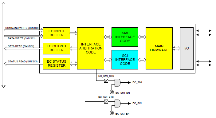
Fig. 12.1 Shared Interface
The diagram above depicts the general register model supported by the ACPI Embedded Controller Interface.
The first method uses an embedded controller interface shared between OSPM and the system management code, which requires the Global Lock semaphore overhead to arbitrate ownership. The second method is a dedicated embedded controller decode range for sole use by OSPM driver. The following diagram illustrates the embedded controller architecture that includes a dedicated ACPI interface.
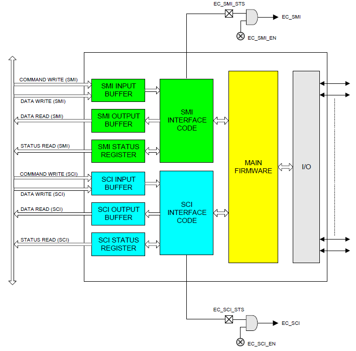
Fig. 12.2 Private Interface
The private interface allows OSPM to communicate with the embedded controller without the additional software overhead associated with using the Global Lock. Several common system configurations can provide the additional embedded controller interfaces:
Non-shared embedded controller. This will be the most common case where there is no need for the system management handler to communicate with the embedded controller when the system transitions to ACPI mode. OSPM processes all normal types of system management events, and the system management handler does not need to take any actions.
Integrated keyboard controller and embedded controller. This provides three host interfaces as described earlier by including the standard keyboard controller in an existing component (chip set, I/O controller) and adding a discrete, standard embedded controller with two interfaces for system management activities.
Standard keyboard controller and embedded controller. This provides three host interfaces by providing a keyboard controller as a distinct component, and two host interfaces are provided in the embedded controller for system management activities.
Two embedded controllers. This provides up to four host interfaces by using two embedded controllers; one controller for system management activities providing up to two host interfaces, and one controller for keyboard controller functions providing up to two host interfaces.
Embedded controller and no keyboard controller. Future platforms might provide keyboard functionality through an entirely different mechanism, which would allow for two host interfaces in an embedded controller for system management activities.
To handle the general embedded controller interface (as opposed to a dedicated interface) model, a method is available to make the embedded controller a shareable resource between multiple tasks running under the operating system’s control and the system management interrupt handler. This method, as described in this section, requires several changes:
Additional external hardware
Embedded controller firmware changes
System management interrupt handler firmware changes
Operating software changes
Access to the shared embedded controller interface requires additional software to arbitrate between the operating system’s use of the interface and the system management handler’s use of the interface. This is done using the Global Lock as described in Section 6.5.7, but is not supported on HW-reduced ACPI platforms.
This interface sharing protocol also requires embedded controller firmware changes, in order to ensure that collisions do not occur at the interface. A collision could occur if a byte is placed in the system output buffer and an interrupt is then generated. There is a small window of time when the incorrect recipient could receive the data. This problem is resolved by ensuring that the firmware in the embedded controller does not place any data in the output buffer until it is requested by OSPM or the system management handler.
More detailed algorithms and descriptions are provided in the following sections.
12.2. Embedded Controller Register Descriptions
The embedded controller contains three registers at two address locations: EC_SC and EC_DATA. The EC_SC, or Embedded Controller Status/Command register, acts as two registers: a status register for reads to this port and a command register for writes to this port. The EC_DATA (Embedded Controller Data register) acts as a port for transferring data between the host CPU and the embedded controller.
12.2.1. Embedded Controller Status, EC_SC (R)
This is a read-only register that indicates the current status of the embedded controller interface.
Bit7 |
Bit6 |
Bit5 |
Bit4 |
Bit3 |
Bit2 |
Bit1 |
Bit0 |
|---|---|---|---|---|---|---|---|
IGN |
SMI_EVT |
SCI_EVT |
BURST |
CMD |
IGN |
IBF |
OBF |
Where:
IGN |
Ignored |
|---|---|
SMI_EVT: |
1 - Indicates SMI event is pending (requesting SMI query). |
0 - No SMI events are pending. |
|
SCI_EVT: |
1 - Indicates SCI event is pending (requesting SCI query). |
0 - No SCI events are pending. |
|
BURST: |
1 - Controller is in burst mode for polled command processing. |
0 - Controller is in normal mode for interrupt-driven command processing. |
|
CMD: |
1 - Byte in data register is a command byte (only used by controller). |
0 - Byte in data register is a data byte (only used by controller). |
|
IBF: |
1 - Input buffer is full (data ready for embedded controller). |
0 - Input buffer is empty. |
|
OBF: |
1 - Output buffer is full (data ready for host). |
0 - Output buffer is empty. |
The Output Buffer Full (OBF) flag is set when the embedded controller has written a byte of data into the command or data port but the host has not yet read it. After the host reads the status byte and sees the OBF flag set, the host reads the data port to get the byte of data that the embedded controller has written. After the host reads the data byte, the OBF flag is cleared automatically by hardware. This signals the embedded controller that the data has been read by the host and the embedded controller is free to write more data to the host.
The Input Buffer Full (IBF) flag is set when the host has written a byte of data to the command or data port, but the embedded controller has not yet read it. After the embedded controller reads the status byte and sees the IBF flag set, the embedded controller reads the data port to get the byte of data that the host has written. After the embedded controller reads the data byte, the IBF flag is automatically cleared by hardware. This is the signal to the host that the data has been read by the embedded controller and that the host is free to write more data to the embedded controller.
The SCI event (SCI_EVT) flag is set when the embedded controller has detected an internal event that requires the operating system’s attention. The embedded controller sets this bit in the status register, and generates an SCI to OSPM. OSPM needs this bit to differentiate command-complete SCIs from notification SCIs. OSPM uses the query command to request the cause of the SCI_EVT and take action. For more information, see Embedded Controller Command Set.
The SMI event (SMI_EVT) flag is set when the embedded controller has detected an internal event that requires the system management interrupt handler’s attention. The embedded controller sets this bit in the status register before generating an SMI.
The Burst (BURST) flag indicates that the embedded controller has received the burst enable command from the host, has halted normal processing, and is waiting for a series of commands to be sent from the host. This allows OSPM or system management handler to quickly read and write several bytes of data at a time without the overhead of SCIs between the commands.
12.2.2. Embedded Controller Command, EC_SC (W)
This is a write-only register that allows commands to be issued to the embedded controller. Writes to this port are latched in the input data register and the input buffer full flag is set in the status register. Writes to this location also cause the command bit to be set in the status register. This allows the embedded controller to differentiate the start of a command sequence from a data byte write operation.
12.2.3. Embedded Controller Data, EC_DATA (R/W)
This is a read/write register that allows additional command bytes to be issued to the embedded controller, and allows OSPM to read data returned by the embedded controller. Writes to this port by the host are latched in the input data register, and the input buffer full flag is set in the status register. Reads from this register return data from the output data register and clear the output buffer full flag in the status register.
12.3. Embedded Controller Command Set
The embedded controller command set allows OSPM to communicate with the embedded controllers. ACPI defines the commands and their byte encodings for use with the embedded controller that are shown in the following table.
Embedded Controller Command |
Command Byte Encoding |
|---|---|
Read Embedded Controller (RD_EC) |
0x80 |
Write Embedded Controller (WR_EC) |
0x81 |
Burst Enable Embedded Controller (BE_EC) |
0x82 |
Burst Disable Embedded Controller (BD_EC) |
0x83 |
Query Embedded Controller (QR_EC) |
0x84 |
12.3.1. Read Embedded Controller, RD_EC (0x80)
This command byte allows OSPM to read a byte in the address space of the embedded controller. This command byte is reserved for exclusive use by OSPM, and it indicates to the embedded controller to generate SCIs in response to related transactions (that is, IBF=0 or OBF=1 in the EC Status Register), rather than SMIs. This command consists of a command byte written to the Embedded Controller Command register (EC_SC), followed by an address byte written to the Embedded Controller Data register (EC_DATA). The embedded controller then returns the byte at the addressed location. The data is read at the data port after the OBF flag is set.
12.3.2. Write Embedded Controller, WR_EC (0x81)
This command byte allows OSPM to write a byte in the address space of the embedded controller. This command byte is reserved for exclusive use by OSPM, and it indicates to the embedded controller to generate SCIs in response to related transactions (that is, IBF=0 or OBF=1 in the EC Status Register), rather than SMIs. This command allows OSPM to write a byte in the address space of the embedded controller. It consists of a command byte written to the Embedded Controller Command register (EC_SC), followed by an address byte written to the Embedded Controller Data register (EC_DATA), followed by a data byte written to the Embedded Controller Data Register (EC_DATA); this is the data byte written at the addressed location.
12.3.3. Burst Enable Embedded Controller, BE_EC (0x82)
This command byte allows OSPM to request dedicated attention from the embedded controller and (except for critical events) prevents the embedded controller from doing tasks other than receiving command and data from the host processor (either the system management interrupt handler or OSPM). This command is an optimization that allows the host processor to issue several commands back to back, in order to reduce latency at the embedded controller interface. When the controller is in the burst mode, it should transition to the burst disable state if the host does not issue a command within the following guidelines:
First Access - 400 microseconds
Subsequent Accesses - 50 microseconds each
Total Burst Time - 1 millisecond
In addition, the embedded controller can disengage the burst mode at any time to process a critical event. If the embedded controller disables burst mode for any reason other than the burst disable command, it should generate an SCI to OSPM to indicate the change.
While in burst mode, the embedded controller follows these guidelines for OSPM driver:
SCIs are generated as normal, including IBF=0 and OBF=1.
Accesses should be responded to within 50 microseconds.
Burst mode is entered in the following manner:
OSPM driver writes the Burst Enable Embedded Controller, BE_EC (0x82) command byte and then the Embedded Controller will prepare to enter the Burst mode. This includes processing any routine activities such that it should be able to remain dedicated to OSPM interface for ~ 1 microsecond.
The Embedded Controller sets the Burst bit of the Embedded Controller Status Register, puts the Burst Acknowledge byte (0x90) into the SCI output buffer, sets the OBF bit, and generates an SCI to signal OSPM that it is in Burst mode.
Burst mode is exited the following manner:
OSPM driver writes the Burst Disable Embedded Controller, BD_EC (0x83) command byte and then the Embedded Controller will exit Burst mode by clearing the Burst bit in the Embedded Controller Status register and generating an SCI signal (due to IBF=0).
The Embedded Controller clears the Burst bit of the Embedded Controller Status Register.
12.3.4. Burst Disable Embedded Controller, BD_EC (0x83)
This command byte releases the embedded controller from a previous burst enable command and allows it to resume normal processing. This command is sent by OSPM or system management interrupt handler after it has completed its entire queued command sequence to the embedded controller.
12.3.5. Query Embedded Controller, QR_EC (0x84)
OSPM driver sends this command when the SCI_EVT flag in the EC_SC register is set. When the embedded controller has detected a system event that must be communicated to OSPM, it first sets the SCI_EVT flag in the EC_SC register, generates an SCI, and then waits for OSPM to send the query (QR_EC) command. OSPM detects the embedded controller SCI, sees the SCI_EVT flag set, and sends the query command to the embedded controller. Upon receipt of the QR_EC command byte, the embedded controller places a notification byte with a value between 0-255, indicating the cause of the notification. The notification byte indicates which interrupt handler operation should be executed by OSPM to process the embedded controller SCI. The query value of zero is reserved for a spurious query result and indicates “no outstanding event.”
12.4. SMBus Host Controller Notification Header (Optional), OS_SMB_EVT
This query command notification header is the special return code that indicates events with an SMBus controller implemented within an embedded controller. These events include:
Command completion
Command error
Alarm reception
The actual notification value is declared in the EC-SMB-HC device object in the ACPI Namespace.
12.5. Embedded Controller Firmware
The embedded controller firmware must obey the following rules in order to be ACPI-compatible:
SMI Processing. Although it is not explicitly stated in the command specification section, a shared embedded controller interface has a separate command set for communicating with each environment it plans to support. In other words, the embedded controller knows which environment is generating the command request, as well as which environment is to be notified upon event detection, and can then generate the correct interrupts and notification values. This implies that a system management handler uses commands that parallel the functionality of all the commands for ACPI including query, read, write, and any other implemented specific commands.
SCI/SMI Task Queuing. If the system design is sharing the interface between both a system management interrupt handler and OSPM, the embedded controller should always be prepared to queue a notification if it receives a command. The embedded controller only sets the appropriate event flag in the status (EC_SC) register if the controller has detected an event that should be communicated to the OS or system management handler. The embedded controller must be able to field commands from either environment without loss of the notification event. At some later time, the OS or system management handler issues a query command to the embedded controller to request the cause of the notification event.
Notification Management. The use of the embedded controller means using the query (QR_EC) command to notify OSPM of system events requiring action. If the embedded controller is shared with the operating system, the SMI handler uses the SMI_EVT flag and an SMI query command (not defined in this document) to receive the event notifications. The embedded controller doesn’t place event notifications into the output buffer of a shared interface unless it receives a query command from OSPM or the system management interrupt handler.
12.6. Interrupt Model
The EC Interrupt Model uses pulsed interrupts to speed the clearing process. The Interrupt is firmware generated using an EC general-purpose output and has the waveform shown in Interrupt Model . The embedded controller SCI is always wired directly to a GPE input or a GPIO pin, and OSPM driver treats this as an edge event (the EC SCI cannot be shared).
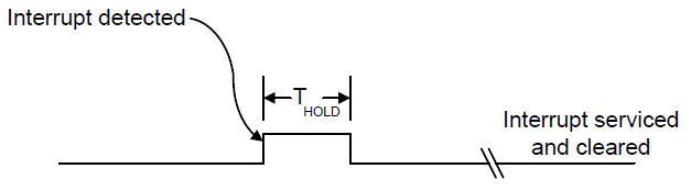
Fig. 12.3 Interrupt Model
12.6.1. Event Interrupt Model
The embedded controller must generate SCIs for the events listed in the following table.
Event |
Description |
|---|---|
IBF=0 |
Signals that the embedded controller has read the last command or data from the input buffer and the host is free to send more data. |
OBF=1 |
Signals that the embedded controller has written a byte of data into the output buffer and the host is free to read the returned data. |
SCI_EVT=1 |
Signals that the embedded controller has detected an event that requires OS attention. OSPM should issue a query (QR_EC) command to find the cause of the event. |
12.6.2. Command Interrupt Model
The embedded controller must generate SCIs for commands as follows:
Byte #1 |
(Command byte Header) |
Interrupt on IBF=0 |
Byte #2 |
(Address byte to read) |
No Interrupt |
Byte #3 |
(Data read to host) |
Interrupt on OBF=1 |
Byte #1 |
(Command byte Header) |
Interrupt on IBF=0 |
Byte #2 |
(Address byte to write) |
Interrupt on IBF=0 |
Byte #3 |
(Data to read ) |
Interrupt on IBF=0 |
Byte #1 |
(Command byte Header) |
No Interrupt |
Byte #2 |
(Query value to host) |
Interrupt on OBF=1 |
Byte #1 |
(Command byte Header) |
No Interrupt |
Byte #2 |
(Burst acknowledge byte) |
Interrupt on OBF=1 |
Byte #1 |
(Command byte Header) |
Interrupt on IBF=0 |
12.7. Embedded Controller Interfacing Algorithms
To initiate communications with the embedded controller, OSPM or system management handler acquires ownership of the interface. This ownership is acquired through the use of the Global Lock, or is owned by default by OSPM as a non-shared resource (and the Global Lock is not required for accessibility).
After ownership is acquired, the protocol always consists of the passing of a command byte. The command byte will indicate the type of action to be taken. Following the command byte, zero or more data bytes can be exchanged in either direction. The data bytes are defined according to the command byte that is transferred.
The embedded controller also has two status bits that indicate whether the registers have been read. This is used to ensure that the host or embedded controller has received data from the embedded controller or host. When the host writes data to the command or data register of the embedded controller, the input buffer flag (IBF) in the status register is set within 1 microsecond. When the embedded controller reads this data from the input buffer, the input buffer flag is reset. When the embedded controller writes data into the output buffer, the output buffer flag (OBF) in the status register is set. When the host processor reads this data from the output buffer, the output buffer flag is reset.
12.8. Embedded Controller Description Information
Certain aspects of the embedded controller’s operation have OEM-definable values associated with them. The following is a list of values that are defined in the software layers of the ACPI specification:
Status flag indicating whether the interface requires the use of the Global Lock.
Bit position of embedded controller interrupt in general-purpose status register.
Decode address for command/status register.
Decode address for data register.
Base address and query value of any EC-SMBus controller.
For implementation details of the above information, see Defining an Embedded Controller Device in ACPI Namespace and Defining an EC SMBus Host Controller in ACPI Namespace.
An embedded controller will require the inclusion of the GLK method in its ACPI namespace if potentially contentious accesses to device resources are performed by non-OS code. See _GLK (Global Lock) for details about the _GLK method.
12.9. SMBus Host Controller Interface via Embedded Controller
This section specifies a standard interface that an ACPI-compatible OS can use to communicate with embedded controller-based SMBus host controllers (EC-SMB-HC). This interface allows the host processor (under control of OSPM) to manage devices on the SMBus. Typical devices residing on the SMBus include Smart Batteries, Smart Battery Chargers, contrast/backlight control, and temperature sensors.
The EC-SMB-HC interface consists of a block of registers that reside in embedded controller space. These registers are used by software to initiate SMBus transactions and receive SMBus notifications. By using a well-defined register set, OS software can be written to operate with any vendor’s embedded controller hardware.
Certain SMBus segments have special requirements that the host controller filters certain SMBus commands (for example, to prevent an errant application or virus from potentially damaging the battery subsystem). This is most easily accomplished by implementing the host interface controller through an embedded controller–as embedded controller can easily filter out potentially problematic commands.
Notice that an EC-SMB-HC interface will require the inclusion of the GLK method in its ACPI namespace if potentially contentious accesses to device resources are performed by non-OS code. See _GLK (Global Lock) for details on using the _GLK method.
12.9.1. Register Description
The EC-SMBus host interface is a flat array of registers that are arranged sequentially in the embedded controller address space.
12.9.1.1. Status Register, SMB_STS
This register indicates general status on the SMBus. This includes SMB-HC command completion status, alarm received status, and error detection status (the error codes are defined later in this section). This register is cleared to zeroes (except for the ALRM bit) whenever a new command is issued using a write to the protocol (SMB_PRTCL) register. This register is always written with the error code before clearing the protocol register. The SMB-HC query event (that is, an SMB-HC interrupt) is raised after the clearing of the protocol register.
Note
OSPM must ensure the ALRM bit is cleared after it has been serviced by writing ‘00’ to the SMB_STS register.
Bit7 |
Bit6 |
Bit5 |
Bit4 |
Bit3 |
Bit2 |
Bit1 |
Bit0 |
Done |
ALRM |
RES |
STATUS |
Where:
DONE: |
Indicates the last command has completed and no error. |
ALRM: |
Indicates an SMBus alarm message has been received. |
RES: |
Reserved |
STATUS: |
Indicates SMBus communication status for one of the reasons listed in the following table. |
Status Code |
Name |
Description |
|---|---|---|
00h |
SMBus OK |
Indicates the transaction has been successfully completed. |
07h |
SMBus Unknown Failure |
Indicates failure because of an unknown SMBus error. |
10h |
SMBus Device Address Not Acknowledged |
Indicates the transaction failed because the slave device address was not acknowledged. |
11h |
SMBus Device Error Detected |
Indicates the transaction failed because the slave device signaled an error condition. |
12h |
SMBus Device Command Access Denied |
Indicates the transaction failed because the SMBus host does not allow the specific command for the device being addressed. For example, the SMBus host might not allow a caller to adjust the Smart Battery Charger’s output. |
13h |
SMBus Unknown Error |
Indicates the transaction failed because the SMBus host encountered an unknown error. |
17h |
SMBus Device Access Denied |
Indicates the transaction failed because the SMBus host does not allow access to the device addressed. For example, the SMBus host might not allow a caller to directly communicate with an SMBus device that controls the system’s power planes. |
18h |
SMBus Timeout |
Indicates the transaction failed because the SMBus host detected a timeout on the bus. |
19h |
SMBus Host Unsupported Protocol |
Indicates the transaction failed because the SMBus host does not support the requested protocol. |
1Ah |
SMBus Busy |
Indicates that the transaction failed because the SMBus host reports that the SMBus is presently busy with some other transaction. For example, the Smart Battery might be sending charging information to the Smart Battery Charger. |
1Fh |
SMBus PEC (CRC-8) Error |
Indicates that a Packet Error Checking (PEC) error occurred during the last transaction. |
All other error codes are reserved.
12.9.1.2. Protocol Register, SMB_PRTCL
This register determines the type of SMBus transaction generated on the SMBus. In addition to indicating the protocol type to the SMB-HC, a write to this register initiates the transaction on the SMBus. Notice that bit 7 of the protocol value is used to indicate whether packet error checking should be employed. A value of 1 (one) in this bit indicates that PEC format should be used for the specified protocol, and a value of 0 (zero) indicates the standard (non-PEC) format should be used.
Bit7 |
Bit6 to Bit0 |
|---|---|
PEC |
PROTOCOL |
Where the PROTOCOL values are as follows:
0x00 |
Controller Not In Use |
0x01 |
Reserved |
0x02 |
Write Quick Command |
0x03 |
Read Quick Command |
0x04 |
Send Byte |
0x05 |
Receive Byte |
0x06 |
Write Byte |
0x07 |
Read Byte |
0x08 |
Write Word |
0x09 |
Read Word |
0x0A |
Write Block |
0x0B |
Read Block |
0x0C |
Process Call |
0x0D |
Block Write-Block Read Process Call |
For example, the protocol value of 0x09 would be used to communicate to a device that supported the standard read word protocol. If this device also supported packet error checking for this protocol, a value of 0x89 (read word with PEC) could optionally be used. See the SMBus specification for more information on packet error checking.
When OSPM initiates a new command such as write to the SMB_PRTCL register, the SMBus controller first updates the SMB_STS register and then clears the SMB_PRTCL register. After the SMB_PRTCL register is cleared, the host controller query value is raised.
All other protocol values are reserved.
12.9.1.3. Address Register, SMB_ADDR
This register contains the 7-bit address to be generated on the SMBus. This is the first byte to be sent on the SMBus for all of the different protocols.
Bit7 to Bit1 |
Bit0 |
|---|---|
ADDRESS (A6:A0) |
RES |
Where:
RES: |
Reserved |
ADDRESS: |
7-bit SMBus address. This address is not zero-aligned (in other words, it is only a 7-bit address (A6:A0) that is aligned from bit 1-7). |
12.9.1.4. Command Register, SMB_CMD
This register contains the command byte that will be sent to the target device on the SMBus and is used for the following protocols: send byte, write byte, write word, read byte, read word, process call, block read and block write. It is not used for the quick commands or the receive byte protocol, and as such, its value is a “don’t care” for those commands.
Bit7 to Bit0 |
COMMAND |
Where:
COMMAND |
Command byte to be sent to SMBus device. |
12.9.1.5. Data Register Array, SMB_DATA[i], i=0-31
This bank of registers contains the remaining bytes to be sent or received in any of the different protocols that can be run on the SMBus. The SMB_DATA[i] registers are defined on a per-protocol basis and, as such, provide efficient use of register space.
Bit7 to Bit0 |
DATA |
Where:
DATA |
One byte of data to be sent or received (depending upon protocol). |
12.9.1.6. Block Count Register, SMB_BCNT
This register contains the number of bytes of data present in the SMB_DATA[i] registers preceding any write block and following any read block transaction. The data size is defined on a per protocol basis.
Bit7 to Bit5 |
Bit4 to Bit0 |
|---|---|
RES |
BCNT |
12.9.1.7. Alarm Address Register, SMB_ALRM_ADDR
This register contains the address of an alarm message received by the host controller, at slave address 0x8, from the SMBus master that initiated the alarm. The address indicates the slave address of the device on the SMBus that initiated the alarm message. The status of the alarm message is contained in the SMB_ALRM_DATAx registers. Once an alarm message has been received, the SMB-HC will not receive additional alarm messages until the ALRM status bit is cleared.
Bit7 to Bit1 |
Bit0 |
|---|---|
ADDRESS (A6:A0) |
RES |
Where:
RES: |
Reserved |
ADDRESS: |
Slave address (A6:A0) of the SMBus device that initiated the SMBus alarm message. |
12.9.1.8. Alarm Data Registers, SMB_ALRM_DATA[0], SMB_ALRM_DATA[1]
These registers contain the two data bytes of an alarm message received by the host controller, at slave address 0x8, from the SMBus master that initiated the alarm. These data bytes indicate the specific reason for the alarm message, such that OSPM can take actions. Once an alarm message has been received, the SMB-HC will not receive additional alarm messages until the ALRM status bit is cleared.
Bit7 to Bit0 |
DATA (D7:D0) |
Where:
DATA |
Data byte received in alarm message. |
The alarm address and alarm data registers are not read by OSPM until the alarm status bit is set. OSPM driver then reads the 3 bytes, and clears the alarm status bit to indicate that the alarm registers are now available for the next event.
12.9.2. Protocol Description
This section describes how to initiate the different protocols on the SMBus through the interface described in Register Description. The registers should all be written with the appropriate values before writing the protocol value that starts the SMBus transaction. All transactions can be completed in one pass.
12.9.2.1. Write Quick
Data Sent:
SMB_ADDR: |
Address of SMBus device. |
SMB_PRTCL: |
Write 0x02 to initiate the write quick protocol. |
Data Returned:
SMB_STS: |
Status code for transaction. |
SMB_PRTCL: |
0x00 to indicate command completion. |
12.9.2.2. Read Quick
Data Sent:
SMB_ADDR: |
Address of SMBus device. |
SMB_PRTCL: |
Write 0x03 to initiate the read quick protocol. |
Data Returned:
SMB_STS: |
Status code for transaction. |
SMB_PRTCL: |
0x00 to indicate command completion. |
12.9.2.3. Send Byte
Data Sent:
SMB_ADDR: |
Address of SMBus device. |
SMB_CMD: |
Command byte to be sent. |
SMB_PRTCL: |
Write 0x04 to initiate the send byte protocol, or 0x84 to initiate the send byte protocol with PEC. |
Data Returned:
SMB_STS: |
Status code for transaction. |
SMB_PRTCL: |
0x00 to indicate command completion. |
12.9.2.4. Receive Byte
Data Sent:
SMB_ADDR: |
Address of SMBus device. |
SMB_PRTCL: |
Write 0x05 to initiate the receive byte protocol, or 0x85 to initiate the receive byte protocol with PEC. |
Data Returned:
SMB_DATA[0]: |
Data byte received. |
SMB_STS: |
Status code for transaction. |
SMB_PRTCL: |
0x00 to indicate command completion. |
12.9.2.5. Write Byte
Data Sent:
SMB_ADDR: |
Address of SMBus device. |
SMB_CMD: |
Command byte to be sent. |
SMB_DATA[0]: |
Data byte to be sent. |
SMB_PRTCL: |
Write 0x06 to initiate the write byte protocol, or 0x86 to initiate the write byte protocol with PEC. |
Data Returned:
SMB_STS: |
Status code for transaction. |
SMB_PRTCL: |
0x00 to indicate command completion. |
12.9.2.6. Read Byte
Data Sent:
SMB_ADDR: |
Address of SMBus device. |
SMB_CMD: |
Command byte to be sent. |
SMB_PRTCL: |
Write 0x07 to initiate the read byte protocol, or 0x87 to initiate the read byte protocol with PEC. |
Data Returned:
SMB_DATA[0]: |
Data byte received. |
SMB_STS: |
Status code for transaction. |
SMB_PRTCL: |
0x00 to indicate command completion. |
12.9.2.7. Write Word
Data Sent:
SMB_ADDR: |
Address of SMBus device. |
SMB_CMD: |
Command byte to be sent. |
SMB_DATA[0]: |
Low data byte to be sent. |
SMB_DATA[1]: |
High data byte to be sent. |
SMB_PRTCL: |
Write 0x08 to initiate the write word protocol, or 0x88 to initiate the write word protocol with PEC. |
Data Returned:
SMB_STS: |
Status code for transaction. |
SMB_PRTCL: |
0x00 to indicate command completion. |
12.9.2.8. Read Word
Data Sent:
SMB_ADDR: |
Address of SMBus device. |
SMB_CMD: |
Command byte to be sent. |
SMB_PRTCL: |
Write 0x09 to initiate the read word protocol, or 0x89 to initiate the read word protocol with PEC. |
Data Returned:
SMB_DATA[0]: |
Low data byte received. |
SMB_DATA[1]: |
High data byte received. |
SMB_STS: |
Status code for transaction. |
SMB_PRTCL: |
0x00 to indicate command completion. |
12.9.2.9. Write Block
Data Sent:
SMB_ADDR: |
Address of SMBus device. |
SMB_CMD: |
Command byte to be sent. |
SMB_DATA[0-31]: |
Data bytes to write (1-32). |
SMB_BCNT: |
Number of data bytes (1-32) to be sent. |
SMB_PRTCL: |
Write 0x0A to initiate the write block protocol, or 0x8A to initiate the write block protocol with PEC. |
Data Returned:
SMB_PRTCL: |
0x00 to indicate command completion. |
SMB_STS: |
Status code for transaction. |
12.9.2.10. Read Block
Data Sent:
SMB_ADDR: |
Address of SMBus device. |
SMB_CMD: |
Command byte to be sent. |
SMB_PRTCL: |
Write 0x0B to initiate the read block protocol, or 0x8B to initiate the read block protocol with PEC. |
Data Returned:
SMB_BCNT: |
Number of data bytes (1-32) received. |
SMB_DATA[0-31]: |
Data bytes received (1-32). |
SMB_STS: |
Status code for transaction. |
SMB_PRTCL: |
0x00 to indicate command completion. |
12.9.2.11. Process Call
Data Sent:
SMB_ADDR: |
Address of SMBus device. |
SMB_CMD: |
Command byte to be sent. |
SMB_DATA[0]: |
Low data byte to be sent. |
SMB_DATA[1]: |
High data byte to be sent. |
SMB_PRTCL: |
Write 0x0C to initiate the process call protocol, or 0x8C to initiate the process call protocol with PEC. |
Data Returned:
SMB_DATA[0]: |
Low data byte received. |
SMB_DATA[1]: |
High data byte received. |
SMB_STS: |
Status code for transaction. |
SMB_PRTCL: |
0x00 to indicate command completion. |
12.9.2.12. Block Write-Block Read Process Call
Data Sent:
SMB_ADDR: |
Address of SMBus device. |
SMB_CMD: |
Command byte to be sent. |
SMB_DATA[0-31]: |
Data bytes to write (1-31). |
SMB_BCNT: |
Number of data bytes (1-31) to be sent. |
SMB_PRTCL: |
Write 0x0D to initiate the write block-read block process call protocol, or 0x8D to initiate the write block-read block process call protocol with PEC. |
Data Returned:
SMB_BCNT: |
Number of data bytes (1-31) received. |
SMB_DATA[0-31]: |
Data bytes received (1-31). |
SMB_STS: |
Status code for transaction. |
SMB_PRTCL: |
0x00 to indicate command completion. |
Note
The following restrictions apply above: The aggregate data length of the write and read blocks must not exceed 32 bytes and each block (write and read) must contain at least 1 byte of data.
12.9.2.13. SMBus Register Set
The register set for the SMB-HC has the following format. All registers are 8 bit.
Location |
Register Name |
Description |
|---|---|---|
BASE+0 |
SMB_PRTCL |
Protocol register |
BASE+1 |
SMB_STS |
Status register |
BASE+2 |
SMB_ADDR |
Address register |
BASE+3 |
SMB_CMD |
Command register |
BASE+4 |
SMB_DATA[0] |
Data register zero |
BASE+5 |
SMB_DATA[1] |
Data register one |
BASE+6 |
SMB_DATA[2] |
Data register two |
BASE+7 |
SMB_DATA[3] |
Data register three |
BASE+8 |
SMB_DATA[4] |
Data register four |
BASE+9 |
SMB_DATA[5] |
Data register five |
BASE+10 |
SMB_DATA[6] |
Data register six |
BASE+11 |
SMB_DATA[7] |
Data register seven |
BASE+12 |
SMB_DATA[8] |
Data register eight |
BASE+13 |
SMB_DATA[9] |
Data register nine |
BASE+14 |
SMB_DATA[10] |
Data register ten |
BASE+15 |
SMB_DATA[11] |
Data register eleven |
BASE+16 |
SMB_DATA[12] |
Data register twelve |
BASE+17 |
SMB_DATA[13] |
Data register thirteen |
BASE+18 |
SMB_DATA[14] |
Data register fourteen |
BASE+19 |
SMB_DATA[15] |
Data register fifteen |
BASE+20 |
SMB_DATA[16] |
Data register sixteen |
BASE+21 |
SMB_DATA[17] |
Data register seventeen |
BASE+22 |
SMB_DATA[18] |
Data register eighteen |
BASE+23 |
SMB_DATA[19] |
Data register nineteen |
BASE+24 |
SMB_DATA[20] |
Data register twenty |
BASE+25 |
SMB_DATA[21] |
Data register twenty-one |
BASE+26 |
SMB_DATA[22] |
Data register twenty-two |
BASE+27 |
SMB_DATA[23] |
Data register twenty-three |
BASE+28 |
SMB_DATA[24] |
Data register twenty-four |
BASE+29 |
SMB_DATA[25] |
Data register twenty-five |
BASE+30 |
SMB_DATA[26] |
Data register twenty-six |
BASE+31 |
SMB_DATA[27] |
Data register twenty-seven |
BASE+32 |
SMB_DATA[28] |
Data register twenty-eight |
BASE+33 |
SMB_DATA[29] |
Data register twenty-nine |
BASE+34 |
SMB_DATA[30] |
Data register thirty |
BASE+35 |
SMB_DATA[31] |
Data register thirty-one |
BASE+36 |
SMB_BCNT |
Block Count Register |
BASE+37 |
SMB_ALRM_ADDR |
Alarm address |
BASE+38 |
SMB_ALRM_DATA[0] |
Alarm data register zero |
BASE+39 |
SMB_ALRM_DATA[1] |
Alarm data register one |
12.10. SMBus Devices
The embedded controller interface provides the system with a standard method to access devices on the SMBus. It does not define the data and/or access protocol(s) used by any particular SMBus device. Further, the embedded controller can (and probably will) serve as a gatekeeper to prevent accidental or malicious access to devices on the SMBus.
Some SMBus devices are defined by their address and a specification that describes the data and the protocol used to access that data. For example, the Smart Battery System devices are defined by a series of specifications including:
Smart Battery Data specification
Smart Battery Charger specification
Smart Battery Selector specification
Smart Battery System Manager specification
The embedded controller can also be used to emulate (in part or totally) any SMBus device.
12.10.1. SMBus Device Access Restrictions
In some cases, the embedded controller interface will not allow access to a particular SMBus device. Some SMBus devices can and do communicate directly between themselves. Unexpected accesses can interfere with their normal operation and cause unpredictable results.
12.10.2. SMBus Device Command Access Restriction
There are cases where part of an SMBus device’s commands are public while others are private. Extraneous attempts to access these commands might cause interference with the SMBus device’s normal operation.
The Smart Battery and the Smart Battery Charger are good examples of devices that should not have their entire command set exposed. The Smart Battery commands the Smart Battery Charger to supply a specific charging voltage and charging current. Attempts by anyone to alter these values can cause damage to the battery or the mobile system. To protect the system’s integrity, the embedded controller interface can restrict access to these commands by returning one of the following error codes: Device Command Access Denied (0x12) or Device Access Denied (0x17).
12.11. Defining an Embedded Controller Device in ACPI Namespace
An embedded controller device is created using the named device object. The embedded controller’s device object requires the following elements:
Object |
Description |
|---|---|
_CRS |
Named object that returns the Embedded Controller’s current resource settings. Embedded Controllers are considered static resources; hence only return their defined resources. The embedded controller resides only in system I/O or memory space. The first address region returned is the data port, and the second address region returned is the status/command port for the embedded controller. If the EC is used on a HW-Reduced ACPI platform, a third resource is required, which is the GPIO Interrupt Connection resource for the EC’s SCI Interrupt. CRS is a standard device configuration control method defined in _CRS (Current Resource Settings). |
_HID |
Named object that provides the Embedded Controller’s Plug and Play identifier. This value is set to PNP0C09. _HID is a standard device configuration control method defined in _HID (Hardware ID). |
_GPE |
Named Object that evaluates to either an integer or a package. If _GPE evaluates to an integer, the value is the bit assignment of the SCI interrupt within the GPEx_STS register of a GPE block described in the FADT that the embedded controller will trigger. If _GPE evaluates to a package, then that package contains two elements. The first is an object reference to the GPE Block device that contains the GPE register that will be triggered by the embedded controller. The second element is numeric (integer) that specifies the bit assignment of the SCI interrupt within the GPEx_STS register of the GPE Block device referenced by the first element in the package. This control method is specific to the embedded controller. This method is not required on Hardware-reduced ACPI platforms. |
12.11.1. Example: EC Definition ASL Code
Example ASL code that defines an embedded controller device is shown below:
Device(EC0) {
                                        // PnP ID
    Name(_HID, EISAID("PNP0C09"))
                                        // Returns the "Current Resources" of EC
    Name(_CRS,
        ResourceTemplate(){ // port 0x62 and 0x66
            IO(Decode16, 0x62, 0x62, 0, 1),
            IO(Decode16, 0x66, 0x66, 0, 1)
        /* For HW-Reduced ACPI Platforms, include a GPIO Interrupt Connection resource,
            e.g. GPIO controller #2, pin 43.
            GpioInt(Edge, ActiveHigh, ExclusiveAndWake,PullUp 0, "\\_SB.GPI2"){43}
        */
            }
        )
                                        // Define that the EC SCI is bit 0 of the GP_STS register
        Name(_GPE, 0)                   // Not required for HW-Reduced ACPI platforms
        OperationRegion(ECOR, EmbeddedControl, 0, 0xFF)
        Field(ECOR, ByteAcc, Lock, Preserve) {
                                        // Field definitions go here
            }
        }
12.12. Defining an EC SMBus Host Controller in ACPI Namespace
An EC-SMB-HC device is defined using the named device object. The EC-SMB- HC’s device object requires the following elements:
Object |
Description |
|---|---|
_HID |
Named object that provides the EC-SMB- HC’s Plug and Play identifier. This value is be set to ACPI0001. _HID is a standard device configuration control method defined in _HID (Hardware ID). |
_EC |
Named object that evaluates to a WORD that defines the SMBus attributes needed by the SMBus driver. _EC is the Embedded Controller Offset Query Control Method. The most significant byte is the address offset in embedded controller space of the SMBus controller; the least significant byte is the query value for all SMBus events. |
12.12.1. Example: EC SMBus Host Controller ASL-Code
Example ASL code that defines an SMB-HC from within an embedded controller device is shown below:
Device(EC0)
{
    Name(_HID, EISAID("PNP0C09"))
    Name(_CRS, ResourceTemplate()
    {
        IO(Decode16, 0x62, 0x62, 0, 1), // Status port
        IO(Decode16, 0x66, 0x66, 0, 1) // command port
    })
    Name(_GPE, 0)

    Device (SMB0)
    {
        Name(_HID, "ACPI0001") // EC-SMB-HC
        Name(_UID, 0) // Unique device identifier
        Name(_EC, 0x2030) // EC offset 0x20, query bit 0x30
            :
    }
    Device (SMB1)
    {
        Name(_HID, "ACPI0001") // EC-SMB-HC
        Name(_UID, 1) // Unique device identifier
        Name(_EC, 0x8031) // EC offset 0x80, query bit 0x31
            :
    }
} // end of EC0.