9. ACPI-Defined Devices and Device-Specific Objects
This chapter describes ACPI defined devices and device-specific objects, plus the system status indicator objects declared under the \_SI scope in the ACPI Namespace.
9.1. Device Object Name Collision
Devices containing both _HID and _CID may have device specific control methods pertaining to both the device ID in the _HID and the device ID in the _CID. These device specific control methods are defined by the device owner (a standard body or a vendor or a group of vendor partners). Since these object names are not controlled by a central authority, there is a likelihood that the names of objects will conflict between two defining parties. The _DSM object described in the next section solves this conflict.
9.1.1. _DSM (Device Specific Method)
This optional object is a control method that enables devices to provide device specific control functions that are consumed by the device driver.
Arguments: (4)
Arg0 - A Buffer containing a UUID
Arg1 - An Integer containing the Revision ID
Arg2 - An Integer containing the Function Index
Arg3 - A Package that contains function-specific arguments
Return Value:
If Function Index = 0, a Buffer containing a function index bitfield. Otherwise, the return value and type depends on the UUID and revision ID (see below).
Argument Information:
Arg0: UUID - A Buffer containing the 16-byte UUID (see Universally Unique Identifiers (UUIDs))
Arg1: Revision ID - the function’s revision. This revision is specific to the UUID.
Arg2: Function Index - Represents a specific function whose meaning is specific to the UUID and Revision ID. Function indices should start with 1. Function number zero is a query function (see the special return code defined below).
Arg3: Function Arguments - a package containing the parameters for the function specified by the UUID, Revision ID and Function Index.
Successive revisions of Function Arguments must be backward compatible with earlier revisions. New UUIDs may also be created by OEMs and IHVs for custom devices and other interface or device governing bodies (e.g. the PCI SIG), as long as the UUID is different from other published UUIDs. Only the issuer of a UUID can authorize a new Function Index, Revision ID or Function Argument for that UUID.
Return Value Information:
If Function Index is zero, the return is a buffer containing one bit for each function index, starting with zero. Bit 0 indicates whether there is support for any functions other than function 0 for the specified UUID and Revision ID. If set to zero, no functions are supported (other than function zero) for the specified UUID and Revision ID. If set to one, at least one additional function is supported. For all other bits in the buffer, a bit is set to zero to indicate if that function index is not supported for the specific UUID and Revision ID. (For example, bit 1 set to 0 indicates that function index 1 is not supported for the specific UUID and Revision ID.)
If the bit representing a particular function index would lie outside of the buffer, it should be assumed to be 0 (that is, not supported).
If Function Index is non-zero, the return is any data object. The type and meaning of the returned data object depends on the UUID, Revision ID, Function Index, and Function Arguments.
Note
For backward compatibility _DSM requires that each Revision ID support all of the functions defined by all previous Revision IDs for the same UUID.*
Implementation Note
Since the purpose of the _DSM method is to avoid the namespace collision, the implementation of this method shall not use any other method or data object which is not defined in this specification unless its driver and usage is completely under the control of the platform vendor.
Example:
// _DSM - Device Specific Method
//
// Arg0: UUID Unique function identifier
// Arg1: Integer Revision Level
// Arg2: Integer Function Index (0 = Return Supported Functions)
// Arg3: Package Parameters
Function(_DSM,{IntObj,BuffObj},{BuffObj, IntObj, IntObj, PkgObj})
{
   //
   // Switch based on which unique function identifier was passed in
   //
 switch(Arg0)
 {
   //
   // First function identifier
   //
  case(ToUUID("893f00a6-660c-494e-bcfd-3043f4fb67c0"))
  {
   switch(Arg2)
   {
    //
    // Function 0: Return supported functions, based on revision
    //
    case(0)
    {
    switch(Arg1)
    {
     // revision 0: functions 1-4 are supported
     case(0) {return (Buffer() {0x1F})}
     // revision 1: functions 1-5 are supported
     case(1) {return (Buffer() {0x3F})}
    }
    // revision 2+: functions 1-7 are supported
    return (Buffer() {0xFF})
   }
   //
   // Function 1:
   //
   case(1)
   {
    ... function 1 code ...
    Return(Zero)
   }
   //
   // Function 2:
   //
   case(2)
   {
    ... function 2 code ...
    Return(Buffer(){0x00})
   }
   case(3) { ... function 3 code ...}
   case(4) { ... function 4 code ...}
   case(5) { if (LLess(Arg1,1) BreakPoint; ... function 5 code ... }
   case(6) { if (LLess(Arg1,2) BreakPoint; ... function 6 code ... )
   case(7) { if (LLess(Arg1,3) BreakPoint; ... function 7 code ... )
   default {BreakPoint }
  }
 }
 //
 // Second function identifier
 //
 case(ToUUID("107ededd-d381-4fd7-8da9-08e9a6c79644"))
 {
  //
  // Function 0: Return supported functions (there is only one revision)
  //
  if (LEqual(Arg2,Zero))
    return (Buffer() {0x3}) // only one function supported
  //
  // Function 1
  //
  if (LEqual(Arg2,One))
  {
   ... function 1 code ...
   Return(Unicode("text"))
   }
   //
   // Function 2+: Runtime Error
   //
    else
     BreakPoint;
   }
  }
  //
  // If not one of the UUIDs we recognize, then return a buffer
  // with bit 0 set to 0 indicating no functions supported.
  //
  return(Buffer(){0})
 }
9.2. \_SI System Indicators
ACPI provides an interface for a variety of simple and icon-style indicators on a system. All indicator controls are in the \_SI portion of the namespace. The following table lists all defined system indicators. (Notice that there are also per-device indicators specified for battery devices).
Object |
Description |
|---|---|
_SST |
System status indicator |
_MSG |
Messages waiting indicator |
_BLT |
Battery Level Threshold |
9.2.1. _SST (System Status)
This optional object is a control method that OSPM invokes to set the system status indicator as desired.
Arguments:(1)
Arg0 - An Integer containing the system status indicator identifier:
0 - No system state indication. Indicator off
1 - Working
2 - Waking
3 - Sleeping. Used to indicate system state S1, S2, or S3
4 - Sleeping with context saved to non-volatile storage
Return Value:
None
9.2.2. _MSG (Message)
This control method sets the system’s message-waiting status indicator.
Arguments:(1)
Arg0 - An Integer containing the number of waiting messages
Return Value:
None
9.2.3. _BLT (Battery Level Threshold)
This optional control method is used by OSPM to indicate to the platform the user’s preference for various battery level thresholds. This method allows platform battery indicators to be synchronized with OSPM provided battery notification levels. Note that if _BLT is implemented on a multi-battery system, it is required that the power unit for all batteries must be the same (see Section 10.2 for more details on battery levels.
Arguments:(3)
Arg0 - An Integer containing the preferred threshold for the battery warning level
Arg1 - An Integer containing the preferred threshold for the battery low level
Arg2 - An Integer containing the preferred threshold for the battery wake level
Return Value:
None
Additional Information
The battery warning level in the range 0x00000001 - 0x7FFFFFFF (in units of mWh or mAh, depending on the Power Units value) is the user’s preference for battery warning. If the level specified is less than the design capacity of warning, it may be ignored by the platform so that the platform can ensure a successful wake on low battery.
The battery low level in the range 0x00000001 - 0x7FFFFFFF (in units of mWh or mAh, depending on the Power Units value) is the user’s preference for battery low. If this level is less than the design capacity of low, it may be ignored by the platform.
The battery wake level in the range 0x00000001 - 0x7FFFFFFF (in units of mWh or mAh, depending on the Power Units value) is the user’s preference for battery wake. If this level is less than the platform’s current wake on low battery level, it may be ignored by the platform. If the platform does not support a configurable wake on low battery level, this may be ignored by the platform.
9.3. Ambient Light Sensor Device
The following section illustrates the operation and definition of the control method-based Ambient Light Sensor (ALS) device.
The ambient light sensor device can optionally support power management objects (e.g. _PS0, _PS3) to allow the OS to manage the device’s power consumption.
The Plug and Play ID of an ACPI control method ambient light sensor device is ACPI0008.
Object |
Description |
|---|---|
_ALI |
The current ambient light illuminance reading in lux (lumen per square meter). [Required] |
_ALC |
The current ambient light color chromaticity reading, specified using x and y coordinates per the CIE Yxy color model. [Optional] |
_ALT |
The current ambient light color temperature reading in degrees Kelvin. [Optional] |
_ALR |
Returns a set of ambient light illuminance to display brightness mappings that can be used by an OS to calibrate its ambient light policy. [Required] |
_ALP |
Ambient light sensor polling frequency in tenths of seconds. [Optional] |
9.3.1. Overview
This definition provides a standard interface by which the OS may query properties of the ambient light environment the system is currently operating in, as well as the ability to detect meaningful changes in these values when the environment changes. Two ambient light properties are currently supported by this interface: illuminance and color.
Ambient light illuminance readings are obtained via the _ALI method. Illuminance readings indicate the amount of light incident upon (falling on) a specified surface area. Values are specified in lux (lumen per square meter) and give an indication of how “bright” the environment is. For example, an overcast day is roughly 1000 lux, a typical office environment 300-400 lux, and a dimly-lit conference room around 10 lux.
A possible use of ambient light illuminance data by the OS is to automatically adjust the brightness (or luminance) of the display device - e.g. increase display luminance in brightly-lit environments and decrease display luminance in dimly-lit environments. Note that Luminance is a measure of light radiated (reflected, transmitted, or emitted) by a surface, and is typically measured in nits. The _ALR method provides a set of ambient light illuminance to display luminance mappings that can be used by an OS to calibrate its policy for a given platform configuration.
Ambient light color readings are obtained via the _ALT and/or _ALC methods. Two methods are defined to allow varying types/complexities of ambient light sensor hardware to be used. _ALT returns color temperature readings in degrees Kelvin. Color temperature values correlate a light source to a standard black body radiator and give an indication of the type of light source present in a given environment (e.g. daylight, fluorescent, incandescent). ALC returns color chromaticity readings per the CIE Yxy color model. Chromaticity x and y coordinates provide a more straightforward indication of ambient light color characteristics. Note that the CIE Yxy color model is defined by the International Commission on Illumination (abbreviated as CIE from its French title Commission Internationale de l’Eclairage) and is based on human perception instead of absolute color.
A possible use of ambient light color data by the OS is to automatically adjust the color of displayed images depending on the environment the images are being viewed in. This may be especially important for reflective/transflective displays where the type of ambient light may have a large impact on the colors perceived by the user.
9.3.2. _ALI (Ambient Light Illuminance)
This control method returns the current ambient light illuminance reading in lux (lumen per square meter). Expected values range from ~1 lux for a dark room, ~300 lux for a typical office environment, and 10,000+ lux for daytime outdoor environments - although readings may vary depending on the location of the sensor to the light source. Special values are reserved to indicate out of range conditions (see below).
Arguments:
None
Return Value:
An Integer containing the ambient light brightness in lux (lumens per square meter)
0 - The current reading is below the supported range or sensitivity of the sensor.
Ones (-1) - The current reading is above the supported range or sensitivity of the sensor.
Other values - The current ambient light brightness in lux (lumens per square meter)
9.3.3. _ALT (Ambient Light Temperature)
This optional control method returns the current ambient light color temperature reading in degrees Kelvin (°K). Lower color temperatures imply warmer light (emphasis on yellow and red); higher color temperatures imply a colder light (emphasis on blue). This value can be used to gauge various properties of the lighting environment - for example, the type of light source. Expected values range from ~1500°K for candlelight, ~3000°K for a 200-Watt incandescent bulb, and ~5500°K for full sunlight on a summer day - although readings may vary depending on the location of the sensor to the light source. Special values are reserved to indicate out of range conditions (see below).
Arguments:
None
Return Value:
An Integer containing the ambient light temperature in degrees Kelvin
0 - The current reading is below the supported range or sensitivity of the sensor
Ones (-1) - The current reading is above the supported range or sensitivity of the sensor
Other values - The current ambient light temperature in degrees Kelvin
9.3.4. _ALC (Ambient Light Color Chromaticity)
This optional control method returns the current ambient light color chromaticity readings per the CIE Yxy color model. The x and y (chromaticity) coordinates are specified using a fixed 10-4 notation due to the lack of floating point values in ACPI. Valid values are within the range 0 (0x0000) through 1 (0x2710). A single 32-bit integer value is used, where the x coordinate is stored in the high word and the y coordinate in the low word. For example, the value 0x0C370CDA would be used to specify the white point for the CIE Standard Illuminant D65 (a standard representation of average daylight) with x = 0.3127 and y = 0.3290. Special values are reserved to indicate out of range conditions (see below).
Arguments:
None
Return Value:
An Integer containing the ambient light temperature in degrees Kelvin
0 - The current reading is below the supported range or sensitivity of the sensor
Ones (-1) - The current reading is above the supported range or sensitivity of the sensor
Other values - The current ambient light color chromaticity x and y coordinate values, per the CIE Yxy color model
9.3.5. _ALR (Ambient Light Response)
This object evaluates to a package of ambient light illuminance to display luminance mappings that can be used by an OS to calibrate its ambient light policy for a given sensor configuration. The OS can use this information to extrapolate an ALS response curve - noting that these values may be treated differently depending on the OS implementation but should be used in some form to calibrate ALS policy.
Arguments:
None
Return Value:
A variable-length Package containing a list of luminance mapping Packages. Each mapping package consists of two Integers.
The return data is specified as a package of packages, where each tuple (inner package) consists of the pair of Integer values of the form:
{<display luminance adjustment>, <ambient light illuminance>}
Package elements should be listed in monotonically increasing order based upon the ambient light illuminance value (the Y-coordinate on the graph) to simplify parsing by the OS.
Ambient light illuminance values are specified in lux (lumens per square meter). Display luminance (or brightness) adjustment values are specified using relative percentages in order simplify the means by which these adjustments are applied in lieu of changes to the user’s display brightness preference. A value of 100 is used to indicate no (0%) display brightness adjustment given the lack of signed data types in ACPI. Values less than 100 indicate a negative adjustment (dimming); values greater than 100 indicate a positive adjustment (brightening). For example, a display brightness adjustment value of 75 would be interpreted as a -25% adjustment, and a value of 110 as a +10% adjustment.
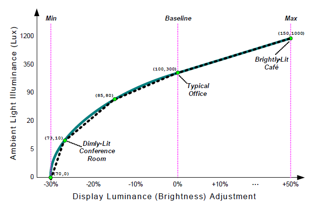
Fig. 9.1 A five-point ALS Response Curve
The figure above illustrates the use of five points to approximate an example response curve, where the dotted line represents an approximation of the desired response (solid curve). Extrapolation of the values between these points is OS-specific - although for the purposes of this example we’ll assume a piecewise linear approximation. The ALS response curve (_ALR) would be specified as follows:
Name(_ALR, Package() {
   Package{70, 0},    // Min      ( -30% adjust at 0 lux)
   Package{73, 10},   //          ( -27% adjust at 10 lux)
   Package{85, 80},   //          ( -15% adjust at 80 lux)
   Package{100,300},  // Baseline ( 0% adjust at 300 lux)
   Package{150,1000}  // Max      ( +50% adjust at 1000 lux)
})
Within this data set exist three points of particular interest: baseline, min, and max. The baseline value represents an ambient light illuminance value (in lux) for the environment where this system is most likely to be used. When the system is operating in this ambient environment the ALS policy will apply no (0%) adjustment to the default display brightness setting. For example, given a system with a 300 lux baseline, operating in a typical office ambient environment (~300 lux), configured with a default display brightness setting of 50% (e.g. 60 nits), the ALS policy would apply no backlight adjustment, resulting in an absolute display brightness setting of 60 nits.
Min and max are used to indicate cutoff points in order to prevent an over-zealous response by the ALS policy and to influence the policy’s mode of operation. For example, the min and max points from the figure above would be specified as (70,0) and (150,1000) respectively - where min indicates a maximum negative adjustment of 30% and max represents a maximum positive adjustment of 50%. Using a large display brightness adjustment for max allows an ALS response that approaches a fully-bright display (100% absolute) in very bright ambient environments regardless of the user’s display brightness preference. Using a small value for max (e.g. 0% @ 300 lux) would influence the ALS policy to limit the use of this technology solely as a power-saving feature (never brighten the display). Conversely, setting min to a 0% adjustment instructs ALS policy to brighten but never dim.
A minimum of two data points are required in the return package, interpreted as min and max. Note that the baseline value does not have to be explicitly stated; it can be derived from the response curve. Addition elements can be provided to fine-tune the response between these-points. The following figure illustrates the use of two data points to achieve a response similar to (but simpler than) that described in the five-point ALS response curve example.
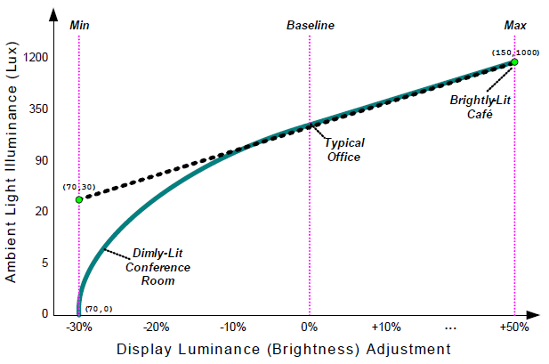
Fig. 9.2 A two-point ALS Response Curve
This example lacks an explicit baseline and includes a min with an ambient light value above 0 lux. The baseline can easily be extrapolated by ALS Policy (e.g. 0% adjustment at ~400 lux). All ambient light brightness settings below min (20 lux) would be treated in a similar fashion by ALS policy (e.g. -30% adjustment). This two-point response curve would be modeled as:
Name(_ALR, Package() {
   Package{70, 30},   // Min  ( -30% adjust at 30 lux)
   Package{150,1000}  // Max  ( +50% adjust at 1000 lux)
})
This model can be used to convey a wide range of ambient light to display brightness responses. For example, a transflective display - a technology where illumination of the display can be achieved by reflecting available ambient light, but also augmented in dimly-lit environments with a backlight - could be modeled as illustrated in the following figure.
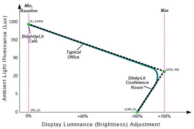
Fig. 9.3 Example Response Curve for a Transflective Display
This three-point approximation would result in an ALS response that allows the backlight to increase as the ambient lighting decreases. In this example, no backlight adjustment is needed in bright environments (1000+ lux), maximum backlight may be needed in dim environments (~30 lux), but a lower backlight setting may be used in a very-dark room (~0 lux) - resulting in an elbow around 30 lux. This response would be modeled in _ALR as follows:
Name(_ALR, Package() {
   Package{180, 0} ( +80% adjust at 0 lux)
   Package{200, 30},  // Max  (+100% adjust at 30 lux)
   Package{0, 1000},  // Min  ( 0% adjust at 1,000 lux)
})
Note the ordering of package elements: monotonically increasing from the lowest ambient light value (0 lux) to the highest ambient light value (1000 lux).
The transflective display example also highlights the need for non-zero values for the user’s display brightness preference - which we’ll refer to as the reference display brightness value. This requirement is derived from the model’s use of relative adjustments. For example, applying any adjustment to a 0% reference display brightness value always results in a 0% absolute display brightness setting. Likewise, using a very small reference display brightness (e.g. 5%) results in a muted response (e.g. +30% of 5% = 6.5% absolute). The solution is to apply a reasonably large value (e.g. 50%) as the reference display brightness setting - even in the case where no backlight is applied. This allows relative adjustments to be applied in a meaningful fashion while conveying to the user that the display is still usable (via reflected light) under typical ambient conditions.
The OS derives the user’s display brightness preference (this reference value) either from the Brightness Control Levels (_BCL) object or another OS-specific mechanism (see Section 9.3.8).
9.3.6. _ALP (Ambient Light Polling)
This optional object evaluates to a recommended polling frequency (in tenths of seconds) for this ambient light sensor. A value of zero - or the absence of this object when other ALS objects are defined - indicates that OSPM does not need to poll the sensor in order to detect meaningful changes in ambient light (the hardware is capable of generating asynchronous notifications).
The use of polling is allowed but strongly discouraged by this specification. OEMs should design systems that asynchronously notify OSPM whenever a meaningful change in the ambient light occurs–relieving the OS of the overhead associated with polling.
This value is specified as tenths of seconds. For example, a value of 10 would be used to indicate a 1 second polling frequency. As this is a recommended value, OSPM will consider other factors when determining the actual polling frequency to use.
Arguments:
None
Return Value:
An Integer containing the recommended polling frequency in tenths of seconds
0 - Polling by the host OS is not required
Other - The recommended polling frequency in tenths of seconds
9.3.7. Ambient Light Sensor Events
To communicate meaningful changes in ALS illuminance to OSPM, AML code should issue a Notify(als_device, 0x80) whenever the lux reading changes more than 10% (from the last reading that resulted in a notification). OSPM receives this notification and evaluates the _ALI control method to determine the current ambient light status. The OS then adjusts the display brightness based upon its ALS policy (derived from _ALR).
The definition of what constitutes a meaningful change is left to the system integrator, but should be at a level of granularity that provides an appropriate response without overly taxing the system with unnecessary interrupts. For example, an ALS configuration may be tuned to generate events for all changes in ambient light illuminance that result in a minimum ±5% display brightness response (as defined by _ALR).
To communicate meaningful changes in ALS color temperature to OSPM, AML code should issue a Notify(als_device, 0x81) whenever the lux reading changes more than 10% (from the last reading that resulted in a notification). OSPM receives this notification and evaluates the _ALT and _ALC control method to determine the current ambient light color temperature.
To communicate meaningful changes in ALS response to OSPM, AML code should issue a Notify(als_device, 0x82) whenever the set of points used to convey ambient light response has changed. OSPM receives this notification and evaluates the _ALR object to determine the current response points.
9.3.8. Relationship to Backlight Control Methods
The Brightness Control Levels (_BCL) method - described in section 0 - can be used to indicate user-selectable display brightness levels. The information provided by this method indicates the available display brightness settings, the recommended default brightness settings for AC and DC operation, and the absolute maximum and minimum brightness settings. These values indirectly influence the operation of the OSPM’s ALS policy.
Display brightness adjustments produced by ALS policy are relative to the current user backlight setting, and the resulting absolute value must be mapped (rounded) to one of the levels specified in _BCL. This introduces the requirement for fine-grain display brightness control in order to achieve a responsive ALS system - which typically materializes as a need for additional entries in the _BCL list in order to provide reasonable resolution to the OS (e.g. 3-10% granularity). Note that user brightness controls (e.g. hotkeys) are not required to make use of all levels specified in _BCL.
9.4. Control Method Lid Device
Platforms containing lids convey lid status (open / closed) to OSPM using a Control Method Lid Device.
To implement a control method lid device, AML code should issue a Notify(lid_device, 0x80) for the device whenever the lid status has changed. The _LID control method for the lid device must be implemented to report the current state of the lid as either opened or closed.
The lid device can support _PRW and _PSW methods to select the wake functions for the lid when the lid transitions from closed to opened.
The Plug and Play ID of an ACPI control method lid device is PNP0C0D.
Object |
Description |
|---|---|
_LID |
Returns the current status of the lid. |
9.4.1. _LID
Evaluates to the current status of the lid.
Arguments:
None
Return Value:
An Integer containing the current lid status:
0 - The lid is closed Non-zero - The lid is open
9.5. Control Method Power and Sleep Button Devices
The system’s power or sleep button can either be implemented using the fixed register space as defined in Console Buttons or implemented in AML code as a control method power button device. In either case, the power button override function or similar unconditional system power or reset functionality is still implemented in external hardware.
To implement a control method power-button or sleep-button device, implement AML code that delivers two types of notifications concerning the device. The first is Notify(Object, 0x80) to signal that the button was pressed while the system was in the S0 state to indicate that the user wants the machine to transition from S0 to some sleeping state. The other notification is Notify(Object, 0x2) to signal that the button was pressed while the system was in an S1 to S4 state and to cause the system to wake. When the button is used to wake the system, the wake notification (Notify(Object, 0x2)) must occur after OSPM actually wakes, and a button-pressed notification (Notify(Object, 0x80)) must not occur.
The Wake Notification indicates that the system is awake because the user pressed the button and therefore a complete system resume should occur (for example, turn on the display immediately, and so on).
9.6. Generic Container Device
A generic container device is a bridge that does not require a special OS driver because the bridge does not provide or require any features not described within the normal ACPI device functions. The resources the bridge requires are specified via normal ACPI resource mechanisms. Device enumeration for child devices is supported via ACPI namespace device enumeration and OS drivers require no other features of the bus. Such a bridge device is identified with the Plug and Play ID of PNP0A05 or PNP0A06.
A generic bus bridge device is typically used for integrated bridges that have no other means of controlling them and that have a set of well-known devices behind them. For example, a portable computer can have a “generic bus bridge” known as an EIO bus that bridges to some number of Super-I/O devices. The bridged resources are likely to be positively decoded as either a function of the bridge or the integrated devices. In this example, a generic bus bridge device would be used to declare the bridge then child devices would be declared below the bridge; representing the integrated Super-I/O devices.
9.7. ATA Controller Devices
There are two types of ATA Controllers: IDE controllers (also known as ATA controllers) and Serial ATA (SATA) controllers. IDE controllers are those using the traditional IDE programming interface, and may support Parallel ATA (P-ATA) or SATA connections. SATA controllers may be designed to operate in emulation mode only, native mode only, or they may be designed to support both native and non-native SATA modes. Regardless of the mode supported, SATA controllers are designed to work solely with drives supporting the Serial ATA physical interface. As described below, SATA controllers are treated similarly but not identically to traditional IDE controllers.
Platforms that contain controllers that support native and non-native SATA modes must take steps to ensure the proper objects are placed in the namespace for the mode in which they are operating.
Object |
Description |
Controller Type |
|---|---|---|
_GTF |
Optional object that returns the ATA task file needed to re-initialize the drive to boot up defaults. |
Both |
_GTM |
Optional object that returns the IDE controller timing information. |
IDE-only |
_STM |
Optional control method that sets the IDE controller’s transfer timing settings. |
IDE-only |
_SDD |
Optional control method that informs the platform of the type of device attached to a port. |
SATA-only |
9.7.1. Objects for Both ATA and SATA Controllers
9.7.1.1. _GTF (Get Task File)
This optional object returns a buffer containing the ATA commands used to restore the drive to boot up defaults (that is, the state of the drive after POST). The returned buffer is an array with each element in the array consisting of seven 8-bit register values (56 bits) corresponding to ATA task registers 1F1 thru 1F7. Each entry in the array defines a command to the drive.
Arguments:
None
Return Value:
A Buffer containing a byte stream of ATA commands for the drive
This object may appear under SATA port device objects or under IDE channel objects.
ATA task file array definition:
Seven register values for command 1
Reg values: (1F1, 1F2, 1F3, 1F4, 1F5, 1F6, 1F7)
Seven register values for command 2
Reg values: (1F1, 1F2, 1F3, 1F4, 1F5, 1F6, 1F7)
Seven register values for command 3
Reg values: (1F1, 1F2, 1F3, 1F4, 1F5, 1F6, 1F7)
Etc.
After powering up the drive, OSPM will send these commands to the drive, in the order specified. On SATA HBAs, OSPM evaluates _SDD before evaluating _GTF. The IDE driver may modify some of the feature commands or append its own to better tune the drive for OSPM features before sending the commands to the drive.
This Control Method is listed under each drive device object. OSPM must evaluate the _STM object or the _SDD object before evaluating the _GTF object.
Example of the return from _GTF:
Method(_GTF, 0x0, NotSerialized)
{
   Return(GTF0)
}
Name(GTF0, Buffer(0x1c)
{
   0x03, 0x00, 0x00, 0x00, 0x00, 0xa0, 0xef, 0x03, 0x00, 0x00, 0x00, 0x00,
   0xa0, 0xef, 0x00, 0x10, 0x00, 0x00, 0x00, 0xa0, 0xc6, 0x00, 0x00, 0x00,
   0x00, 0x00, 0xa0, 0x91
}
9.7.2. IDE Controller Device
Most device drivers can save and restore the registers of their device. For IDE controllers and drives, this is not true because there are several drive settings for which ATA does not provide mechanisms to read. Further, there is no industry standard for setting timing information for IDE controllers. Because of this, ACPI interface mechanisms are necessary to provide the operating system information about the current settings for the drive and channel, and for setting the timing for the channel.
OSPM and the IDE driver will follow these steps when powering off the IDE subsystem:
The IDE driver will call the _GTM control method to get the current transfer timing settings for the IDE channel. This includes information about DMA and PIO modes.
The IDE driver will call the standard OS services to power down the drives and channel.
As a result, OSPM will execute the appropriate _PS3 methods and turn off unneeded power resources.
To power on the IDE subsystem, OSPM and the IDE driver will follow these steps:
The IDE driver will call the standard OS services to turn on the drives and channel.
As a result, OSPM will execute the appropriate _PS0 methods and turn on required power resources.
The IDE driver will call the _STM control method passing in transfer timing settings for the channel, as well as the ATA drive ID block for each drive on the channel. The _STM control method will configure the IDE channel based on this information.
For each drive on the IDE channel, the IDE driver will run the _GTF to determine the ATA commands required to reinitialize each drive to boot up defaults.
The IDE driver will finish initializing the drives by sending these ATA commands to the drives, possibly modifying or adding commands to suit the features supported by the operating system.
The following shows the namespace for these objects:
\_SB               // System bus
   PCI0            // PCI bus
      IDE1         // First IDE channel
         _ADR      // Indicates address of the channel on the PCI bus
         _GTM      // Control method to get current IDE channel settings
         _STM      // Control method to set current IDE channel settings
         _PR0      // Power resources needed for D0 power state
         DRV1      // Drive 0
            _ADR   // Indicates address of master IDE device
            _GTF   // Control method to get task file
         DRV2      // Drive 1
            _ADR   // Indicates address of slave IDE device
            _GTF   // Control method to get task file
      IDE2         // Second IDE channel
         _ADR      // Indicates address of the channel on the PCI bus
         _GTM      // Control method to get current IDE channel settings
         _STM      // Control method to set current IDE channel settings
         _PR0      // Power resources needed for D0 power state
         DRV1      // Drive 0
            _ADR   // Indicates address of master IDE device
            _GTF   // Control method to get task file
         DRV2      // Drive 1
            _ADR   // Indicates address of slave IDE device
            _GTF   // Control method to get task file
The sequential order of operations is as follows:
Powering down
Call _GTM.
Power down drive (calls _PS3 method and turns off power planes).
Powering up
Power up drive (calls _PS0 method if present and turns on power planes).
Call _STM passing info from _GTM (possibly modified), with ID data from each drive.
Initialize the channel.
May modify the results of _GTF.
For each drive:
– Call _GTF.
– Execute task file (possibly modified).
9.7.2.1. IDE Controller-specific Objects
9.7.2.1.1. _GTM (Get Timing Mode)
This Control Method exists under each channel device object and returns the current settings for the IDE channel.
Arguments:
None
Return Value:
A Buffer containing the current IDE channel timing information block as described in the GTM Method Result Codes table below.
_GTM returns a buffer with the following format
Buffer (){
   PIO Speed 0  //DWORD
   DMA Speed 0  //DWORD
   PIO Speed 1  //DWORD
   DMA Speed 1  //DWORD
   Flags        //DWORD
}
Field |
Format |
Description |
|---|---|---|
PIO Speed 0 |
DWORD |
The PIO bus-cycle timing for drive 0 in nanoseconds. 0xFFFFFFFF indicates that this mode is not supported by the channel. If the chipset cannot set timing parameters independently for each drive, this field represents the timing for both drives. |
DMA Speed 0 |
DWORD |
The DMA bus-cycle for drive 0 timing in nanoseconds. If bit 0 of the Flags register is set, this DMA timing is for UltraDMA mode, otherwise the timing is for multi-word DMA mode. 0xFFFFFFFF indicates that this mode is not supported by the channel. If the chipset cannot set timing parameters independently for each drive, this field represents the timing for both drives. |
PIO Speed 1 |
DWORD |
The PIO bus-cycle timing for drive 1 in nanoseconds. 0xFFFFFFFF indicates that this mode is not supported by the channel. If the chipset cannot set timing parameters independently for each drive, this field must be 0xFFFFFFFF. |
DMA Speed 1 |
DWORD |
The DMA bus-cycle timing for drive 1 in nanoseconds. If bit 0 of the Flags register is set, this DMA timing is for UltraDMA mode, otherwise the timing is for multi-word DMA mode. 0xFFFFFFFF indicates that this mode is not supported by the channel. If the chipset cannot set timing parameters independently for each drive, this field must be 0xFFFFFFFF. |
Flags |
DWORD |
Mode flags Bit [0]: 1 indicates using UltraDMA on drive 0 Bit [1]: 1 indicates IOChannelReady is used on drive 0 Bit [2]: 1 indicates using UltraDMA on drive 1 Bit [3]: 1 indicates IOChannelReady is used on drive 1 Bit [4]: 1 indicates chipset can set timing independently for each drive Bits [31:5]: reserved (must be 0) |
9.7.2.1.2. _STM (Set Timing Mode)
This Control Method sets the IDE channel’s transfer timings to the setting requested. The AML code is required to convert and set the nanoseconds timing to the appropriate transfer mode settings for the IDE controller. _STM may also make adjustments so that _GTF control methods return the correct commands for the current channel settings.
This control method takes three arguments: Channel timing information (as described in Table 9-6), and the ATA drive ID block for each drive on the channel. The channel timing information is not guaranteed to be the same values as returned by _GTM; the OS may tune these values as needed.
Arguments:(3)
Arg0 - A Buffer containing a channel timing information block (described in Table 9-6)
Arg1 - A Buffer containing the ATA drive ID block for channel 0
Arg2 - A Buffer containing the ATA drive ID block for channel 1
Return Value:
None
The ATA drive ID block is the raw data returned by the Identify Drive ATA command, which has the command code “0ECh.” The _STM control method is responsible for correcting for drives that misreport their timing information.
9.7.3. Serial ATA (SATA) Controller Device
9.7.3.1. Definitions
- HBA
Host Bus Adapter
- Native SATA aware
Refers to system software (platform firmware, option ROM, operating system, etc) that comprehends a particular SATA HBA implementation and understands its programming interface and power management behavior.
- Non-native SATA aware
Refers to system software (platform firmware, option ROM, operating system, etc) that does not comprehend a particular SATA HBA implementation and does not understand its programming interface or power management behavior. Typically, non-native SATA aware software will use a SATA HBA’s emulation interface (e.g. task file registers) to control the HBA and access its devices.
- Emulation mode
Optional mode supported by a SATA HBA. Allows non-native SATA aware software to access SATA devices via traditional task file registers.
- Native mode
Optional mode supported by a SATA HBA. Allows native SATA aware software to access SATA devices via registers that are specific to the HBA.
- Hybrid Device
Refers to a SATA HBA that implements both an emulation and a native programming interface.
9.7.3.2. Overview
A SATA HBA differs from an IDE controller in a number of ways. First, it can save its complete device context. Second, it replaces IDE channels, which may support up to 2 attached devices, with ports, which support only a single attached device, unless a port multiplier is present. See the SATA spec at “Links to ACPI-Related Documents” ( http://uefi.org/acpi ) under the heading “SATA Specification”for more information. Finally, SATA does not require timing information from the platform, allowing a simplification in how SATA controllers are represented in ACPI. (_GTM and _STM are replaced by the simpler _SDD method.)
All ports, even those attached off a port multiplier, are represented as children directly under the SATA controller device. This is practical because the SATA specification does not allow a port multiplier to be attached to a port multiplier. Each port’s _ADR indicates to which root port they are connected, as well as the port multiplier location, if applicable (see Table 6.2)
Since this specification only covers the configuration of motherboard devices, it is also the case that the control methods defined in this section cannot be used to send taskfiles to devices attached via either an add-in SATA HBA, or attached via a motherboard SATA HBA, if used with a port multiplier that is not also on the motherboard.
The following shows an example SATA namespace:
\_SB - System bus
   PCI0 - PCI bus
      SATA - SATA Controller device
         ADR - Indicates address of the controller on the PCI bus
         PR0 - Power resources needed for D0 power state
         PRT0 - Port 0 device
            _ADR - Indicates physical port and port multiplier topology
            _SDD - Identify information for drive attached to this port
            _GTF - Control method to get task file
         PRTn - Port n device
            _ADR - Indicates physical port and port multiplier topology
            _SDD - Identify information for drive attached to this port
            _GTF - Control method to get task file
9.7.3.3. SATA controller-specific control methods
In order to ensure proper interaction between OSPM, the firmware, and devices attached to the SATA controller, it is a requirement that OSPM execute the _SDD and _GTF control methods when certain events occur. OSPM’s response to events must be as follows:
COMRESET, Initial OS load, device insertion, HBA D3 to D0 transition, asynchronous loss of signal:
OSPM sends IDENTIFY DEVICE or IDENTIFY PACKET DEVICE command to the attached device.
OS executes _SDD. _SDD control method requires 1 argument that consists of the data block received from an attached device as a result of a host issued IDENTIFY DEVICE or IDENTIFY PACKET DEVICE command.
After the _SDD method completes, the OS executes the _GTF method. Using the task file information provided by _GTF, the OS then sends the _GTF taskfiles to the attached device.
Device removal and HBA D0 to D3 transition:
No OSPM action required.
9.7.3.3.1. _SDD (Set Device Data)
This optional object is a control method that conveys to the platform the type of device connected to the port. The _SDD object may exist under a SATA port device object. The platform typically uses the information conveyed by the _SDD object to construct the values returned by the _GTF object.
OSPM conveys to the platform the ATA drive ID block, which is the raw data returned by the Identify (Packet) Device, ATA command (command code “0ech.”). Please see the ATA/ATAPI-6 specification for more details.
Arguments:(1)
Arg0 - A Buffer containing an ATA drive identify block, contents described by the ATA specification
Return Value:
None
9.8. Floppy Controller Device Objects
9.8.1. _FDE (Floppy Disk Enumerate)
Enumerating devices attached to a floppy disk controller is a time-consuming function. In order to speed up the process of floppy enumeration, ACPI defines an optional enumeration object that is defined directly under the device object for the floppy disk controller. It returns a buffer of five 32-bit values. The first four values are Boolean values indicating the presence or absence of the four floppy drives that are potentially attached to the controller. A non-zero value indicates that the floppy device is present. The fifth value returned indicates the presence or absence of a tape controller. Definitions of the tape presence value can be found in Tape Presence.
Arguments:
None
Return Value:
A Buffer containing a floppy drive information block, as decribed below:
Buffer (){
  Floppy 0 // Boolean DWORD
  Floppy 1 // Boolean DWORD
  Floppy 2 // Boolean DWORD
  Floppy 3 // Boolean DWORD
  Tape // DWORD - See the Tape Presence table below
}
Value |
Description |
|---|---|
0 |
Device presence is unknown or unavailable |
1 |
Device is present |
2 |
Device is never present |
>2 |
Reserved |
9.8.2. _FDI (Floppy Disk Information)
This object returns information about a floppy disk drive. This information is the same as that returned by the INT 13 Function 08H on IA-PCs.
Arguments:
None
Return Value:
A Package containing the floppy disk information as a list of Integers:
Package {
  Drive Number // Integer (BYTE)
  Device Type // Integer (BYTE)
  Maximum Cylinder Number // Integer (WORD)
  Maximum Sector Number // Integer (WORD)
  Maximum Head Number // Integer (WORD)
  disk_specify_1 // Integer (BYTE)
  disk_specify_2 // Integer (BYTE)
  disk_motor_wait // Integer (BYTE)
  disk_sector_siz // Integer (BYTE)
  disk_eot // Integer (BYTE)
  disk_rw_gap // Integer (BYTE)
  disk_dtl // Integer (BYTE)
  disk_formt_gap // Integer (BYTE)
  disk_fill // Integer (BYTE)
  disk_head_sttl // Integer (BYTE)
  disk_motor_strt // Integer (BYTE)
}
Package Element |
Element Object Type |
Actual Valid Data Width |
|---|---|---|
00 - Drive Number |
Integer |
BYTE |
01 - Device Type |
Integer |
BYTE |
02 - Maximum Cylinder Number |
Integer |
WORD |
03 - Maximum Sector Number |
Integer |
WORD |
04 - Maximum Head Number |
Integer |
WORD |
05 - Disk_specify_1 |
Integer |
BYTE |
06 - Disk_specify_2 |
Integer |
BYTE |
07 - Disk_motor_wait |
Integer |
BYTE |
08 - Disk_sector_siz |
Integer |
BYTE |
09 - Disk_eot |
Integer |
BYTE |
10 - Disk_rw_gap |
Integer |
BYTE |
11 - Disk_dtl |
Integer |
BYTE |
12 - Disk_formt_gap |
Integer |
BYTE |
13 - Disk_fill |
Integer |
BYTE |
14 - Disk_head_sttl |
Integer |
BYTE |
15 - Disk_motor_strt |
Integer |
BYTE |
9.8.3. _FDM (Floppy Disk Drive Mode)
This control method switches the mode (300 RPM or 360 RPM) of all floppy disk drives attached to this controller. If this control method is implemented, the platform must reset the mode of all drives to 300RPM mode after a Dx to D0 transition of the controller.
Arguments:(1)
Arg0 - An Integer containing the new drive mode
0 - Set the mode of all drives to 300 RPM mode
1 - Set the mode of all drives to 360 RPM mode
Return Value:
None
9.9. GPE Block Device
The GPE Block device is an optional device that allows a system designer to describe GPE blocks beyond the two that are described in the FADT. Control methods associated with the GPE pins of GPE block devices exist as children of the GPE Block device, not within the \_GPE namespace. Because GPE block devices are meant as an extension to the GPE blocks defined in the FADT, and that portion of the FADT is to be ignored in hardware-reduced ACPI, GPE block devices are not supported in hardware-reduced ACPI.
A GPE Block device consumes I/O or memory address space, as specified by its _PRS or _CRS child objects. The interrupt vector used by the GPE block does not need to be the same as the SCI_INT field. The interrupt used by the GPE block device is specified in the _CRS and _PRS methods associated with the GPE block. The _CRS of a GPE Block device may only specify a single register address range, either I/O or memory. This range contains two registers: the GPE status and enable registers. Each register’s length is defined as half of the length of the _CRS-defined register address range.
A GPE Block device must have a _HID or a _CID of “ACPI0006.”
Note
A system designer must describe the GPE block necessary to bootstrap the system in the FADT as a GPE0/GPE1 block. GPE Block devices cannot be used to implement these GPE inputs.*
A GPE Block Device must contain the _Lxx, _Exx, _Wxx, _CRS, _PRS, and _SRS methods required to use and program that block.
To represent the GPE block associated with the FADT, the system designer shouldinclude in the namespace a Device object with the ACPI0006 _HID that contains no _CRS, _PRS, _SRS, _Lxx, _Exx, or _Wxx methods. OSPM assumes that the first such ACPI0006 device is the GPE Block Device that is associated with the FADT GPEs. (See the example below).
// ASL example of a standard GPE block device

Device(\_SB.PCI0.GPE1) {
   Name(_HID, "ACPI0006")
   Name(_UID, 2)
   Name(_CRS, Buffer () {
      IO(Decode16, FC00, FC03, 4, 4,)
      IRQ( Level, ActiveHigh, Shared,) { 5 }
})

   Method(_L02) { ... }
   Method(_E07) { ... }
   Method(_W04) { ... }
}

// ASL example of a GPE block device that refers to the FADT GPEs.
// Cannot contain any \_Lxx, \_Exx, \_Wxx, \_CRS, \_PRS, or. \_SRS methods.
Device(\_SB.PCI0.GPE0) {
   Name(_HID,"ACPI0006")
   Name(_UID,1)
}
Notice that it is legal to replace the I/O descriptors with Memory descriptors if the register is memory mapped.
If the system must run any GPEs to bootstrap the system (for example, when Embedded Controller events are required), the associated block of GPEs must be described in the FADT. This register block is not relocatable and will always be available for the life of the operating system boot.
A GPE block associated with the ACPI0006 _HID can be stopped, ejected, reprogrammed, and so on. The system can also have multiple such GPE blocks.
9.9.1. Matching Control Methods for Events in a GPE Block Device
When a GPE Device raises an interrupt, OSPM executes a corresponding control method (see Queuing the matching control method for execution). These control methods for GPE Devices (of the form _Lxx, _Exx, and _Wxx) are not within the _GPE namespace. They are children of the GPE Block device.
For example:
Device(GPE5) {
   Name(_HID, "ACPI0006")
   Method(_L02) { ... }
   Method(_E07) { ... }
   Method(_W04) { ... }
}
9.10. Module Device
This optional device is a container object that acts as a bus node in a namespace. It may contain child objects that are devices or buses. The module device is declared using the ACPI0004 hardware identifier (HID).
If the module device contains a _CRS object, the bus described by this object is assumed to have these resources available for consumption by its child devices. If a _CRS object is present, any resources not produced in the module device’s _CRS object may not be allocated to child devices.
Providing a _CRS object is undesirable in some module devices. For example, consider a module device used to describe an add-in board containing multiple host bridges without any shared resource decoding logic. In this case the resource ranges available to the host bridges are not controlled by any entity residing on the add-in board, implying that a _CRS object in the associated module device would not describe any real feature of the underlying hardware. A module device must contain a _CRS object if the device contains any PCI host bridge devices.
To account for cases like this, the system designer may optionally omit the module device’s _CRS object. If no _CRS object is present, OSPM will assume that the module device is a simple container object that does not produce the resources consumed by its child devices. In this case, OSPM will assign resources to the child devices as if they were direct children of the module device’s parent object.
For an example with a module device _CRS object present, consider a Module Device containing three child memory devices. If the _CRS object for the Module Device contains memory from 2 GB through 6 GB, then the child memory devices may only be assigned addresses within this range.
Example:
Device (\_SB.NOD0) {
    Name (_HID, "ACPI0004")       // Module device
    Name (_UID, 0)
    Name (_PRS, ResourceTemplate() {
        WordIO (
            ResourceProducer,
            MinFixed,             // \_MIF
            MaxFixed,,,           // \_MAF
            0x0000,               // \_GRA
            0x0000,               // \_MIN
            0x7FFF,               // \_MAX
            0x0,                  // \_TRA
            0x8000)               // \_LEN
        DWordMemory (
            ResourceProducer,,    // For Main Memory + PCI
            MinNotFixed,          // _MIF
            MaxNotFixed,          // _MAF
            Cacheable,            // _MEM
            ReadWrite,            // _RW
            0x0FFFFFFF,           // _GRA
            0x40000000,           // _MIN
            0x7FFFFFFF,           // _MAX
            0x0,                  // _TRA
            0x00000000)           // _LEN
    })
    Method (_SRS, 1) { ... }
    Method (_CRS, 0) { ... }

    Device (MEM0) {               // Main Memory (256MB module)
        Name (_HID, EISAID("PNP0C80"))
        Name (_UID, 0)
        Method (_STA, 0) {        // If memory not present --> Return(0x00),
                                  // Else if memory is disabled --> Return(0x0D),
                                  // Else --> Return(0x0F)
        }
        Name (_PRS, ResourceTemplate () {
            DWordMemory (,,,,
                Cacheable,          // _MEM
                ReadWrite,          // _RW
                0x0FFFFFFF,         // _GRA
                0x40000000,         // _MIN
                0x7FFFFFFF,         // _MAX
                0x0,                // _TRA
                0x10000000)         // _LEN
            })
            Method (_CRS, 0) { ... }
            Method (_SRS, 1) { ... }
            Method (_DIS, 0) { ... }
        }
        Device (MEM1) {             // Main Memory (512MB module)
            Name (_HID, EISAID("PNP0C80"))
            Name (_UID, 1)
            Method (_STA, 0) {      // If memory not present --> Return(0x00)
                                    // Else if memory is disabled --> Return(0x0D)
                                    // Else --> Return(0x0F)
            }
            Name (_PRS, ResourceTemplate () {
                DWordMemory (,,,,
                    Cacheable,      // _MEM
                    ReadWrite,      // _RW
                    0x1FFFFFFF,     // _GRA
                    0x40000000,     // _MIN
                    0x7FFFFFFF,     // _MAX
                    0x0,            // _TRA
                    0x20000000)     // _LEN
                })
                Method (_CRS, 0) { ... }
                Method (_SRS, 1) { ... }
                Method (_DIS, 0) { ... }
            }
            Device (PCI0) { // PCI Root Bridge
                Name (_HID, EISAID("PNP0A03"))
                Name (_UID, 0)
                Name (_BBN, 0x00)
                Name (_PRS, ResourceTemplate () {
                    WordBusNumber (
                        ResourceProducer,
                        MinFixed,   // _MIF
                        MaxFixed,,  // _MAF
                        0x00,       // _GRA
                        0x00,       // _MIN
                        0x7F,       // _MAX
                        0x0,        // _TRA
                        0x80)       // _LEN
                    WordIO (
                        ResourceProducer,
                        MinFixed,   // _MIF
                        MaxFixed,,, // _MAF
                        0x0000,     // _GRA
                        0x0000,     // _MIN
                        0x0CF7,     // _MAX
                        0x0,        // _TRA
                        0x0CF8)     // _LEN
                    WordIO (
                        ResourceProducer,
                        MinFixed,   // _MIF
                        MaxFixed,,, // _MAF
                        0x0000,     // _GRA
                        0x0D00,     // _MIN
                        0x7FFF,     // _MAX
                        0x0,        // _TRA
                        0x7300)     // _LEN

                    DWordMemory (
                        ResourceProducer,,
                        MinNotFixed,   // _MIF
                        MaxNotFixed,   // _MAF
                        NonCacheable,  // _MEM
                        ReadWrite,     // _RW
                        0x0FFFFFFF,    // _GRA
                        0x40000000,    // _MIN
                        0x7FFFFFFF,    // _MAX
                        0x0,           // _TRA
                        0x00000000)    // _LEN
            })
            Method (_CRS, 0) { ... }
            Method (_SRS, 1) { ... }
    }
}
9.11. Memory Devices
Memory devices allow a platform to convey dynamic properties of memory to OSPM and are required when a platform supports the addition or removal of memory while the system is active or when the platform supports memory bandwidth monitoring and reporting (see Section 9.11.2). Memory devices may describe exactly the same physical memory that the System Address Map interfaces describe (see Section 15). They do not describe how that memory is, or has been, used. If a region of physical memory is marked in the System Address Map interface as AddressRangeReserved or AddressRangeNVS and it is also described in a memory device, then it is the responsibility of the OS to guarantee that the memory device is never disabled.
It is not necessary to describe all memory in the system with memory devices if there is some memory in the system that is static in nature. If, for instance, the memory that is used for the first 16 MB of system RAM cannot be ejected, inserted, or disabled, that memory may only be represented by the System Address Map interfaces. But if memory can be ejected, inserted, or disabled, or if the platform supports memory bandwidth monitoring and reporting, the memory must be represented by a memory device.
9.11.1. Address Decoding
Memory devices must provide a _CRS object that describes the physical address space that the memory decodes. If the memory can decode alternative ranges in physical address space, the devices may also provide _PRS, _SRS and _DIS objects. Other device objects may also apply if the device can be ejected.
9.11.2. Memory Bandwidth Monitoring and Reporting
During platform operation, an adverse condition external to the platform may arise whose remedy requires a reduction in the platform’s available memory bandwidth. For example, a server management controller’s detection of an adverse thermal condition or the need to reduce the total power consumption of platforms in the data center to stay within acceptable limits. Providing OSPM with knowledge of a platform induced reduction of memory bandwidth enables OSPM to provide more robust handling of the condition. The following sections describe objects OSPM uses to configure platform-based memory bandwidth monitoring and to ascertain available memory bandwidth when the platform performs memory bandwidth throttling.
9.11.2.1. _MBM (Memory Bandwidth Monitoring Data)
The optional _MBM object provides memory bandwidth monitoring information for the memory device.
Arguments:
None
Return Value:
A Package containing memory device status information as described in the MBM Package Details below.
Return Value Information:
_MBM evaluation returns a package of the following format:
Package (){
  Revision, // Integer
  WindowSize, // Integer DWORD
  SamplingInterval, // Integer DWORD
  MaximumBandwidth, // Integer DWORD
  AverageBandwidth, // Integer DWORD
  LowBandwidth, // Integer DWORD
  LowNotficationThreshold, // Integer DWORD
  HighNotificationThreshold // Integer DWORD
}
Field |
Format |
Description |
|---|---|---|
Revision |
Integer |
Current revision is: 0 |
Window Size |
Integer (DWORD) |
This field indicates the size of the averaging window (in seconds) that the platform uses to report average bandwidth. |
Sampling Interval |
Integer (DWORD) |
This field indicates the sampling interval (in seconds) that the platform uses to record bandwidth during the averaging window. |
Maximum Bandwidth |
Integer (DWORD) |
This field indicates the maximum memory bandwidth (in megabytes per second) for the memory described by this memory device. |
Average Bandwidth |
Integer (DWORD) |
This field indicates the moving average memory bandwidth (in percent) for the averaging window. |
Low Bandwidth |
Integer (DWORD) |
This field indicates the lowest memory bandwidth (in percent) recorded for the averaging window. |
Low Notification Threshold |
Integer (DWORD) |
The platform to issues a Notify (0x80) on the memory device when the moving average memory bandwidth value (in percent) falls below the value indicated by this field. |
High Notification Threshold |
Integer (DWORD) |
The platform to issues a Notify (0x81) on the memory device when the moving average memory bandwidth value (in percent) increases to or exceeds the value indicated by this field. |
9.11.2.2. _MSM (Memory Set Monitoring)
This optional object sets the memory bandwidth monitoring parameters described in Section 9.11.2.1 above.
Arguments(4)
Arg0 - WindowSize (Integer(DWORD)): indicates the window size in seconds.
Arg1 - SamplingInterval (Integer(DWORD)): indicates the sampling interval in seconds.
Arg2 - LowNotificationThreshold (Integer(DWORD)): indicates the low notification threshold in percent. Must be <= HighNotificationThreshold.
Arg3 - HighNotificationThreshold (Integer(DWORD)): indicates the high notification threshold in percent. Must be >= LowNotificationThreshold.
Return Value
An Integer (DWORD) containing a bit encoded result code as follows:
0x00000000 - Succeeded to set all memory bandwidth monitoring parameters.
Non-Zero - At least one memory bandwith monitoring parameter value could not be set as follows:
Bits |
Definition |
|---|---|
0 |
If clear indicates WindowSize was set successfully. If set, indicates invalid WindowSize argument. |
1 |
If clear indicates SamplingInterval was set successfully. If set, indicates invalid SamplingInterval argument. |
2 |
If clear indicates LowNotificationThreshold was set successfully. If set, indicates invalid LowNotificationThreshold argument. |
3 |
If clear indicates HighNotificationThreshold was set successfully. If set, indicates invalid HighNotificationThreshold argument. |
31:4 |
Reserved (must be 0) |
9.11.3. _OSC Definition for Memory Device
OSPM evaluates _OSC under the Memory Device to convey OSPM capabilities to the platform. Argument definitions are as follows
Arguments(4)
Arg0 - UUID (Buffer): 03B19910-F473-11DD-87AF-0800200C9A66
Arg1 - Revision ID (Integer): 1
Arg2 - Count of Entries in Arg3 (Integer): 2
Arg3 - DWORD capabilities (Buffer):
First DWORD: Described in Section 6.2.10
Second DWORD: See Section 6.4.3.5.2.
Return Value
A Buffer containing platform capabilities
Bits |
Field Name |
Definition |
|---|---|---|
0 |
Memory Bandwidth Change Notifications |
This bit is set if OSPM supports the processing of memory bandwidth change notifications. If the platform supports the ability to issue a notification when Memory Bandwidth changes, it may only do so after _OSC has been evaluated with this bit set. _OSC evaluation with this bit clear will cause the platform to cease issuing notifications if previously enabled. |
31:1 |
Reserved (must be 0) |
Return Value Information
Capabilities Buffer (Buffer) - The platform acknowledges the Capabilities Buffer by returning a buffer of DWORDs of the same length. Set bits indicate acknowledgement and cleared bits indicate that the platform does not support the capability.
9.11.4. Example: Memory Device
Scope (\_SB){
    Device (MEM0) {
        Name (_HID, EISAID ("PNP0C80"))
        Name (_CRS, ResourceTemplate () {
            QWordMemory
                ResourceConsumer,
                ,
                MinFixed,
                MaxFixed,
                Cacheable,
                ReadWrite,
                0xFFFFFFF,
                0x10000000,
                0x30000000,
                0,
                ,,)
            }
        }
    }
9.12. _UPC (USB Port Capabilities)
This optional object is a method that allows the platform to communicate to the operating system, certain USB port capabilities that are not provided for through current USB host bus adaptor specifications (e.g. UHCI, OHCI and EHCI). If implemented by the platform, this object will be present for each USB port (child) on a given USB host bus adaptor; operating system software can examine these characteristics at boot time in order to gain knowledge about the system’s USB topology, available USB ports, etc. This method is applicable to USB root hub ports as well as ports that are implemented through integrated USB hubs.
Arguments
None
Return Value
A Package as described below
Return Value Information
Package {
   Connectable             // Integer (BYTE)
   Type                    // Integer (BYTE)
   Reserved0               // Integer
   Reserved1               // Integer)
}
Element |
Object Type |
Description |
|---|---|---|
Connectable |
Integer (BYTE) |
If this value is non-zero, then the port is connectable. If this value is zero, then the port is not connectable. |
Type |
Integer (BYTE) |
Specifies the host connector type. It is ignored by OSPM if the port is not user visible: 0x00: Type ‘A’ connector 0x01: Mini-AB connector 0x02: ExpressCard 0x03: USB 3 Standard-A connector 0x04: USB 3 Standard-B connector 0x05: USB 3 Micro-B connector 0x06: USB 3 Micro-AB connector 0x07: USB 3 Power-B connector 0x08: Type C connector - USB2-only 0x09: Type C connector - USB2 and SS with Switch 0x0A: Type C connector - USB2 and SS without Switch 0x0B- 0xFE: Reserved 0xFF: Proprietary connector |
Reserved0 |
Integer |
This value is reserved for future use and must be zero. |
Reserved1 |
Integer |
This value is reserved for future use and must be zero. |
Additional Notes:
The definition of a connectable port is dependent on the implementation of the USB port within a particular platform. For example:
If a USB port is user visible (as indicated by the _PLD object) and connectable, then an end user can freely connect and disconnect USB devices to the USB port.
If a USB port is not user visible and is connectable, then an end user cannot freely connect and disconnect USB devices to the USB port. A USB device that is directly “hard-wired” to a USB port is an example of a USB port that is not user visible and is connectable.
If a USB port is not user visible and is not connectable, then the USB port is physically implemented by the USB host controller, but is not being used by the platform and therefore cannot be accessed by an end user.
A USB port cannot be specified as both visible and not connectable.
The pins of a Type-C connector support one USB2 signal pair (D+/D-) and two SuperSpeed signal pairs (SSTXp1/SSTXn1 and SSRXp2/SSRXn2). The use of two SS signal pairs allows the CC wire and USB SuperSpeed data bus wires to be used for signaling within the cable track without regard to the orientation and twist of the cable.
Type C connector - USB2 USB2-only receptacles
These only implement the USB2 signal pair, and do not implement the SS signal pairs.
Type C connector - USB2 and SS with Switch receptacles
These implement the USB2 signal pair, and a Functional Switch with a physical Multiplexer that is used to dynamically connect one of the two receptacle SuperSpeed signal pairs to a single USB Host Controller port as function of the Type-C plug orientation.
Type C connector - USB2 and SS *without* Switch receptacles
These implement the USB2 signal pair and a Functional Switch by connecting each receptacle SuperSpeed signal pair to a separate USB Host Controller port.
Note
See the USB Type-C Specification at https://www.usb.org/documents for more information.
Example
The following is an example of a port characteristics object implemented for a USB host controller’s root hub where:
Three Ports are implemented; Port 1 is not user visible/not connectable and Ports 2 and 3 are user visible and connectable.
Port 2 is located on the back panel
Port 3 has an integrated 2 port hub. Note that because this port hosts an integrated hub, it is therefore not shareable with another host controller (e.g. If the integrated hub is a USB2.0 hub, the port can never be shared with a USB1.1 companion controller).
The ports available through the embedded hub are located on the front panel and are adjacent to one another.
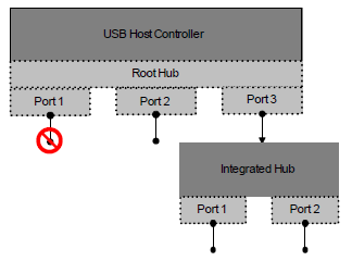
Fig. 9.4 USB ports
//
// Root hub device for this host controller.
// This controller implements 3 root hub ports.
//
Device( RHUB) {
   Name( \_ADR, 0x00000000)         // Value of 0 is reserved for root HUB
   //
   // Root hub, port 1
   //
   Device( PRT1) {
      // Address object for port 1. This value must be 1.
      Name( \_ADR, 0x00000001)
      // USB port capabilities object. This object returns the system
      // specific USB port configuration information for port number 1
      // Because this port is not connectable it is assumed to be not visible.
      // Therefore a \_PLD descriptor is not required.
      Name( \_UPC, Package(){
         0x00,                      // Port is not connectable
         0xFF,                      // Connector type (N/A for non-visible ports)
         0x00000000,                // Reserved 0 - must be zero
         0x00000000})               // Reserved 1 - must be zero
   }                                // Device( PRT1)
   //
   // Root Hub, Port 2
   //
   Device( PRT2) {
      // Address object for port 2. This value must be 2
      Name(_ADR, 0x00000002)
      Name( \_UPC, Package(){
         0xFF,                      // Port is connectable
         0x00,                      // Connector type - Type 'A'
         0x00000000,                // Reserved 0 - must be zero
         0x00000000})               // Reserved 1 - must be zero
                                    // provide physical port location info
      Name( \_PLD, Package(1) {
         Buffer(0x14) {
            0x82,0x00,0x00,0x00,    // Revision 2, Ignore color
                                    // Color (ignored), width and height not
            0x00,0x00,0x00,0x00,    // required as this is a standard USB 'A' type
                                    // connector
            0x69,0x0c,0x00,0x00,    // User visible, Back panel, Vertical
                                    // Center, shape = vert. rectangle
            0x03,0x00,0x00,0x00,    // ejectable, requires OPSM eject assistance
            0xFF,0xFF,0xFF,0xFF})}  // Vert. and Horiz. Offsets not supplied
   }                                // Device( PRT2)
   //
   // Root Hub, Port 3
   //
   Device( PRT3) {                  // This device is the integrated USB hub.
                                    // Address object for port 3. This value must be 3
      Name(_ADR, 0x00000003)
      // Because this port is not connectable it is assumed to be not visible.
      // Therefore a \_PLD descriptor is not required.
      Name( \_UPC, Package(){
         0xFF,                      // Port is connectable
         0xFF,                      // Connector type (N/A for non-visible ports)
         0x00000000,                // Reserved 0 - must be zero
         0x00000000})               // Reserved 1 - must be zero
         //
         // Integrated hub, port 1
         //
         Device( PRT1) {
         // Address object for the port. Because the port is implemented on
         // integrated hub port #1, this value must be 1
         Name( \_ADR, 0x00000001)
         // USB port characteristics object. This object returns the system
         // specific USB port configuration information for integrated hub port
         // number 1
         Name( \_UPC, Package(){
            0xFF,                   // Port is connectable
            0x00,                   // Connector type - Type 'A'
            0x00000000,             // Reserved 0 - must be zero
            0x00000000})            // Reserved 1 - must be zero
                                    // provide physical port location info
         Name( \_PLD, Package(1) {
            Buffer(0x14) {
            0x82,0x00,0x00,0x00,,   // Revision 2, Ignore color
                                    // Color (ignored), width and height not
            0x00,0x00,0x00,0x00,    // required as this is a standard USB 'A' type
                                    // connector
            0xa1,0x10,0x00,0x00,    // User visible, front panel, Vertical
                                    // lower, horz. Left, shape = horz. rectangle
            0x03,0x00,0x00,0x00,    // ejectable, requires OPSM eject assistance
            0xFF,0xFF,0xFF,0xFF})}  // Vert. and Horiz. Offsets not supplied
         }                          // Device( PRT1)
         //
         // Integrated hub, port 2
         //
         Device( PRT2) {            // Address object for the port. Because the port
                                    // is implemented on integrated hub port #2,
                                    // this value must be 2
            Name( \_ADR, 0x00000002)
                                    // USB port characteristics object. This object
                                    // returns the system-specific USB port configuration
                                    // information for integrated hub port number 2
            Name( \_UPC, Package(){
               0xFF,                // Port is connectable
               0x00,                // Connector type - Type 'A'
               0x00000000,          // Reserved 0 - must be zero
               0x00000000})         // Reserved 1 - must be zero
            Name( \_PLD, Package(1) {
               Buffer(0x14) {
               0x82,0x00,0x00,0x00, // Revision 2, Ignore color
                                    // Color (ignored), width and height not
               0x00,0x00,0x00,0x00, // required as this is a standard USB 'A' type
                                    // connector
               0xa1,0x12,0x00,0x00, // User visible, front panel, Vertical
                                    // lower, horz. right, shape = horz. rectangle
               0x03,0x00,0x00,0x00, // ejectable, requires OPSM eject assistance
               0xFF,0xFF,0xFF,0xFF}) // Vert. and Horiz. Offsets not supplied
      }                             // Device( PRT2)
   }                                // Device( PRT3)
}                                   // Device( RHUB)
9.12.1. USB 2.0 Host Controllers and _UPC and _PLD
Platforms implementing USB2.0 host controllers that consist of one or more USB1.1 compliant companion controllers (e.g. UHCI or OHCI) must implement a _UPC and a _PLD object for each port USB port that can be routed between the EHCI host controller and its associated companion controller. This is required because a USB Port Capabilities object implemented for a port that is a child of an EHCI host controller may not be available if the OSPM disables the parent host controller. For example, if root port 1 on an EHCI host controller is routable to root port 1 on its companion controller, then the namespace must provide a _UPC and a _PLD object under each host controller’s associated port 1 child object.
Example
Scope(\_SB) {
...
Device(PCI0) {
...
                     // Host controller (EHCI)
Device( USB0) {
                     // PCI device#/Function# for this HC. Encoded as specified in the ACPI
                     // specification
Name(_ADR, 0xyyyyzzzz)
                     // Root hub device for this HC #1.
Device(RHUB) {
Name(_ADR, 0x00000000) // must be zero for USB root hub
                     // Root hub, port 1
Device(PRT1) {

Name(_ADR, 0x00000001)
                     // USB port configuration object. This object returns the system
                     // specific USB port configuration information for port number 1
                     // Must match the \_UPC declaration for USB1.RHUB.PRT1 as it is this
                     // host controller's companion
Name( \_UPC, Package(){
   0xFF,             // Port is connectable
   0x00,             // Connector type - Type 'A'
   0x00000000,       // Reserved 0 - must be zero
   0x00000000})      // Reserved 1 - must be zero

                     // provide physical port location info for port 1
                     // Must match the \_UPC declaration for USB1.RHUB.PRT1 as it is this
                     // host controller's companion
   Name( \_PLD, Package(1) {
      Buffer(0x14) {
      0x82,0x00,0x00,0x00, // Revision 2, Ignore color
                     // Color (ignored), width and height not
      0x00,0x00,0x00,0x00, // required as this is a standard USB 'A'
                     // type connector

      0xa1,0x10,0x00,0x00, // User visible, front panel, Vertical
                     // lower, horz. Left, shape = horz. Rect.
      0x03,0x00,0x00,0x00, // ejectable, needs OPSM eject assistance
            0xFF,0xFF,0xFF,0xFF})} // Vert. and Horiz. Offsets not supplied

   }                 // Device( PRT1)
                     //
                     // Define other ports, control methods, etc
   ...
   ...
   }                 // Device( RHUB)
   }                 // Device( USB0)

                     // Companion Host controller (OHCI or UHCI)
   Device( USB1) {
                     // PCI device#/Function# for this HC. Encoded as specified in the ACPI
                     // specification
   Name(_ADR, 0xyyyyzzzz)
                     // Root hub device for this HC #1.
   Device(RHUB) {
   Name(_ADR, 0x00000000) // must be zero for USB root hub
                     // Root hub, port 1
   Device(PRT1) {
   Name(_ADR, 0x00000001)
                     // USB port configuration object. This object returns the system
                     // specific USB port configuration information for port number 1
                     // Must match the \_UPC declaration for USB0.RHUB.PRT1 as this host
                     // controller is a companion to the EHCI host controller
                     // provide physical port location info for port 1
   Name( \_UPC, Package(){
   0xFF,             // Port is connectable
   0x00,             // Connector type - Type 'A'
   0x00000000,       // Reserved 0 - must be zero
   0x00000000})      // Reserved 1 - must be zero

                     // Must match the \_PLD declaration for USB0.RHUB.PRT1 as this host
                     // controller is a companion to the EHCI host controller
   Name( \_PLD, Package(1) {
      Buffer( 0x14) {
      0x82,0x00,0x00,0x00, // Revision 2, Ignore color
                     // Color (ignored), width and height not
      0x00,0x00,0x00,0x00, // required as this is a standard USB 'A'
                     // type connector

      0xa1,0x10,0x00,0x00, // User visible, front panel, Vertical
                     // lower, horz. Left, shape = horz. Rect.
      0x03,0x00,0x00,0x00, // ejectable, requires OPSM eject assistance
            0xFF,0xFF,0xFF,0xFF})} // Vert. and Horiz. Offsets not supplied
   }                 // Device( PRT1)
                     //
                     // Define other ports, control methods, etc
   ...
   ...
   }                // Device( RHUB)
   }                // Device( USB1)
   }                // Device( PCI0)
   }                // Scope( \_\SB)
9.13. PC/AT RTC/CMOS Devices
Most computers contain an RTC device which also contains battery-backed RAM represented as a linear array of bytes. There is a standard mechanism for accessing the first 64 bytes of non-volatile RAM in devices that are compatible with the Motorola RTC/CMOS device that was in the IBM PC/AT. Newer devices usually contain at least 128 bytes of battery-backed RAM. New PNP IDs were assigned for these devices.
Certain bytes within the battery-backed RAM have pre-defined values. In particular, the time, date, month, year, century, alarm time and RTC periodic interrupt are read-only.
9.13.1. PC/AT-compatible RTC/CMOS Devices (PNP0B00)
The standard PC/AT-compatible RTC/CMOS device is denoted by the PnP ID PNP0B00. If an ACPI platform uses a device that is compatible with this device, it may describe this in its ACPI namespace. ASL may then read and write this as a linear 64-byte array. If PNP0B00 is used, ASL and ACPI operating systems may not assume that any extensions to the CMOS exist.
Note
This means that the CENTURY field in the Fixed ACPI Description Table may only contain values between 0 and 63.
Example:
The following is an example of how this device could be described:
Device (RTC0) {
   Name(_HID, EISAID("PNP0B00"))
   Name (_FIX, Package(1) { EISAID("PNP0B00") } )
   Name(_CRS, ResourceTemplate() {
      IO(Decode16, 0x70, 0x70, 0x1, 0x2)
   }

   OperationRegion(CMS1, SystemCMOS, 0, 0x40)

   Field(CMS1, ByteAcc, NoLock, Preserve) {
      CM00, 8,
      , 256,
      CM01, 8,
      CM02, 16,
      , 216,
      CM03, 8
   }
}
9.13.2. Intel PIIX4-compatible RTC/CMOS Devices (PNP0B01)
The Intel PIIX4 contains an RTC/CMOS device that is compatible with the one in the PC/AT. But it contains 256 bytes of non-volatile RAM. The first 64 bytes are accessed via the same mechanism as the 64 bytes in the PC/AT. The upper 192 bytes are accessed through an interface that is only used on Intel chips. (See the Intel® 82371AB PIIX4 specification for details.)
Any platform containing this device or one that is compatible with it may use the PNP ID PNP0B01. This will allow an ACPI-compatible OS to recognize the RTC/CMOS device as using the programming interface of the PIIX4. Thus, the array of bytes that ASL can read and write with this device is 256 bytes long.
Note
This also means that the CENTURY field in the Fixed ACPI Description Table may contain values between 0 and 255.
Example:
This is an example of how this device could be described:
Device (RTC0) {
   Name(_HID, EISAID("PNP0B01"))

Name (_FIX, Package(1) {
EISAID("PNP0B01") }
)
   Name(_CRS, ResourceTemplate() {
      IO(Decode16, 0x70, 0x70, 0x1, 0x2)
      IO(Decode16, 0x72, 0x72, 0x1, 0x2)
   }
   OperationRegion(CMS1, SystemCMOS, 0, 0x100)

   Field(CMS1, ByteAcc, NoLock, Preserve) {
      AccessAs(ByteAcc, 0),
      CM00, 8,
      ,256,
      CM01, 8,
      CM02, 16,
      , 224,
      CM03, 8,
      , 184,
      CENT, 8
}
9.13.3. Dallas Semiconductor-compatible RTC/CMOS Devices (PNP0B02)
Dallas Semiconductor RTC/CMOS devices are compatible with the one in the PC/AT, but they contain 256 bytes of non-volatile RAM or more. The first 64 bytes are accessed via the same mechanism as the 64 bytes in the PC/AT. The upper bytes are accessed through an interface that is only used on Dallas Semiconductor chips.
Any platform containing this device or one that is compatible with it may use the PNP ID PNP0B02. This will allow an ACPI-compatible OS to recognize the RTC/CMOS device as using the Dallas Semiconductor programming interface. Thus, the array of bytes that ASL can read and write with this device is 256 bytes long.
Description of these devices is similar to the PIIX4 example above, and the CENTURY field of the FADT may also contain values between 0 and 255.
9.14. User Presence Detection Device
The following section illustrates the operation and definition of the control method-based User Presence Detection (UPD) device.
The user presence detection device can optionally support power management objects (e.g. _PS0, _PS3) to allow the OS to manage the device’s power consumption.
The Plug and Play ID of an ACPI control method user presence detection device is ACPI000F.
Object |
Description |
|---|---|
_UPD |
The current user presence detection reading. [Required] |
_UPP |
User presence detection polling frequency in tenths of seconds. [Optional] |
9.14.1. _UPD (User Presence Detect)
This control method returns the user presence detection reading, indicating whether or not the user is currently present from the perspective of this sensor. Three states are currently defined for UPD sensor readings: absent, present, and unknown, represented by the values 0x00, 0x01, and 0xFF respectively. The unknown state is used to convey that the sensor is currently unable to determine user presence due to some environmental or other transient factor. All other values are reserved.
Arguments:
None
Return Value:
An Integer containing the user presence code:
0x00 - Absent: A user is not currently detected by this sensor.
0x01 - Present: A user is currently detected by this sensor.
0xFF - Unknown: The sensor is currently unable to determine if a user is present or absent.
9.14.2. _UPP (User Presence Polling)
This optional object evaluates to a recommended polling frequency (in tenths of seconds) for this user presence sensor. A value of zero - or the absence of this object when other UPD objects are defined - indicates that the OS does not need to poll the sensor in order to detect meaningful changes in user presence (the hardware is capable of generating asynchronous notifications).
Arguments:
None
Return Value:
An Integer containing the recommended polling frequency in tenths of seconds. A value of zero indicates that polling is not required.
The use of polling is allowed but strongly discouraged by this specification. OEMs should design systems that asynchronously notify OSPM whenever a meaningful change in user presence occurs–relieving the OS of the overhead associated with polling.
This value is specified as tenths of seconds. For example, a value of 10 would be used to indicate a 1 second polling frequency. As this is a recommended value, OSPM will consider other factors when determining the actual polling frequency to use.
9.14.3. User Presence Sensor Events
To communicate changes in user presence to OSPM, AML code should issue a Notify(upd_device, 0x80) whenever a change in user presence has occurred. The OS receives this notification and calls the _UPD control method to determine the current user presence status.
UPD notifications should be generated whenever a transition occurs between one of the user presence states (absent, present, or unknown) - but at a level of granularity that provides an appropriate response without overly taxing the system with unnecessary interrupts.
9.15. I/O APIC Device
This optional device describes a discrete I/O APIC device that is not bus enumerated (e.g., as a PCI device). Describing such a device in the ACPI namespace is only necessary if hot plug of this device is supported. If hot plug of this device is not supported, an MADT I/O APIC entry is sufficient to describe this device.
An I/O APIC device is an I/O unit that complies with either of the APIC interrupt models supported by ACPI. These interrupt models are described in Section 5.2.12.3 and Section 5.2.12.9.
If the device is an I/O unit that complies with the APIC interrupt model, it is declared using the ACPI000A identifier. If this device is an I/O unit that complies with the SAPIC interrupt model, it is declared using the ACPI000B identifier. If this device complies with both the APIC and SAPIC interrupt models (I/OxAPIC), it is declared using the ACPI0009 identifier.
An I/O APIC device declared using any of the above identifiers must contain a _GSB object to report its _GSB (Global System Interrupt Base). It must also contain a _CRS object that reports the base address of the I/O APIC device. The _CRS object is required to contain only one resource, a memory resource pointing to the I/O APIC register base.
Note
Because the _CRS and _GSB methods provide sufficient information, it is not necessary to provide _MAT under an I/O APIC device.
For an I/O APIC device that is described both in the MADT and in the namespace, the base address described in the MADT entry must be the same as the base address in the IO APIC device _CRS at boot time. OSPM must use the information from the MADT until such a time as the _CRS and _GSB methods in the namespace device can be processed. At this point OSPM must ignore the MADT entry.
9.16. Time and Alarm Device
The following sections define the operation and definition of the optional control method-based Time and Alarm device, which provides a hardware independent abstraction and a more robust alternative to the Real Time Clock (RTC) (See PC/AT RTC/CMOS Devices.)
The time capabilities of the time and alarm device maintain the time of day information across platform power transitions, and keep track of time even when the platform is turned off. It is expected that the time on the platform will be consistent when different firmware interfaces are used to query the platform time. For example, a UEFI call to get the time should return the same time as if the OSPM used the time and alarm device at the same point in time.
The Time and Alarm device can optionally support power management objects (e.g. _PS0, _PS3) to allow the OS to manage the device’s power consumption.
The Time and Alarm device must support control method _PRW for being enabled to wake up the system. It might support _DSW or _PSW to provide the functionality to enable or disable the device’s ability to wake a sleep system. On Hardware-reduced ACPI platforms, _PRW is only required if the device depends on ACPI-defined power resources. _PRW’s GPEInfo structure is ignored by OSPM. For enabling Wakeup, _DSW and _SxW are used, and the wakeup event is signaled by the GPIO-signaled ACPI event mechanism (see Section 5.6.5).
The Plug and Play ID of the Time and Wake Alarm device is ACPI000E.
Object |
Description |
|---|---|
_GCP |
Get the capabilities of the time and alarm device |
_GRT |
Get the Real time |
_SRT |
Set the Real time |
_GWS |
Get Wake status |
_CWS |
Clear Wake Status |
_STP |
Sets expired timer wake policy for the specified timer. |
_STV |
Sets the value in the specified timer. |
_TIP |
Returns the current expired timer policy setting of the specified timer. |
_TIV |
Returns the remaining time of the specified timer. |
9.16.1. Overview
The Time and Alarm device provides an alternative to the real time clock (RTC), which is defined as a fixed feature hardware device. The wake timers allow the system to transition from the S3 (or optionally S4/S5) state to S0 state after a time period elapses. In comparison with the Real Time Clock (RTC) Alarm, the Time and Alarm device provides a larger scale of flexibility in the operation of the wake timers, and allows the implementation of the time source to be abstracted from the OSPM.
Time and Alarm device provides the OSPM with a firmware abstraction of time and alarm services that can be applicable to a variety of hardware designs. The methods for setting and getting real time provide an alternative to the (RTC).
Time and Alarm devices that implement AC/DC wake service contain two programmable timers that can be configured to wake the system depending on the platform’s current power source (AC or DC) when the timers expire. The two timers, which are referred to as the AC timer and the DC timer, are independent in that they are individually programmable and applicable without interfering each other. Each of the timers can be programmed with the number of seconds to elapse from the time the timer is programmed until a wake is requested. When a timer expires, the Time and Alarm device decides whether to wake the system based on the current power source. If the current power source is consistent with the timer type that expired, a wake signal will be asserted. Otherwise, the wake signal will not be asserted.
Time and Alarm devices that implement the AC only (power independent) wake contain one programmable timer that can be configured to wake up the system regardless of the platform’s power source when the timer expires. To simplify the programming interface the AC wake will use the AC timer portion of the AC/DC wake; writes to the DC timer when AC only wake is supported will be ignored.
To simplify the programming interface for the time and alarm device, timer expiration events will persist. This means that if the OSPM programs a wake timer that expires before the OSPM completes the transition into S3 (or S4/S5 if supported) the time and alarm device will wake the system immediately after the OSPM completes the transition. Fig. 9.6 illustrates this behavior.
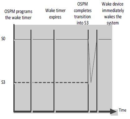
Fig. 9.5 Persistence of expired timer events
The time and alarm device will provide the OSPM with an interface to query the status of the wake timers and discover what timers have expired. This interface enables the OSPM to discover the wake source. The status of wake timers can be reset by setting the wake alarm; the OSPM may clear the alarm status using the clear wake status method. All expired wake timer must be cleared if the OSPM requires the platform to stay in S3 (S4/S5), otherwise the expired timers will immediately wake up the system.
For the AC/DC wake services, and in case the current power source is inconsistent with the timer type that expires, an expired timer wake policy value, in units of seconds, is defined that enables the time and alarm device to wake the system when the power source corresponding to the expired timer becomes active (wake either immediately, after some time period, or never). The expired timer wake policy is applicable only on devices that support AC/DC wake and only when the timer expires and the power source is not consistent with the timer type. The expired timer policy is applied in conjunction with expired timer persistence described earlier.
For example, if a mobile platform programs the AC timer to be 2 hours long and DC timer to be 4 hours long and then transitions from the S0 state to S3 state at 1:00 AM, the AC timer is set to expire at 3:00 AM and the DC timer is set to expire at 5:00 AM. For the AC Timer, a expired timer wake policy value is programmed as 60 seconds.
If the platform is unplugged from AC power at 1:40 AM and remains unplugged, the Time and Alarm Device will not wake up the system at 3:00 AM. If the platform remains on DC power until 5:00 AM when the DC timer expires, a wake signal will then be asserted. The following graph illustrates the above example.
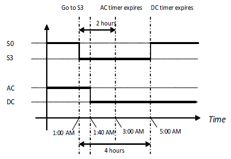
Fig. 9.6 System transitions with WakeAlarm — Timer
If the AC power is plugged in again at 4:00 AM, then the system will be woken up at 4:01 AM due to the AC expired timer wake policy value setting. The following graph illustrates this.
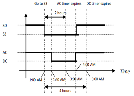
Fig. 9.7 System transitions with WakeAlarm — Policy
The Time and Alarm device can support a range of services, the OSPM evaluates the _GCP object to get the supported capabilities of the device. If the capabilities indicate that the device supports time services, the OSPM evaluates the _GRT and _SRT objects to get and set time respectively.
If alarm services are supported by the device, the OSPM evaluates the _STV object to program both the AC and DC timer values. The values, which are in units of seconds, indicate the elapsed time before the timer expires. OSPM evaluates the _TIV object to read the current AC and DC timer values (seconds remaining until expiration).
OSPM evaluates the _STP object to set timer policies for both the AC and DC timers OSPM reads the current timer policy by evaluating the _TIP object, which return policy settings for both the AC and DC timer.
The OSPM evaluates the _GWS object to identify expired timers that may have waked the platform. The OSPM must evaluate the _CWS object to clear any expired timer events that can prevent the system from performing a sleep transition according the expired timer wake policy, and the expired timer persistence described above.
The Time and Alarm device, if implemented with wake support, must support waking up the system from S3. Waking from S4/S5 support is optional.
9.16.2. _GCP (Get Capability)
This object is required and provides the OSPM with a bit mask of the device capabilities. The device can implement the time function in addition to the wake function. The capabilities bitmask will indicate to the OSPM what support is implemented. If the platform implements both AC and DC timers then it is capable of waking up based on the power source.
Arguments:(0)
Return Value:
A 32-bit integer containing a result bitmask as follows:
Bit [0] - 1 = AC wake implemented, 0 = not supported
Bit [1] - 1 = DC wake implemented, 0 = not supported
Bit [2] - 1 = Get/Set real time features implemented, 0 = not supported
Bit [3] - 1 = Real time accuracy in milliseconds, 0 = Real time accuracy in seconds
Bit [4] - 1 = _GWS returns correct values for wakes from S4/S5 caused by timer. 0 = not supported
Bit [5] - 1 = Wake supported from S4 on AC, 0 = Wake not supported from S4 on AC
Bit [6] - 1 = Wake supported from S5 on AC, 0 = Wake not supported from S5 on AC
Bit [7] - 1 = Wake supported from S4 on DC, 0 = Wake not supported from S4 on DC
Bit [8] - 1 = Wake supported from S5 on DC, 0 = Wake not supported from S5 on DC
Bit [9] to Bit [31] are reserved and must be 0.
9.16.3. _GRT (Get Real Time)
This object is required if the capabilities bit 2 is set to 1. The OSPM can use this object to get time. The return value is a buffer containing the time information as described below.
Arguments: (0)
Return Value:
A buffer containing the time information, in the following format:
Buffer(){
WORD Year;                 // 1900 - 9999
BYTE Month;                // 1 - 12
BYTE Day;                  // 1 - 31
BYTE Hour;                 // 0 - 23
BYTE Minute;               // 0 - 59
BYTE Second:               // 0 - 59
BYTE Valid;                // 0 - Time is not valid (request failed); 1 - Time is valid
WORD milliseconds,         // 1-1000
WORD TimeZone;             // -1440 to 1440 or 2047 (unspecified)
BYTE Daylight;
BYTE Pad2[3];              // Reserved, must be zero
}
9.16.4. _SRT (Set Real Time)
This object is required if the capabilities bit 2 is set to 1. The OSPM can use this object to set the time. The argument is a buffer containing the time information, as defined above.
Arguments: (1)
A buffer containing the time information, in the following format:
Buffer(){
WORD Year;                 // 1900 - 9999
BYTE Month;                // 1 - 12
BYTE Day;                  // 1 - 31
BYTE Hour;                 // 0 - 23
BYTE Minute;               // 0 - 59
BYTE Second;               // 0 - 59
BYTE Pad1;
WORD milliseconds,         // 1-1000
WORD TimeZone;             // -1440 to 1440 or 2047 (unspecified)
BYTE Daylight;
BYTE Pad2[3];              // Reserved, must be zero
}
Return Value:
An Integer:
0 - success 0xFFFFFFFF- Failed
Note
When entering daylight saving time, if the time is affected, but hasn’t been adjusted (DST = 1), use the new calculation:
The date/time should be increased by the appropriate amount.
The TimeZone should be decreased by the appropriate amount (EX: +480 changes to +420 when moving from PST to PDT).
The Daylight value changes to 3.
When exiting daylight saving time, if the time is affected and has been adjusted (DST = 3), use the new calculation:
The date/time should be decreased by the appropriate amount.
The TimeZone should be increased by the appropriate amount.
The Daylight value changes to 1.
9.16.5. _GWS (Get Wake alarm status)
This object is required and enables the OSPM to read the status of wake alarms. Expired wake timers will wake the platform even if the transition to a sleep state was completed after the wake timer has expired. This method enables the OSPM to retrieve the status of wake timers and clear any of them if needed.
Arguments: (1)
Arg0 - Timer Identifier (Integer (DWORD)): indicates the timer to be cleared:
0x00000000 - AC Timer
0x00000001 - DC Timer
Return Value:
An Integer (DWORD) containing current expired timers in bit field
Bit [0]- 1 = timer expired, 0 = timer did not expired
Bit [ 1]- 1= timer caused a platform wake, 0 = timer did not cause a platform wake
Bit [31:2] reserved and should be 0.
9.16.6. _CWS (Clear Wake alarm status)
This object is required and enables the OSPM to clear the status of wake alarms. Expired wake timers will wake the platform even if the transition to a sleep state was completed after the wake timer has expired. This method enables the OSPM to clear the status of expired wake timers.
Arguments:(1)
Arg0 - Timer Identifier (Integer (DWORD)): indicates the timer to be cleared:
0x00000000 - AC Timer
0x00000001 - DC Timer
Return Value:
An Integer (DWORD) containing current expired timer wake policy:
0x00000000 - Success
0x00000001 - Failure
9.16.7. _STP (Set Expired Timer Wake Policy)
This object is required and sets the expired timer wake policy. The policy is applied when a corresponding timer expired but the wake signal was not asserted as a result of the power source. The platform accumulates elapsed time on the power source and asserts the wake signal when the elapsed timer on the power source exceeds the expired timer wake policy value. Power source transitions do not reset the expired timer wake policy values. When the Wake Alarm device asserts the wake, the expired timer wake policy values of both the AC timer and DC timer are reset to 0xFFFFFFFF automatically by hardware.
Arguments:(2)
Arg0 - TimerIdentifier (Integer(DWORD)): indicates the timer to be set:
0x00000000 - AC Timer
0x00000001 - DC Timer
Arg1 - ExpiredTimerWakePolicy (Integer(DWORD)): indicates the expired timer wake policy:
0x00000000 - The timer will wake up the system instantly after the power source changes.
0x00000001 - 0xFFFFFFFE: time between the power source changes and the timer wakes up the system (in units of second).
0xFFFFFFFF - The timer will never wake up the system after the power source changes.
Return Value:
An Integer containing a result code as follows:
0x00000000 - Succeeded to set the expired timer wake policy.
0x00000001 - Failed to set the timer policy. Actual timer policy unknown.
9.16.8. _STV (Set Timer Value)
This object is required and sets the timer to the specified value. As defined in _TIV, the value indicates the number of seconds between the time when the timer is programmed and the time when it expires. When the Wake Alarm device asserts the wake signal, the timer value is automatically reset to 0xFFFFFFFF (disabled).
Arguments:(2)
Arg0 - TimerIdentifier (Integer (DWORD)): indicates the timer to be set:
0x00000000 - AC Timer
0x00000001 - DC Timer
Arg1 - TimerValue (Integer): indicates the value to be set.
Return Value:
An Integer containing a result code as follows:
0x00000000 - Succeeded to set timer value.
0x00000001 - Failed to set timer value. Actual timer value unknown.
9.16.9. _TIP (Expired Timer Wake Policy)
This object is required and returns the current expired timer wake policy setting of the specified timer.
Arguments:(1)
Arg0 - TimerIdentifier (Integer (DWORD)): indicates the timer to be read:
0x00000000 - AC Timer
0x00000001 - DC Timer
Return Value:
An Integer (DWORD) containing current expired timer wake policy:
0x00000000 - The timer will wake up the system instantly after the power source changes
0x00000001 - 0xFFFFFFFE: Time between the power source changes and the timer wakes up the system ( in units of seconds)
0xFFFFFFFF - The timer will never wake up the system after the power source changes
9.16.10. _TIV (Timer Values)
This object is required and returns the remaining time of the specified timer before it expires.
Arguments:(1)
Arg0 - TimerIdentifier (Integer(DWORD)): indicates the timer to be read:
0x00000000 - AC Timer
0x00000001 - DC Timer
Return Value:
An Integer containing the current timer value. A value of 0xFFFFFFFF indicates that the timer is disabled.
9.16.11. ACPI Wakeup Alarm Events
The Wake Alarm, device as a generic hardware, supports control methods _PSW and _PRW to wake up the system and issues a Notify(<device>, 0x2) on the wakeup alarm device.
9.16.12. Relationship to Real Time Clock Alarm
Though both of the devices support wakeup timers to wake up system from sleeping state, they work independently. The Real Time Clock Alarm is defined as a fixed feature hardware whereas Time and Alarm device is defined as a generic hardware and can replace or coexist with the real time clock. OSPM may choose which device to utilize to provide timed wake capability.
9.16.13. Time and Alarm device as a replacement to the RTC
The Time and Alarm device can be an alternative to the RTC on some platforms where the legacy RTC hardware is not available, on these platforms the OSPM can use the Time and Alarm device to obtain time and set wake alarms. For platforms that don’t require AC/DC wake service (e.g. a platform that have one power source only) the AC timer can be used to provide all the functions that were traditionally provided by the RTC. Using the capabilities object the Time and Alarm device can provide a scalable range of services to the OSPM.
9.16.14. Relationship to UEFI time source
The Time and Alarm device must be driven from the same time source as UEFI time services. This ensures that the platform has a consistent value of real time (time of day) and wake alarms. The OSPM can interact with this value using either ACPI or UEFI.
OSPM must use only one runtime interface to configure/query the platform alarm(s); undefined behavior may occur if the two wakeup interfaces are used on the same hardware.
If OSPM is trying to set an alarm using EFI runtime services, the alarm should be honored regardless of the power source (i.e. if the platform has an independent timer for each power source, they should both be configured with that alarm).
9.16.15. Example ASL code
The following ASL code serves as an example of how the Time and Alarm Device could be implemented. It is beyond the capability and the scope of this specification to provide a complete hardware implementation example.
Example 1: Define an ACPI Wake Alarm device
Device(\_SB.AWAK){
  Name(_HID, "ACPI000E")            //device ID
  Name(_PRW, Package(){...})        //enable or disable to wake up the system
  OperationRegion(CMOP, EmbeddedControl, ...)
  Field(CMOP, ByteAcc, ...){
    // timer status and policies
  }
  Method(_GCP) {
    Return (0x03)                   // Both AC and DC alarms are implemented;
                                    // Time capability is NOT supported
  }
  Method(_STP, 2){
    If(LEqual(Arg0, 0) {
      Store(Arg1, ...)              // Set AC timer policy
    }
    Else {
      Store(Arg1, ...)              // Set DC timer policy
    }
    Return(0)
  }
  Method(_TIP, 1){
    If(LEqual(Arg0, 1) {
      Store(..., Local0)            // Get DC timer policy
    }
    Else {
      Store(..., Local0)            // Get AC timer policy
    }
    Return (Local0)
  }
  Method(_STV, 2){
    If(LEqual(Arg0, 0) {
      Store(Arg1, ...)              // Set AC timer value
    }
    Else {
     Store(Arg1, ...)               //Set DC timer value
    }
    Return(0)
  }
  Method(_TIV, 1){
    If(LEqual(Arg0, 1) {
      Store(..., Local0)            //Get DC timer value
    }
    Else {
      Store(..., Local0)            //Get AC timer value
    }
    Return (Local0)
  }
  Method(_GWS, 1){
    If(LEqual(Arg0, 1) {
      Store(..., Local0)            //Get DC timer wake status
    }
    Else {
      Store(..., Local0)            //Get AC timer wake status
    }
    Return (Local0)
  }
  Method(_CWS, 2){
    If(LEqual(Arg0, 0) {
      Store(0, ...)                 //Clear AC Wake status
    }
    Else {
      Store(0, ...)                 //Clear DC Wake status
    }
    Return(0)
  }
}                                   // end of ACPI Wake Alarm device object
Scope(\_GPE) {                      // Root level event handlers
  Method(_Lxx){
    Store(One, ...)
    Notify(\_SB.AWA, 0x2)           //notify the OSPM of device wake
  }
} // end of \_GPE scope
Example 2: Define an ACPI Real Time device on a HW-Reduced ACPI platform
Device(\_SB.I2C1)                   //The controller used to access the RTC hardware
{
  Name (_HID, ...)
  ...                               // Other objects required for this I2C controller
  // Track status of SPB OpRegion availability for this controller
  Name(AVBL, 0)
  Method(_REG,2)
  {
    /* 9 is the OpRegion type for SPB. (8 == GPIO, etc) */
    If (Lequal(Arg0, 9))
    1{
      Store(Arg1, ^AVBL)
    }
  }
}
Device(\_SB.TAAD) {                 //The Time and Alarm Device
  Name (_HID, "ACPI000E")
  Scope(\_SB.I2C1)                  //OpRegion declaration must appear under the controller
  {
    OperationRegion(TOP1, GenericSerialBus, 254, 0x100)
    Field(TOP1, BufferAcc, NoLock, Preserve)
    {
      Connection(I2CSerialBusV2(0x4a,,400000,,"\\_SB.I2C1",,,,,)),
        //Connection to the controller for the following field accesses
      AccessAs(BufferAcc, AttribWord),  //AccessProtocol for the following field(s)
      Y, 8,
      AccessAs(BufferAcc, AttribByte),
      M, 8,
      D, 8,
      H, 8,
      Mi,8,
      S, 8,
      P, 8,
      AccessAs(BufferAcc, AttribWord),
      Ms, 8,
      Tz, 8,
      AccessAs(BufferAcc, AttribByte),
      Dl, 8,
      P2, 8
    }                                 // End of Field
  }                                   // End of Scope
  Method (_GCP, 0x0, NotSerialized)
  {
    Return(0x4)                       //Implements Real Time interface, but no alarms
  }
  Method(_GRT, 0x0, NotSerialized)
  {
    If(LNotEqual(\_SB.TC1.AVBL, 1))   // Verify that SPB OpRegion is available
                                      // for this access
    {
      Return(0)
    }
    Name(BUFF, Buffer(4){})           // Create SerialBus data buffer as BUFF
    CreateByteField(BUFF, 0x00, STAT) // STAT = Status (Byte)
    CreateWordField(BUFF, 0x02, DATA) // DATA = Data (Byte)
    Name(BUF2,Buffer(0x10){})         // Create buffer to hold the Real Time structure
                                      //as BUF2
    CreateWordField(BUF2, 0x0,Y)      // Year
    CreateByteField(BUF2,0x2,M)       // Month
    ...
    CreateByteField(BUF2,0xc,Dl)      // Dl
    CreateByteField(BUF2,0xd,P2)      // Pad2
    Store(\_SB.I2C1.Y, BUFF)          // Get each member from the OpRegion and store
                                      // in the structure
    Store(DATA,Y)
    Store(\_SB.I2C1.M, BUFF)
    Store(DATA,M)
    ...
    Store(\_SB.I2C1.Dl, BUFF)
    Store(DATA,Dl)
    Store(\_SB.I2C1.P2, BUFF)
    Store(DATA,P2)
    Return(BUF2)                        // Success -> return what was last in buffer
  }
  Method(_SRT,0x1, NotSerialized)
  {
    Name(BUFF, Buffer(4){})             // Create SerialBus data buffer as BUFF
    CreateByteField(BUFF, 0x00, STAT)   // STAT = Status (Byte)
    CreateWordField(BUFF, 0x02, DATA)   // DATA = Data (Byte)
      // Verify that SPB OpRegion is available for this access
    If(LNotEqual(\_SB.I2C1.AVBL, 1))
    {
       Return(0)
    }
    CreateWordField(Arg0,0x0,Y)         // Create Fields to access each member of the
                                        // input data
    ...
    CreateByteField(Arg0,0xd,P2)
    Store(Store(Y, \\_SB.I2C1.Y), BUFF) // Store each input member into the hardware,
                                        // and set the transaction status into BUFF
    If(LEqual(STAT, 0x00))              // transaction was *NOT* successful
    {
      Return(0xFFFFFFFF)
    }
    ...
    Store(Store(P2, \\_SB.I2C1.P2), BUFF)
    If(LEqual(STAT, 0x00))              // Transaction was \_NOT_successful
    {
      Return(0xFFFFFFFF)
    }
  }
  Name(_DEP, Package() {"\\_SB.I2C1"})  // Identify the OpRegion dependency for
                                        // this device
}                                       // End of Time and Alarm Device definition
9.17. Generic Buttons Device
The-Generic-Button device is a standard device for reporting button events via hardware interrupts, and mapping those interrupts to specific usages defined in the Human Interface Device (HID) specification. In order to express the functionality of a button to the OS, two pieces of information are required: Usage of the HID Control, and Usage of the HID Collection that the Control belongs to. A Usage is a combination of a Usage Page and Usage ID. For example, the Volume Up button is identified as the Volume Up Usage (Usage Page 0x0C, Usage Id 0xE9) in the Consumer Control Collection (Usage Page 0x0C, Usage Id 0x01).
The Plug and Play ID of the Generic Button device is ACPI0011.
Note
If the Power button is described using this device, it must also support the Power Button Override feature defined in Section 4.8.2.2.1.3.
Object |
Description |
|---|---|
_CRS |
Lists the resources consumed by the Generic Button device. Only interrupt resources (GpioInt() and Interrupt() ) are valid for this device. Each interrupt listed must signal one distinct button event. |
_DSD |
Provides a list of HID Button Descriptors, as defined by UUID FA6BD625-9CE8-470D-A2C7-B3CA36C4282E. Only HID 2-state button usages are valid for the descriptors returned for this device. |
Note
If there are more HID Button Descriptors returned by _DSD than there are interrupts listed in _CRS, behavior is OS-specific.
9.17.1. Button Interrupts
Interrupts for the Generic Buttons Device are required to be edge-triggered and not level-triggered since there is no interface defined for the driver to quiesce the interrupt line once the interrupt is received. The polarity (ActiveLow/High vs. ActiveBoth) of the interrupt is determined by the Usage Type of the HID Usage associated with the interrupt, as described in the table below.
Usage Type |
Interrupt Polarity |
Explanation |
|---|---|---|
OSC - One Shot Control |
ActiveHigh/ ActiveLow |
An interrupt should be triggered on a button press. This is for a toggle button. On every such event (interrupt), the Operating System will toggle the internal property of the entity that it controls. Example: Mute button |
MC - Momentary Control |
ActiveBoth |
An interrupt should be triggered on both the button press and release. Example: Left mouse button. |
RTC - Re-trigger Control |
ActiveBoth |
An interrupt should be triggered on both the button press and release. While the button is pressed, the Operating System will repeatedly re-execute the action that it would take when the button is pressed. Example: A Volume Up button when pressed and held, will repeatedly increment the Volume. |
OOC - On/Off Control |
ActiveHigh/ ActiveLow OR ActiveBoth |
ActiveHigh/ActiveLow polarity should be specified if implemented as a button that goes back to its initial state automatically. E.g. A Push Button or a spring-loaded Slider switch. Only one interrupt should be fired for press/release pair. Example: A spring-loaded Wireless Radio Slider Switch. ActiveBoth polarity should be specified if implemented as a button that stays in its state until the user moves it again. E.g. A button that stays in pressed state, or a Slider switch that sticks to its position. Example: Wireless Radio Slider Switch. |
9.17.2. Button Usages and Collections
The HID Usage tables have an extensive list of Standardized Usages for various kinds of buttons. Some of the common buttons found on Computing devices and their Usages are listed in the table below.
For the full list, see “HID Usage Tables”, available from “Links to ACPI-Related Documents” (http://uefi.org/acpi) under the heading “HID Usage Tables”.
Buttons are grouped under an HID Collection. Several HID Collections are commonly understood by Operating Systems, e.g., Keyboard Collection, Consumer Controls Collection, Wireless Radio Controls Collection, etc.
Button |
Usage Page / Usage |
Usage Type |
Interrupt Polarity |
Spec Reference |
|---|---|---|---|---|
Power |
Generic Desktop Page (0x01) System Power Down (0x01) |
OSC |
ActiveBoth * |
USB HID Usage Tables, version 1.2: see https://www.usb.org/hid, under the heading HID Usage Tables |
Volume Up |
Consumer Page (0x0C) Volume Increment (0xE9) |
RTC |
ActiveBoth |
USB HID Usage Tables, version 1.2: see https://www.usb.org/hid, under the heading HID Usage Tables |
Volume Down |
Consumer Page (0x0C) Volume Decrement (0xEA) |
RTC |
ActiveBoth |
USB HID Usage Tables, version 1.2: see https://www.usb.org/hid, under the heading HID Usage Tables |
Camera Shutter |
Camera Control Page (0x90) Camera Shutter (0x21) |
OSC |
Active High/ Active Low |
USB Review Request 49: Camera Controls - see https://www.usb.org/hid, under the heading Approved Usage Table Review Requests |
Display Brightness Up |
Consumer Page (0x0C) Display Brightnes s Increment (0x6F) |
RTC |
ActiveBoth |
USB Review Request 41: Display Brigtness Controls - see https://www.usb.org/hid, under the heading Approved Usage Table Review Requests |
Display Brightness Down |
Consumer Page (0x0C) Display Brightnes s Decrement (0x6F) |
RTC |
ActiveBoth |
USB Review Request 41: Display Brigtness Controls - see https://www.usb.org/hid, under the heading Approved Usage Table Review Requests |
Wireless Radio Button |
Generic Desktop Page (0x01) Wireless Radio Button (0xC6) |
OOC |
ActiveHigh/ ActiveLow |
USB Review Request 40: HID Radio On/Off Usages - see https://www.usb.org/hid, under the heading Approved Usage Table Review Requests |
Wireless Radio Slider Switch |
Generic Desktop Page (0x01) Wireless Radio Slider Switch (0xC8) |
OOC |
ActiveBoth |
USB Review Request 40: HID Radio On/Off Usages - see https://www.usb.org/hid, under the heading Approved Usage Table Review Requests |
Note
* The System Power Down Usage (Page:01, ID: 81) has Type OSC, although its interrupt must be ActiveBoth in order to allow drivers to perform functions based on “hold-down” timing. This is an exception to the Usage Type Rules for Interrupt Polarity (see Table 9.15).
9.17.3. Generic Buttons Device Example
Device(BTNS)
{
Name(_HID, "ACPI0011")
Name(_CRS, ResourceTemplate() {
            GpioInt(Edge, ActiveBoth...) {pin}   //Vol Down
            GpioInt(Edge, ActiveBoth...) {pin}   //Vol Up
            GpioInt(Edge, ActiveBoth,...) {pin}  //Power (MUST BE ACTIVEBOTH!)
      })
Name(_DSD, Package(2) {
      //UUID for HID Button Descriptors:
      //ToUUID("FA6BD625-9CE8-470D-A2C7-B3CA36C4282E"),
      //Data structure for this UUID:
Package() {
      Package(5) {
         0,         //Declare a Collection
         1,         //Unique ID for this collection
         0,         //It is a top-level collection
         0x0c,      //Usage Page ("Consumer")
         0x01       //Usage ("Consumer Control")
      },
      Package(5) {
         0,         //Declare another Collection
         2,         //Unique ID for this collection
         0,         //Also a top-level collection
         0x01,      // Usage Page ("Generic Desktop")
         0x80       //Usage ("System Control")
      },
Package(5) {
         1,         //Declare a Control
         0,         //Interrupt index in \_CRS for Vol Down
         1,         //In the "Consumer Control" collection
         0x0c,      //Usage Page ("Consumer")
         0xEA       //Usage ("Volume Decrement")
      },
      Package(5) {
         1,         //Declare another Control
         2,         //Interrupt index for the Power Button
         2,         //In the "System Control" collection
         0x01,      //Usage Page ("Generic Desktop")
         0x81       //Usage ("System Power Down")
      },
      Package(5) {
         1,         //Declare another Control
         1,         //Interrupt index for the Vol Up button
         1,         //In the "Consumer Control" collection
         0x0c,      //Usage Page ("Consumer")
         0xE9       //Usage ("Volume Increment")
      },
      Package(5) {
         1,         //Another Control
      0xFF,         //No Interrupt for this one... e.g. OS-
                    // specific signaling for Rotation Lock
         1,         //In the "Consumer Control" collection
         0x0C,      //Usage Page ("Consumer")
         0x245      //Usage ("AC Rotate")
      }
         }
})
}// End Device
9.18. NVDIMM Devices
9.18.1. Overview
In order to handle NVDIMMs, the OS must first be able to detect and enumerate the NVDIMMs. To facilitate the plug and play discovery of NVDIMM and driver loading, ACPI namespace devices are used.
9.18.2. NVDIMM Root Device
The NVDIMM root device is represented by an ACPI namespace device with an _HID of “ACPI0012” (see Section 6.1.5 and Table 5.172). If the platform supports NVDIMMs, then platform firmware shall report one NVDIMM root device in the SB scope (see Section 5.3.1). This device allows the OS to trigger enumeration of NVDIMMs through NFIT (see Table 5.107) at boot time and re-enumeration at root level via the Section 6.5.9 during runtime.
For each NVDIMM present or intended to be supported by platform, platform firmware also exposes an NVDIMM device (see Section 9.18.3) under the NVDIMM root device.
9.18.3. NVDIMM Device
Each NVDIMM is represented by an ACPI namespace device under the NVDIMM root device (see Section 9.18.2) with an _ADR (see Section 6.1.1) containing the NFIT Device Handle. The NFIT Device Handle is a 32-bit value. Bit [31] indicates the format of the NFIT Device Handle.
If Bit [31] is clear, then Bits [30:0] are defined as follows:
Bits [3:0] DIMM number within the memory channel
Bits [7:4] memory channel number within the memory controller
Bits [11:8] memory controller ID within the socket
Bits [15:12] socket ID within the node controller, if any
Bits [27:16] node controller ID, if any
Bits [31:28] Reserved
If Bit [31] is set, then Bits [30:0] are defined as follows:
Bits [30:0] platform unique value assigned by the platform firmware that is consistent across boots when the NVDIMM is in the same physical location but may change if the NVDIMM is in a different physical location.
NOTE: Bit 31 was introduced in ACPI Specification 6.4, so software compliant with previous versions of ACPI might parse the structure as if bit [31] is set to zero.
Table 5.163 defines NVDIMM Device Notification Values for an NVDIMM device.
Information about the Label Storage Area on the NVDIMM is provided by the _LSI (see Section 6.5.10.1) method. The OSPM uses the methods _LSR (see Section 6.5.10.2) and _LSW (see Section 6.5.10.3) to read and write to the Label Storage Area. The format of the Label Storage Area data is defined in UEFI.
9.18.4. Example
An example name space is shown below for a platform containing one NVDIMM:
Scope (\_SB){
Device (NVDR)                    // NVDIMM root device
{
   Name (_HID, "ACPI0012")
   Method (_STA) {...}
   Method (_FIT) {...}
   Method (_DSM, ...) {
   ...
   }
   Device (NVD)                  // NVDIMM device
   {
      Name(_ADR, h)              //where h is NFIT Device Handle for this NVDIMM
      Method (_DSM, ...) {
      ...
      }
   }
}
}
9.18.5. Loading NVDIMM drivers
While using ACPI namespace devices allows for OS handling of NVDIMMs in a standard manner, the format of the address ranges described by this scheme may still vary depending on the vendor (or even different NVDIMM version of the vendor). For example, the command and status values supported by a Block Control Window are vendor specific and possibly even vary for a given vendor.
The NVDIMM Control Region Structure (see Section 5.2.25.6) includes a Vendor ID, Device ID, and Revision ID. Because an NVDIMM could be a combination device consisting of different region types (e.g. Persistent Memory and Block), a Region Format Interface Code is also included to indicate the region type as well as the specific implementation within that type. This allows for variability across vendors as well as within vendor offerings.
These fields enable loading of drivers for managing the NVDIMM as well as for handling the address ranges supported by the NVDIMM. The Region Format Interface Code is used to load generic drivers for the following: management driver, persistent memory driver and block driver. A vendor specific driver for each of the above can be loaded by matching on Vendor ID, Device ID and Revision ID (in addition to the Region Format Interface Code).
Region Format Interface Code requirements shall be met by all compliant NVDIMMs. Any Vendor specific extensions are only allowed to extend on top of the Region Format Interface Code requirements.
It is assumed that the OSPM is capable of loading the Region Format Interface Code specific driver or vendor specific drivers based on such discovery. This scheme is as shown in the following figure.
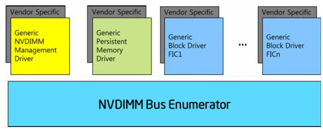
Fig. 9.8 Vendor/Device Specific Driver Loading
The Subsystem Vendor ID, Subsystem Device ID and Subsystem Revision ID fields allow selection of specific solution provider drivers that may span across devices from multiple vendors.
9.18.6. Hot Plug Support
The NVDIMM memory hot plug representation of the ACPI Name Space is described in this section. The NVDR device is the NVDIMM root device, the NVD1 and NVD2 are NVDIMM devices, the MEM0 is memory module device corresponding to the NVD1 and NVD2 devices. The _FIT method under NVDR device returns all NFIT entries including the hot added devices.
Device (NVDR)                       // Root device
{
   Name (_HID, "ACPI0012")
   Method (_STA) {...}
   Method (_FIT) {...}
   Method (_DSM, ...) {
   ...
   }
      Device (NVD1)                 // NVDIMM1
      {
         Name(_ADR, h1)             // where h1 is NFIT Device Handle for this NVDIMM1
         Method (_DSM, ...) {
         ...
         }
   }
   Device (NVD2)                    // NVDIMM2
   {
         Name(_ADR, h2)             // where h2 is NFIT Device Handle for this NVDIMM2
         Method (_DSM, ...) {
         ...
         }
   }
}

Device (MEM0)                       // Memory module
{
   Name (_HID, EISAID ("PNP0C80"))
   Method (_STA) {...}
   Method (_CRS) {...}
}

Scope (\_GPE)
{
   Method (_L00) {
      Notify (\_SB.NVDR, 0x80)      // Notify to NVDIMM root device
      Notify (\_SB.MEM0, 1)         // Device Check to Memory Module
   }
}
Hot Plugged memory is indicated to OS using ACPI Name Space device with PNPID of PNP0C80. The NFIT entries created by the hot plug NVDIMM are communicated by the ACPI Name Space device with ACPI0012.
NVDIMM hot add flow:
Prior to hot add of the NVDIMM, the corresponding ACPI Name Space devices, NVD1, NVD2 return an address from _ADR object (NFIT Device handle) which does not match any entries present in NFIT (either the static or from _FIT) indicating that the corresponding NVDIMM is not present. Further ACPI Name Space Device MEM0 returns _STA status of 0 indicating that the devices are not present, not enabled and not functioning.
On hot add:
a. Send Notify 0x80 to NVDR to cause NVDIMM bus driver to enumerate all the devices under the root hierarchy
b. NVDIMM bus driver evaluates the _FIT method under the NVDR device and identifies the changes to the NVDIMM devices present (by identifying new NFIT Device handles that have been added).
c. NVDIMM bus driver now finds matching entries for addresses returned by _ADR objects of NVD1 and NVD2 and loads the corresponding drivers.
d. Send Notify Device Check to MEM0 to cause re-enumeration of device causing the memory manager to add _CRS range to the memory pool.
MEM0 will now report all the memory ranges now created and made visible.
9.18.7. NVDIMM Root Device _DSMs
A device specific method (_DSM) for an NVDIMM root device is described below.
9.18.7.1. Input Parameters:
Arg0 - UUID (set to 2f10e7a4-9e91-11e4-89d3-123b93f75cba)
Arg1 - Revision ID (set to 1)
Arg2 - Function Index
Function Index |
Description |
|---|---|
0 |
Query command implemented (see Section 9.1.1) |
1 |
Query Address Range Scrub (ARS) Capabilities (see Section 9.18.7.4) |
2 |
Start Address Range Scrub (ARS) (see Section 9.18.7.5) |
3 |
Query Address Range Scrub (ARS) Status (see Section 9.18.7.6) |
4 |
Clear Uncorrectable Error (see Section 9.18.7.7) |
5 |
Translate SPA |
6 |
Reserved |
7 |
ARS Error Inject |
8 |
ARS Error Inject Clear |
9 |
ARS Error Inject Status Query |
0xA |
Query ARS Error Inject Capabilities |
0xB - 0xFFFF |
Reserved |
Arg3 - a package containing parameters for the function specified by the UUID, Revision ID, and Function Index. The layout of the package for each command along with the corresponding output is illustrated in the following tables. The input and output package are a list of bytes (Buffer).
9.18.7.2. Address Range Scrubbing (ARS) Overview
ARS allows the platform to communicate memory errors to system software. This capability allows system software to prevent accesses to addresses with uncorrectable errors in memory.
The ARS functions are system scope and are not specific to a single NVDIMM, i.e., they manage all NVDIMMs present in the system.
The Query ARS Capabilities function indicates if ARS is supported for an address range and to discover system-wide attributes, such as the maximum amount of data that can be returned from a Query ARS Status function and whether the platform provides an asynchronous ACPI notification that a new uncorrectable error has been discovered.
Only one scrub can be in progress system wide at any given time. OSPM should first issue a Query ARS Status function and ensure no ARS is in progress before issuing a Start ARS function. If a successful status is returned, the extended status of the Query ARS Status function indicates to OSPM one of the following:
An ARS has been completed and ARS results are returned. These results should be processed by OSPM before issuing another Start ARS function. When a new address range scrub operation is started, the previous ARS results are lost.
An ARS is in progress and no ARS results are returned. A Start ARS function fails while an ARS is in progress. OSPM should periodically issue Query ARS Status functions until the ARS is no longer in progress.
There has been no ARS since the platform was booted so there are no ARS results returned. A new Start ARS function may be issued.
An ARS stopped prematurely and partial results are returned. If the platform has more data to return than will fit in the Max Query ARS Status Output Buffer Size (see Section 9.18.7.4). OSPM may issue Start ARS and Query ARS Status functions in a loop and retrieve all of the ARS Error Records, modifying the ARS Start SPA Address and length with each iteration.
If a Start ARS function is issued, the OSPM provides the ARS Start SPA Address and ARS Length for the range to be scrubbed. If the previous ARS stopped prematurely, these fields should be set to the values from the Restart ARS Start SPA Address and Restart ARS Length from the previous Query ARS Status output buffer. For any Start ARS function, OSPM may optionally set the Flags Bit[0] to indicate to the platform that the ARS is a priority and may cause delays in other processing, such as when booting. The output from a successful Start ARS function provides an estimated time for the scrub to complete as a hint to the OSPM regarding when to issue a Query ARS Status function.
As indicated in the Query ARS Capabilities function output, a platform may issue the asynchronous event notification 0x81 (Unconsumed Uncorrectable Memory Error Detected Notification) when new uncorrectable errors are detected. Upon receiving the notification, the OSPM may decide to issue a Start ARS with Flags Bit [1] set to prepare for the retrieval of existing records and issue the Query ARS Status function to retrieve the records. The OSPM can pass the entire range of persistent memory as ‘ARS Start SPA Address’ and ‘ARS Length’ for Start ARS, even if the persistent memory range is not contiguous. Alternatively, the OSPM may decide to ignore event notification 0x81. If the memory range is accessed before OSPM can process the ARS data, default platform error handing sequences, such as Machine Check, may occur.
Platforms may support the ability for OSPM to clear an error previously reported from an ARS. OSPM should only issue the Clear Uncorrectable Error function for a memory address range if that the address range has been retired from further use or if valid error-free data is written to the range before those locations are read. If the Clear Uncorrectable Error function is not supported by the platform or if a Clear Uncorrectable Error function for an address range fails, the OSPM should continue to prevent accesses to the address ranges.
The ARS related functions use the following convention for the Status and Extended Status fields.
9.18.7.3. Address Range Scrub (ARS) Error Injection Overview
The expected OSPM ARS Error Injection flow is:
Inject an error with ARS Error Inject.
Optionally and if ARS Unconsumed Uncorrectable Memory Error Detected Notification is supported by the host, system firmware triggers an ACPI NVDIMM root device notification 0x81 for the OSPM.
Use Start ARS with Flags Bit[1] set for OSPM acknowledgment of the notification to system firmware and use ARS Query Status to query ARS status.
Optionally, use ARS Error Inject Status Query to query the error injected ranges.
Use ARS Error Inject Clear to clear the ARS error injected ranges. Until the error is cleared, system firmware will report the error in the ARS Query Status output buffer.
Bytes |
Field Name |
Description |
|---|---|---|
1-0 |
Status |
0 - Success
1 - Function Not Supported
2 - Invalid Input Parameters
3 - Hardware Error
4 - Retry Suggested; it is up to the OSPM regarding the number of retries to perform.
5 - Error - Unknown Reason
6 - Function-Specific Error Code
7 - FFFFh Reserved for errors
|
3-2 |
Extended Status |
Function Specific |
Note
If Status is nonzero, the Output Buffer for all the functions in the _DSM (Device Specific Method) is limited to only the Status and Extended Status fields.
9.18.7.4. Function Index 1 - Query ARS Capabilities
This function provides ARS capabilities for a given address range. The format of the input and output for this function is given below.
9.18.7.4.1. Function Input
Field |
Byte Length |
Byte Offset |
Description |
|---|---|---|---|
ARS Start SPA Address |
8 |
0 |
Starting of System Physical Address of ARS |
ARS Length |
8 |
8 |
9.18.7.4.2. Function Output
Field |
Byte Length |
Byte Offset |
Description |
|---|---|---|---|
Status |
2 |
0 |
Defined in Table 9.18. All other fields in this structure are Reserved if Status is not set to 0 (Success). |
Extended Status |
2 |
2 |
Bit[0] - If set to 1, indicates scrub of Volatile Memory is supported. Volatile memory is any region that is not marked as Persistent Memory in UEFI or in an ACPI Address Range Type.
Bit[1] - If set to 1, indicates scrub of Persistent Memory is supported. Persistent Memory is any region that has one of the following memory range types:
- UEFI memory type of EfiPersisten tMemory
- Any UEFI memory type that has the EFI_MEMORY_N V memory attribute set
- ACPI Address Range Type of AddressRange PersistentMemory
Bits[15:2] - Reserved
|
Max Query ARS Status Output Buffer Size |
4 |
4 |
In bytes. Maximum size of buffer (including the Status and Extended Status fields) returned by the Query ARS Status function. This can be used to calculate the maximum number of ARS Error Records that are supported. This value shall be a constant for the platform, independent of the input SPA range. As long as a valid input SPA range is specified, the value returned for this shall always be the same. |
Clear Uncorrectable Error Range Length Unit Size |
4 |
8 |
In bytes.
- This field describes the uncorrectable error clearing unit size. This value shall be a power of two.
- The Clear Uncorrectable Error Range Length argument to the Clear Uncorrectable Errors LSM function shall be an integer multiple of this unit size.
- The Query ARS Status ARS Error Record Format “Length” field shall be an integer multiple of this unit size.
- The ARS Error Inject SPA Range Length argument to the ARS Error Inject DSM function shall be an integer multiple of this unit size.
- This value shall be a constant for the platform, independent of the input SPA range.
|
Flags |
2 |
12 |
Bit[0] - Unconsumed Uncorrectable Memory Error Detected Notification flag. If set to 1, indicates platform supports the ACPI NVDIMM Root Device Unconsumed Error Notification (0x81) as described in nvdimm-root-device-notification-values. If set to 0, the platform doesn’t support this notification mechanism.
Bit[1] - ARS Stopped Notification flag. If set to 1, indicates the platform supports ARS Stopped Notification (0x82) as described in NVDIMM Root Device Notification Values. If set to 0, the platform does not support this notification.
Bit[15-2] - Reserved.
|
Reserved |
2 |
14 |
|
Clear Uncorrectable Error Max Range Length |
4 |
16 |
In bytes.
- Allows the platform to report max number of bytes that can be cleared of uncorrectable errors at a time.
- This value shall be an integer multiple of the unit size, Query ARS Capabilities Clear Uncorrectable Error Range Length Unit Size
|
Reserved1 |
4 |
20 |
9.18.7.5. Function Index 2 - Start ARS
The Start ARS function triggers an Address Range Scrub for the given memory range. Address scrubbing can be done for volatile memory, persistent memory, or both. For the given input ARS Start SPA and length, there may be one or more ranges, including gaps between them for the given Type parameter.
9.18.7.5.1. Function Input
Field |
Byte Length |
Byte Offset |
Description |
|---|---|---|---|
ARS Start SPA Address |
8 |
0 |
In bytes |
ARS Length |
8 |
8 |
In bytes |
Type |
2 |
16 |
Bit[0] - If set to 1, Scrub Volatile Memory
Bit[1] - If set to 1, Scrub Persistent Memory
Bits[15:2] Reserved - Note: If the range provided includes both volatile and persistent sub-ranges, only the types indicated here will be scrubbed.
|
Flags |
1 |
18 |
Bit[0] - If set to 1 specifies that the platform may cause delays in processing other operations while performing the ARS (e.g., for use during system boot). If set to 0 specifies that the platform shall not cause delays in processing other operations while performing the ARS (e.g., for use during run time).
Bit[1]: If set to 1 the firmware shall return data from a previous scrub, if any, without starting a new scrub. If set to 0 firmware shall start a new ARS.
|
Reserved |
5 |
19 |
9.18.7.5.2. Function Output
Field |
Byte Length |
Byte Offset |
Description |
|---|---|---|---|
Status |
2 |
0 |
6 - ARS already in progress All other values defined in Status and Extended Status Field Generic Interpretations |
Extended Status |
2 |
2 |
Reserved |
Estimated Time for Scrub |
4 |
4 |
In seconds Estimated time to scrub the given address range. |
9.18.7.6. Function Index 3 - Query ARS Status
The Query ARS Status command allows software to get the status of ARS.
If the platform supports ARS error injection, then it shall also include injected errors as part of its payload.
9.18.7.6.1. Function Input
None
9.18.7.6.2. Function Output
Field |
Byte Length |
Byte Offset |
Interpretation |
|---|---|---|---|
Status |
2 |
0 |
Defined in Status and Extended Status Field Generic Interpretations |
Extended Status |
2 |
2 |
0 - ARS complete
1 - ARS in progress. Any returned ARS data shall be all zeros.
2 - No ARS performed for current boot. Any returned ARS data shall be all zeros.
3 - ARS Stopped Prematurely - This may occur when the implementation reaches the maximum number of errors that can be reported.
4 ..0xFFFF- Reserved. Any returned ARS Data shall be all zeros.
|
ARS Data |
Varies |
4 |
See ARS Data. |
The output SPA range return indicates the scope of the ARS scrub for the specified type.
Field |
Byte Length |
Byte Offset |
Interpretation |
|---|---|---|---|
Output (Size) |
4 |
0 |
Size of Output Buffer in bytes, including this field. |
Start SPA |
8 |
4 |
In bytes |
Length |
8 |
12 |
In bytes ARS performed range is from Start SPA to Start SPA + Length |
Restart ARS Start SPA Address |
8 |
20 |
Starting SPA to restart the ARS if Status is Success and Extended Status was reported as ARS Stopped Prematurely. The value specified here is used without modification as the ARS Start SPA Address when calling Start ARS to continue an ARS that stopped prematurely before completing the requested ARS Length. Note: It is not required to continue an ARS that has stopped prematurely. |
Restart ARS Length |
8 |
28 |
SPA Length to restart the ARS if Status is Success and Extended Status was reported as ARS Stopped Prematurely. The value specified here is used without modification as the ARS Length when calling Start ARS to continue an ARS that stopped prematurely before completing the requested ARS Length. |
Type |
2 |
36 |
Bit[0] - Volatile Memory range if set to 1
Bit[1] - Persistent Memory range if set to 1. If both bit[0] and bit[1] are set, both Persistent Memory and volatile memory are in this range.
Bits[15:2] - Reserved
|
Flags |
2 |
38 |
Bit[0] - If set to 1, indicates an overflow condition has occurred. This means that more errors were reported in the error log than will fit in the maximum total buffer size of Max Query ARS Status Data Size from the Query ARS Capabilities. The returned Extended Status should be ARS Stopped Prematurely when this bit is set to 1.
Bits[15:1] Reserved
|
Number of Error Records |
4 |
40 |
Number of ARS Error Record structures reported |
ARS Error Records |
Varies |
44 |
See the next table below for the the format of the ARS error record. |
Field |
Byte Length |
Byte Offset |
Description |
|---|---|---|---|
NFIT Handle |
4 |
0 |
NFIT Handle indicates the specific NVDIMM at Start SPA of Error Location (offset 8) |
Reserved |
4 |
4 |
Reserved |
Start SPA of Error Location |
8 |
8 |
Start of System Physical Address of the error. |
Length |
8 |
16 |
Length indicates the consecutive bytes from Start SPA of Error Location that are in error. Due to interleaving, the range covered by Start SPA of Error Location and Length may include addresses that are present in other NVDIMMs in an interleave set. In case of overflow, the address range indicated by Start SPA of Error Location and Length will cover the NVDIMM interleave set that is impacted by the error. The range covered by Start SPA of Error Location and Length may exceed the requested scrub range due to platform limitations. |
9.18.7.7. Function Index 4 - Clear Uncorrectable Error
The Clear Uncorrectable Error Function allows system software to clear uncorrectable errors from the NVDIMM based on System Physical Address (SPA). Uncorrectable errors reported by the Query ARS Status function can be cleared utilizing this mechanism.
For each uncorrectable error range length covered by the specified SPA range that contains an uncorrectable error, platform software shall clear the error and may modify the data at those addresses. For each uncorrectable error range length covered by the specified SPA range that does not contain an uncorrectable error, platform software shall do nothing.
The Clear Uncorrectable Error SPA Range Base shall be aligned to the Clear Uncorrectable Error Range Length Unit Size and the Clear Uncorrectable Error Range Length must be an integer multiple of the Clear Uncorrectable Error Range Length Unit Size. The Clear Uncorrectable Error request shall result in an Invalid Parameter error status if these rules are not followed.
Attempting to clear an error with a range length that overruns the end of a region shall result in an Invalid Parameter error status.
Attempting to clear an error with a range length that is greater than the range of uncorrectable errors is not considered a failure.
Attempting to clear an error from an address that does not currently have an uncorrectable error is not considered a failure.
Note
The data contained in the locations that are cleared with this command are indeterminate. Care must be taken when using this command since once the error has been cleared, subsequent reads of those cleared locations will cause silent data corruption if software is unaware that the original contents were lost. Software should only utilize this command if it can guarantee that the locations have been retired from further use or will be written with valid data before the locations are read.
OSPM may call Clear Uncorrectable Error on an ARS error range that was injected via the ARS Error Inject function. If the platform supports this, it should ultimately treat it as if the ARS Error Inject Clear function was called. If the platform does not support this, it should fail with an Invalid Input Parameter error.
9.18.7.7.1. Function Input
Field |
Byte Length |
Byte Offset |
Description |
|---|---|---|---|
Clear Uncorrectable Error SPA Range Base |
8 |
0 |
In bytes Starting location from which to clear the uncorrectable error. This address should be aligned to the Clear Uncorrectable Error Range Length Unit Size reported in the Query ARS Capabilities function (see Function Index 1 - Query ARS Capabilities. |
Clear Uncorrectable Error Range Length |
8 |
8 |
In bytes Length of the region to clear the uncorrectable error from. This length should be an integer multiple of the Clear Uncorrectable Error Range Length Unit Size reported in the Query ARS Capabilities function (see Function Index 1 - Query ARS Capabilities). |
9.18.7.7.2. Function Output
Field |
Byte Length |
Byte Offset |
Description |
|---|---|---|---|
Status |
2 |
0 |
Defined in Status and Extended Status Field Generic Interpretations. |
Extended Status |
2 |
2 |
Reserved |
Reserved |
4 |
4 |
Reserved |
Cleared Uncorrectable Error Range Length |
8 |
8 |
The range of errors actually cleared by the platform, starting from the requested Clear Uncorrectable Error SPA Range Base. This length shall be an integer multiple of the Clear Uncorrectable Error Range Length Unit Size reported in the Query ARS Capabilities function (see Function Index 1 - Query ARS Capabilities Note: This range length may be smaller than the length requested by the input range length. |
9.18.7.8. Function Index 5 - Translate SPA
This command instructs the platform to translate the requested System Physical Address (SPA) in to one or more NVDIMM devices consisting of an NFIT Device Handle and Device Physical Address (DPA) on that device.
The SPA address to translate must lie within one of the SPA ranges described in the NFIT System Physical Address Range table.
For non-mirrored interleave sets, the SPA address will translate to a single NVDIMM and single DPA.
For a HW mirrored interleave set, the Flags Bit[0] - Mirrored SPA Location bit is set and all NVDIMM Devices the SPA translates to are included in the returned NVDIMM Device List.
9.18.7.8.1. Function Input
The following table outlines the expected input payload for this command.
Field |
Byte Length |
Byte Offset |
Description |
SPA |
8 |
0 |
System Physical Address to translate. This is a byte aligned address and all bits are considered valid. No masking or shifting occurs. |
9.18.7.8.2. Function Output
The following tables outline the expected output payload for this command.
Field |
Byte Length |
Byte Offset |
Description |
|---|---|---|---|
Status |
2 |
0 |
Defined in Status and Extended Status Field Generic Interpretations. If the SPA does not lie within one of the SPA ranges described in the NFIT System Physical Address Range table, a status of 2, Invalid Input Parameter, is returned. All other fields in this structure are Reserved if Status is not set to 0 (i.e., Success). |
Extended Status |
2 |
2 |
Extended Status Field (Vendor Defined) |
Flags |
1 |
4 |
Bit[0] - Mirrored SPA Location - If set to 1, indicates the SPA location maps to one or more NVDIMMs that are mirrored together and contributing to a single SPA range. All NVDIMMs currently contributing to the HW Mirror shall be reported and the Number of NVDIMMs shall report all of the devices in the Mirrored SPA range. |
Reserved |
3 |
5 |
Must be 0 |
Translated Length |
8 |
8 |
The number of bytes the returned SPA translation applies to. The SPA range defined by the input SPA + output Translated Length -1 will yield an address translation with a constant Translated NVDIMM Device List containing a constant set of NFIT Device Handles. |
Number of NVDIMMs |
4 |
16 |
The number of NVDIMM devices being returned in the list of Translated NVDIMM Devices. This is typically 1 for a given SPA location but for Mirrored SPA Locations, it is possible to have multiple NVDIMMs that provide the same SPA. |
Translated NVDIMM Device List |
Varies |
20 |
List of one or more Translated NVDIMM Devices |
9.18.7.8.3. Translated NVDIMM Device
Field |
Byte Length |
Byte Offset |
Description |
|---|---|---|---|
NFIT Device Handle |
4 |
0 |
Handle to physical NVDIMM that the SPA maps to. This handle can be utilized to retrieve other NFIT table data that further describes the physical device. |
Reserved |
4 |
4 |
Returned as zero |
DPA |
8 |
8 |
Device Physical Address that the SPA translates to. |
9.18.7.9. Function Index 7 - ARS Error Inject
ARS Error Inject allows the injection of an error for the memory range in the defined input payload. Input is a package containing a single buffer, where the buffer is formatted as shown in ARS Error Inject - Input Format.
9.18.7.9.1. Input (Arg3)
Field |
Byte Length |
Byte Offset |
Description |
|---|---|---|---|
ARS Error Inject SPA Range Base |
8 |
0 |
Starting location from which to inject the error. |
ARS Error Inject SPA Range Length |
8 |
8 |
In bytes Length of the region to inject the error from. If Length makes the range cross NVDIMM SPA ranges, the system firmware implementation may report more than one ARS error record in the output buffer of the ARS Query Status _DSM function. |
ARS Error Inject Options |
1 |
16 |
Bit 0: Unconsumed Uncorrectable Memory Error Detected Notification. Set to 1 Firmware shall notify the OSPM. Set to 0 the notification will not occur.
Bit 1: Force Overflow. Set to 1 to trigger a Query ARS Status overflow condition with this range. A value of 0 is ignored. See below for details.
Bit 2: Persistent Error. Set to 1 to persist this error across reboots. These are uncorrectable errors injected to specified memory locations. Set to 0 to ensure this error is cleared on reboot.
Bits 7-3: Reserved.
|
OSPM can trigger a Query ARS Status overflow condition by setting the Force Overflow bit (bit 1) in the ARS Error Inject Options in the input structure.
If the Force Overflow bit is set to 0 then the platform may still trigger an overflow condition if necessary (e.g. the number of error records to return from Query ARS Status exceeds Query ARS Status Data Size).
The typical sequence to force an overflow condition is as follows:
1. OSPM calls ARS Error Inject to inject an error for a particular range and sets the following fields in the input structure:
a. ARS Error Inject Options bit 0 to 0 so that the Unconsumed Uncorrectable Memory Error Detected notification does not occur for this range.
b. ARS Error Inject Options bit 1 set to 1 to indicate system firmware should force an overflow condition when it encounters this range.
2. OSPM injects a second error with ARS Error inject, setting ARS Error Inject Options bit 0 to 1 and clearing bit 1 to 0.
3. System firmware notifies the OSPM of the new errors with the Unconsumed Uncorrectable Memory Error Detected notification.
OSPM calls Query ARS Status in response to the notification.
5. When system firmware encounters the first injected range, it sees that ARS Error Inject Options bit 1 was set and sets Flags bit 0 to 1 in the output ARS Data to indicate an overflow condition. System firmware also sets the Restart ARS Start SPA Address and Restart ARS Length accordingly.
6. OSPM calls Start ARS with the following fields set in the input structure:
a. Flags bit 1 set to 1 to indicate it does not want to initiate a new scrub.
b. ARS Start SPA Address set to the Restart ARS Start SPA Address from the Query ARS Status output.
c. ARS Length set to the Restart ARS Length from the Query ARS Status output.
OSPM calls Query ARS Status.
System firmware returns the second injected range.
When the Persistent Error bit is set, the error range and the ARS Error Inject Options bits should persist across reboots.
9.18.7.9.2. Output
Return Value for this function is a buffer formatted as shown in the table below.
Field |
Byte Length |
Byte Offset |
Description |
|---|---|---|---|
Status |
2 |
0 |
Bytes[1-0]
0 - Success
1 - Not Supported. The ARS Error Inject method is not supported by the platform.
2 - Invalid Input Parameters. Platform reports that the SPA range parameters passed to the ARS Error Inject method are invalid or if notification is not supported.
|
Extended Status |
2 |
2 |
Reserved |
9.18.7.10. Function Index 8 - ARS Error Inject Clear
ARS Error Clear allows the clearing of the injected error state in the persistent memory range in the defined input payload.
9.18.7.10.1. Input (Arg3)
Input is a package containing a single buffer, where the buffer is formatted as shown in the table below.
Field |
Byte Length |
Byte Offset |
Description |
|---|---|---|---|
ARS Error Inject Clear SPA Range Base |
8 |
0 |
|
ARS Error Inject Clear SPA Range Length |
8 |
8 |
In bytes |
9.18.7.10.2. Output
Return Value for this function is a buffer formatted as shown in the table below.
Field |
Byte Length |
Byte Offset |
Description |
|---|---|---|---|
Status |
2 |
0 |
Bytes[1-0]
0 - Success
1 - Not Supported. The ARS Error Inject Clear method is not supported by the platform.
2 - Invalid Input Parameters. Platform reports that the SPA range parameters passed to the ARS Error Inject method are invalid or the specified range does not have an injected error.
|
Extended Status |
2 |
2 |
Reserved |
9.18.7.11. Function Index 9 - ARS Error Inject Status Query
The maximum buffer size returned by the ARS Error Inject Status Query function is the same as the Max Query ARS Status Output Buffer Size reported by the Query ARS Capabilities function.
This ARS Error Inject Status Query allows the OSPM to list the currently active injected errors in the persistent memory ranges presented in the output buffer payload.
9.18.7.11.1. Input (Arg3)
None.
9.18.7.11.2. Output
Return Value for this function is a buffer, formatted as shown below.
Field |
Byte Length |
Byte Offset |
Description |
|---|---|---|---|
Status |
2 |
0 |
Bytes[1-0]
0 - Success.
1 - Not Supported. The ARS Error Inject Status Query method is not supported by the platform.
|
Extended Status |
2 |
2 |
Reserved |
Injected Error Record Count |
4 |
4 |
Number of Error Records in the following array of Error Records. If no ARS injected error, the Injected Error Count field is 0. |
ARS Error Inject Status Query Error Records |
Varies |
8 |
See the next table below for the format of the ARS Error Inject Status Query Error Record. |
Field |
Byte Length |
Byte Offset |
Description |
|---|---|---|---|
ARS Error Inject Status Query Error Record SPA Range Base |
8 |
0 |
Starting SPA range of an injected error. |
ARS Error Inject Status Query Error Record SPA Range Length |
8 |
8 |
Length in bytes of the injected error starting at the SPA range. |
9.18.7.12. Function Index 0xA - Query ARS Error Inject Capabilities
Query ARS Error Inject Capabilities is used by software to detect the system platforms capabilities related to injecting ARS errors.
9.18.7.12.1. Function Input (Arg3)
None.
9.18.7.12.2. Function Output
Field |
Byte Length |
Byte Offset |
Description |
|---|---|---|---|
Status |
2 |
0 |
Defined in NVDIMM Root Device Function Index |
Extended Status |
2 |
2 |
Reserved |
Platform Support |
4 |
4 |
Bit 0: Injected ARS Error Persistence. This bit only applies if Bit 2 of the ARS Error Inject Options Support, Persistent Error Support, is 0. If set to 1, all injected ARS errors persist across reboots and the OSPM must explicitly clear them. These are uncorrectable errors injected to specified memory locations. If set to 0, all injected ARS errors are cleared on reboot.
Bits 31-1: Reserved
|
ARS Error Inject Options Support |
1 |
8 |
Bit 0: Unconsumed Uncorrectable Memory Error Detected Notification Support. If set to 1, indicates system platform supports Bit 0 in the ARS Error Inject Options field in the ARS Error Inject input structure.
Bit 1: Force Overflow Support. If set to 1, indicates system platform supports Bit 1 in the ARS Error Inject Options field in the ARS Error Inject input structure.
Bit 2: Persistent Error Support. If set to 1, indicates system platform supports Bit 2 in the ARS Error Inject Options field in the ARS Error Inject input structure.
Bits 7-3: Reserved
|
9.18.8. NVDIMM Device Methods
The return status codes for NVDIMM device methods is described in the following table.
Field |
Byte Length |
Byte Offset |
Description |
|---|---|---|---|
Status |
2 |
0 |
0 - Success
1 - Not Implemented
2 - Invalid Input Parameters
3 - Hardware Error
4 - Retry Suggested
5 - Error - Unknown Reason
6 - Method Specific Error Code
7 - FFFFh Reserved
|
Extended Status |
2 |
2 |
Method Specific |
9.18.8.1. _NCH (Get NVDIMM Current Health Information)
This method provides current health information of the NVDIMM device. The platform notifies OSPM by NVDIMM Device NFIT Health Event Notification (see Table 5.163) whenever anything happens that can impact health of NVDIMM device (see Table 9.39). When OSPM receives the notification, it can get the current health information by calling this method. Regardless of health notification, OSPM can call this method at any time to get the current health of the NVDIMM device.
During boot time, the OSPM can call this method to get the current health of NVDIMM device and take appropriate action. During OSPM runtime, if a health problem gets corrected then also the platform shall notify OSPM by the NVDIMM Device NFIT Health Event Notification.
Arguments:
None
Return Value:
A buffer containing the current health information as described below
Return Value Information:
Field |
Byte Length |
Byte Offset |
Description |
|---|---|---|---|
Status |
2 |
0 |
See NVDIMM Device Method Return Status Code |
Extended Status |
2 |
2 |
Reserved |
Validation Flags |
2 |
4 |
Bit [0] - Set to 1 to indicate that the Overall Health Status Flags field is valid. This bit is set to 1.
Bit [1] - Set to 1 to indicate that the Overall Health Status Attributes field is valid.
Bit [2-15] - Reserved
|
Overall Health Status Flags |
4 |
6 |
Multiple bits may be set as appropriate. A bit set to 0 means the respective health problem does not exist or the bit is not applicable to the NVDIMM. If all bits are 0, the NVDIMM is healthy.
Bit [0] - MAINTENANCE NEEDED. This bit is set to 1 to indicate that maintenance is required - e.g. temperature alarm tripped, energy source lifetime alarm tripped.
Bit [1] - PERFORMANCE DEGRADED. This bit is set to 1 to indicate that performance is degraded.
Bits [2-7] - Reserved Following bits indicate situations where the OSPM should assume write persistency loss but reads still function properly.
Bit [8] - WRITE PERSISTENCY LOSS IN EVENT OF POWER LOSS. This bit is set to 1 to indicate that the OSPM should assume that all the writes since last time the NVDIMM was brought online may be lost in event of power loss.
Bit [9] - WRITE PERSISTENCY LOSS IN EVENT OF OFFLINE. This bit is set to 1 to indicate that the OSPM should assume that all the writes since last time the NVDIMM was brought online may be lost when any subsequent offline operation is attempted.
Bit [10] - WRITE PERSISTENCY LOSS IMMINENT. This bit is set to 1 to indicate that the OSPM should assume that subsequent writes may not persist.
Bit [11-15] - Reserved The gollowing bits indicate situations where the OSPM should assume all data loss.
Bit [16] - ALL DATA LOSS IN THE EVENT OF POWER LOSS. This bit is set to 1 to indicate that the OSPM should assume that all data may be lost in the event of power loss.
Bit [17] - ALL DATA LOSS IN THE EVENT OF OFFLINE. This bit is set to 1 to indicate that the OSPM should assume that all data may be lost when any subsequent offline operation is attempted.
Bit [18] - ALL DATA LOSS IMMINENT. This bit is set to 1 to indicate that the OSPM should assume that subsequent reads may fail or return invalid data and subsequent writes may not persist.
Bit [19-31] - Reserved
|
Overall Health Status Attributes |
4 |
10 |
Bit [0] - PERMANENT HEALTH CONDITION - This bit is set to 1 to indicate that the health problem(s) reported in Overall Health Status Flags are permanent. If all the bits of Overall Health Status Flags are 0’s, then NVDIMM is healthy and this bit shall be ignored by OSPM.
Bit [1-31] - Reserved
|
Reserved |
50 |
14 |
Reserved |
Note
These fields do not track data loss during the previous shutdown or any failures during boot time. If the condition that caused those failures still exists when _NCH method is called, then platform shall reflect appropriately in the fields of this method.
9.18.8.2. _NBS (Get NVDIMM Boot Status)
This method provides information about NVDIMM device’s status at boot time. The information provided by this method is updated by the platform during boot and remains unchanged during runtime.
Arguments:
None
Return Value:
A buffer containing device boot status information as described below
Return Value Information:
Field |
Byte Length |
Byte Offset |
Description |
|---|---|---|---|
Status |
2 |
0 |
See Table 9.38 |
Extended Status |
2 |
2 |
Reserved |
Validation Flags |
2 |
4 |
Bit [0] - Set to 1 to indicate that Data Loss Count field is valid. This bit is set to 1.
Bit [1-15] - Reserved
|
Data Loss Count |
4 |
6 |
A monotonically increasing counter which is incremented whenever the NVDIMM device fails to save and/or flush data to the persistent media. This also includes any data corruption or loss which is not signaled to the OSPM by any other architected means. This counter is intended for the OSPM to compare against one previously saved by the OSPM in determining the possibility of catastrophic data loss. For example, since data loss counter is monotonically increasing, OSPM can detect data loss if another OSPM was booted on the machine between the shutdown and boot of the original OSPM. |
Reserved |
54 |
10 |
Reserved |
9.18.8.3. _NIC (Get NVDIMM Health Error Injection Capabilities)
This method reports health error injection capabilities that are supported by the platform. The health errors mentioned in table 9-320 are same as those mentioned in the _NCH method.
Arguments:
None
Return Value:
See Table 9.41 below.
Field |
Byte Length |
Byte Offset |
Description |
|---|---|---|---|
Status |
2 |
0 |
See Table 9.38 |
Extended Status |
2 |
2 |
Reserved |
Health Error Injection Capabilities |
4 |
4 |
A bit is set to 1 if the respective health error injection is supported, otherwise the bit is set to 0:
Bit [0] - MAINTENANCE NEEDED
Bit [1] - PERFORMANCE DEGRADED
Bits [2-7] - Reserved
Bit [8] - WRITE PERSISTENCY LOSS IN EVENT OF POWER LOSS
Bit [9] - WRITE PERSISTENCY LOSS IN EVENT OF OFFLINE
Bit [10] - WRITE PERSISTENCY LOSS IMMINENT
Bit [11-15] - Reserved
Bit [16] - ALL DATA LOSS IN THE EVENT OF POWER LOSS
Bit [17] - ALL DATA LOSS IN THE EVENT OF OFFLINE
Bit [18] - ALL DATA LOSS IMMINENT
Bits [19-31] - Reserved
|
Overall Health Status Attributes Capabilities |
4 |
8 |
Bit [0] - PERMANENT HEALTH CONDITION. This bit is set to 1 if permanent health errors can be injected, otherwise the bit is set to 0.
Bit [1-31] - Reserved
|
Reserved |
52 |
12 |
9.18.8.4. _NIH (NVDIMM Inject/Clear Health Errors)
This method has two modes: Inject mode and Clear mode. The OSPM should use this method for health error injection only after verifying that the NVDIMM device has no real health errors.
In Inject mode, the OSPM can request the platform to:
inject one or more health errors
set one or more “Overall Health Status Attributes”
The OSPM can request either or both the items mentioned above in a single call. Unless errors are cleared, the platform shall accumulate the injected errors and attributes through subsequent calls of this method.
If a platform can inject at least one error or set at least one attribute, then the platform shall send NVDIMM Device Health Event Notification if supported (see Table 5.163). The OSPM can call _NCH (see Table 9.39) and the platform shall report the currently injected errors and attributes in the return buffer.
If a platform can inject only a subset of OSPM requested errors or set only a subset of OSPM requested attributes, then the platform shall return an output buffer with Status set to 6 (see Table 9.38) and Extended Status set to 1 (see Table 9.43). At that time, the OSPM can call the _NIG method (see Section 9.18.8.5) to get currently injected errors. If the OPSM requests to inject errors which is already injected, then the platform shall return Success. If the OSPM requests to inject an error or set an attribute which is not supported by method _NIC, then that method shall return output buffer with Status set to 2 (see Table 9.38).
The impact of the injected errors on fields reported by the method _NCH, NVDIMM State Flags of NVDIMM Region Mapping Structure (see Section 5.2.25.3) and on fields reported by NVDIMM device method _NBS (see Section 9.18.8.2) after a reset is implementation specific.
In Clear mode, the OSPM can request the platform to:
clear one or more currently injected errors
clear one or more “Overall Health Status Attributes” of currently injected error(s)
The OSPM can request either or both the items mentioned above in a single call.
If platform can clear at least one error or one attribute, then it shall send NVDIMM Device Health Event Notification (see Table 5.163) if supported. The OSPM can call _NCH (see Table 9.39) and the platform shall report any remaining injected errors and the attributes in the return buffer.
If a platform can clear only a subset of OSPM requested errors and attributes, then the platform shall return an output buffer with Status set to 6 (see Table 9.38) and Extended Status set to 1 (see:numref:nih-output-buffer). At that time, the OSPM can call _NIG method (see Section 9.18.8.5) to get currently injected errors. If the OPSM requests to clear error(s) which are not currently injected or requests to clear attribute(s) which are not currently set, then the platform shall return Success. If the OSPM requests to clear an error or clear an attribute which is not supported by method _NIC, then this method shall return output buffer with Status set to 2 (see Table 9.38).
One implementation of the health error injection is to emulate at firmware level without injecting any errors in real hardware.
Arguments:
Field |
Byte Length |
Byte Offset |
Description |
|---|---|---|---|
Mode |
1 |
0 |
0 - Reserved
1 - Inject error(s)
2 - Clear error(s)
3 - 255 - Reserved
|
Reserved |
3 |
1 |
Reserved |
Overall Health Status Errors |
4 |
4 |
These bits are used to inject/clear health error(s) reported by _NIC method (see Section 9.18.8.4). If Mode is set to 1, a bit is set to 1 to inject the respective error. OSPM can set one or more error bits to 1. If Mode is set to 2, a bit is set to 1 to clear the respective error. OSPM can set one or more error bits to 1 (see below).
Bit [0] - MAINTENANCE NEEDED
Bit [1] - PERFORMANCE DEGRADED
Bit [2-7] - Reserved
Bit [8] - WRITE PERSISTENCY LOSS IN EVENT OF POWER LOSS
Bit [9] - WRITE PERSISTENCY LOSS IN EVENT OF OFFLINE
Bit [10] - WRITE PERSISTENCY LOSS IMMINENT
Bit [11-15] - Reserved
Bit [16] - ALL DATA LOSS IN THE EVENT OF POWER LOSS
Bit [17] - ALL DATA LOSS IN THE EVENT OF OFFLINE
Bit [18] - ALL DATA LOSS IMMINENT
Bit [19-31] - Reserved
|
Overall Health Status Attributes |
4 |
8 |
Bit [0] - PERMANENT HEALTH CONDITION. If Mode is set to 1, this bit is set to 1 to inject health errors as permanent errors, otherwise the bit is set to 0. If Mode is set to 2, this bit is set to 1 to clear the “Permanent Health Condition” of the injected errors.
Bit [1-31] - Reserved
|
Reserved |
52 |
12 |
Reserved |
Return Value:
Field |
Byte Length |
Byte Offset |
Description |
|---|---|---|---|
Status |
2 |
0 |
Set :ref: nvdimm-device-method-return-status-code |
Extended Status |
2 |
2 |
0 - Reserved
1 - If Mode is 1, only a subset of requested errors is injected or only a subset of requested attributes is set. If Mode is 2, only a subset of requested errors is cleared or only a subset of requested attributes is cleared.
2 - FFFFh Reserved
|
9.18.8.5. _NIG (Get NVDIMM Inject Health Error Status)
This method reports currently active health errors and their error attributes that are injected by NVDIMM device method _NIH.
Arguments:
None
Return Value:
Field |
Byte Length |
Byte Offset |
Description |
|---|---|---|---|
Status |
2 |
0 |
See NVDIMM Device Method Return Status Code |
Extended Status |
2 |
2 |
Reserved |
Validation Flags |
2 |
4 |
Bit [0] - Set to 1 to indicate that the Injected Overall Health Status Flags field is valid. This bit is set to 1.
Bit [1] - Set to 1 to indicate that the Overall Health Status Attributes of Injected Errors field is valid.
Bit [2-15] - Reserved
|
Injected Overall Health Status Errors |
4 |
6 |
If a bit is set to 1 then the respective error is currently injected:
Bit [0] - MAINTENANCE NEEDED
Bit [1] - PERFORMANCE DEGRADED
Bit [2-7] - Reserved
Bit [8] - WRITE PERSISTENCY LOSS IN EVENT OF POWER LOSS
Bit [9] - WRITE PERSISTENCY LOSS IN EVENT OF OFFLINE
Bit [10] - WRITE PERSISTENCY LOSS IMMINENT
Bit [11-15] - Reserved
Bit [16] - ALL DATA LOSS IN THE EVENT OF POWER LOSS
Bit [17] - ALL DATA LOSS IN THE EVENT OF OFFLINE
Bit [18] - ALL DATA LOSS IMMINENT
Bit [19-31] - Reserved
|
Overall Health Status Attributes of Injected Errors |
4 |
10 |
Bit [0] - PERMANENT HEALTH CONDITION. This bit is set to 1 to indicate that the injected error(s) are permanent health error(s), otherwise the bit is set to 0.
Bit [1-31] - Reserved
|
Reserved |
50 |
14 |
Reserved |