Overview
The following provides a high-level overview of the Advanced Configuration and Power Interface (ACPI). To make it easier to understand ACPI, this section focuses on broad and general statements about ACPI and does not discuss every possible exception or detail about ACPI. The rest of the ACPI specification provides much greater detail about the inner workings of ACPI than is discussed here, and is recommended reading for developers using ACPI.
History of ACPI
ACPI was developed through collaboration between Intel, Microsoft*, Toshiba*, HP*, and Phoenix* in the mid-1990s. Before the development of ACPI, operating systems (OS) primarily used BIOS (Basic Input/Output System) interfaces for power management and device discovery and configuration. This power management approach used the OS’s ability to call the system BIOS natively for power management. The BIOS was also used to discover system devices and load drivers based on probing input/output (I/O) and attempting to match the correct driver to the correct device (plug and play). The location of devices could also be hard coded within the BIOS because the platform itself was non-enumerable. These solutions were problematic in three key ways. First, the behavior of OS applications could be negatively affected by the BIOS-configured power management settings, causing systems to go to sleep during presentations or other inconvenient times. Second, the power management interface was proprietary on each system. This required developers to learn how to configure power management for each individual system. Finally, the default settings for various devices could also conflict with each other, causing devices to crash, behave erratically, or become undiscoverable.
ACPI was developed to solve these problems and others.
What is ACPI?
ACPI can first be understood as an architecture-independent power management and configuration framework that forms a subsystem within the host OS. This framework establishes a hardware register set to define power states (sleep, hibernate, wake, etc). The hardware register set can accommodate operations on dedicated hardware and general purpose hardware.
The primary intention of the standard ACPI framework and the hardware register set is to enable power management and system configuration without directly calling firmware natively from the OS. ACPI serves as an interface layer between the operating system and system firmware, as shown in figure i-1.
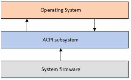
Fig. 1 Fig. i-1 - ACPI overview
ACPI defines two types of data structures that are shared between system firmware and the OS via the ACPI subsystem: data tables and definition blocks (see figure i-2). These data structures are the primary communication mechanism between the firmware and the OS. Data tables store raw data and are consumed by device drivers. Definition blocks consist of byte code that is executable by an interpreter.
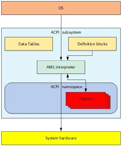
Fig. 2 Fig. i-2 - ACPI Structure
Upon initialization, the AML interpreter extracts byte code in the definition blocks as enumerable objects. This collection of enumerable objects forms an OS construct called the ACPI namespace. Objects in the ACPI namespace can either have a directly defined value, or be evaluated by the AML interpreter. The AML interpreter, directed by the OS, evaluates objects and then interfaces with system hardware to perform necessary operations.
The definition block byte code is compiled from the ACPI Source Language (ASL) code. ASL is the language used to define ACPI objects and to write control methods. An ASL compiler translates ASL into ACPI Machine Language (AML) byte code. AML is the language processed by the AML interpreter, as shown in figure i-3.
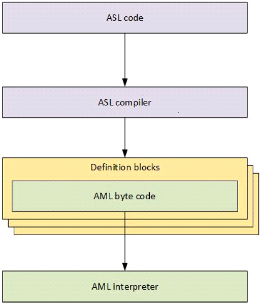
Fig. 3 Fig. i-3 - ASL and AML
ACPI Source Language (ASL) code is used to define objects and control methods. Then the ASL compiler translates ASL into ACPI Machine Language (AML) byte code contained within ACPI definition Blocks. Definition blocks consist of an identifying table header and byte code that is executable by an AML interpreter.
The AML interpreter executes byte code and evaluates objects in the definition blocks to allow the byte code to perform loop constructs, conditional evaluations, access defined address spaces, and perform other operations that applications require. The AML interpreter has read/write access to defined address spaces, including system memory, I/O, PCI configuration, and more. It accesses these address spaces by defining entry points called objects. Objects can either have a directly defined value or else must be evaluated and interpreted by the AML interpreter.
This collection of enumerable objects is an OS construct called the ACPI namespace. The namespace is a hierarchical representation of the ACPI devices on a system. The system bus is the root of enumeration for these ACPI devices. Devices that are enumerable on other buses, like PCI or USB devices, are usually not enumerated in the namespace. Instead, their own buses enumerate the devices and load their drivers. However, all enumerable buses have an encoding technique that allows ACPI to encode the bus-specific addresses of the devices so they can be found in ACPI, even though ACPI usually does not load drivers for these devices.
Generally, devices that have a _HID object (hardware identification object) are enumerated and have their drivers loaded by ACPI. Devices that have an _ADR object (physical address object) are usually not enumerated by ACPI and generally do not have their drivers loaded by ACPI. _ADR devices usually can perform all necessary functions without involving ACPI, but in cases where the device driver cannot perform a function, or if the driver needs to communicate to system firmware, ACPI can evaluate objects to perform the needed function.
As an example of this, PCI does not support native hotplug. However, PCI can use ACPI to evaluate objects and define methods that allow ACPI to fill in the functions necessary to perform hotplug on PCI.
An additional aspect of ACPI is a runtime model that handles any ACPI interrupt events that occur during system operation. ACPI continues to evaluate objects as necessary to handle these events. This interrupt-based runtime model is discussed in greater detail in the Runtime model section below.
ACPI Initialization
The best way to understand how ACPI works is chronologically. The moment the user powers up the system, the system firmware completes its setup, initialization, and self tests.
The system firmware then uses information obtained during firmware initialization to update the ACPI tables as necessary with various platform configurations and power interface data, before passing control to the bootstrap loader. The extended root system description table (XSDT) is the first table used by the ACPI subsystem and contains the addresses of most of the other ACPI tables on the system. The XSDT points to the fixed ACPI description table (FADT) as well as other major tables that the OS processes during initialization. After the OS initializes, the FADT directs the ACPI subsystem to the differentiated system description table (DSDT), which is the beginning of the namespace because it is the first table that contains a definition block.
The ACPI subsystem then processes the DSDT and begins building the namespace from the ACPI definition blocks. The XSDT also points to the secondary system description tables (SSDTs) and adds them to the namespace. The ACPI data tables give the OS raw data about the system hardware.
After the OS has built the namespace from the ACPI tables, it begins traversing the namespace and loading device drivers for all the _HID devices it encounters in the namespace. See figure i-4.
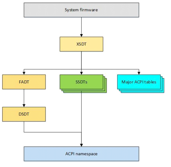
Fig. 4 Fig. i-4 ACPI Initialization
In the ACPI Intialization diagram above, system firmware updates the ACPI tables as necessary with information only available at runtime, before handing off control to the bootstrap loader. The XSDT is the first table used by the OS’s ACPI subsystem, and contains addresses of most other ACPI tables on the system. The XSDT points to the FADT, the SSDTs, and other major ACPI tables. The FADT directs the ACPI subsystem to the DSDT, which is the beginning of the namespace because DSDT is the first table that contains a definition block. The ACPI subsystem then consumes the DSDT and begins building the ACPI namespace from the definition blocks. The XSDT also points to the SSDTs and adds them to the namespace.
Runtime Model
After the system is up and running, ACPI works with the OS to handle any ACPI events that occur via an interrupt. This interrupt invokes ACPI events in one of two general ways: fixed events and general purpose events (GPEs).
Fixed events are ACPI events that have a predefined meaning in the ACPI specification. These fixed events include actions like pressing the power button or ACPI timer overflows. These events are handled directly by the OS handlers.
GPEs are ACPI events that are not predefined by the ACPI specification. These events are usually handled by evaluating control methods, which are objects in the namespace and can access system hardware. When the ACPI subsystem evaluates the control method with the AML interpreter, the GPE object handles the events according to the OS’s implementation. Typically this might involve issuing a notification to a device to invoke the device driver to perform a function.
We discuss a generic example of this runtime model in the next section.
Thermal Event Example
ACPI includes a thermal model to allow systems to control the system temperature either actively (by performing actions like turning a fan on) or passively by reducing the amount of power the system uses (by performing actions like throttling the processor). We can use an example of a generic thermal event shown in Figure i-5 to demonstrate how the ACPI runtime model works.
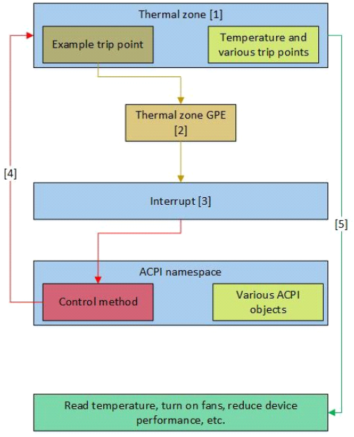
Fig. 5 Fig. i-5 Runtime Thermal Event
The ACPI thermal zone includes control methods to read the current system temperature and trip points.
When the OS initially finds a thermal zone in the namespace, it loads the thermal zone driver, which evaluates the thermal zone to obtain the current temperature and trip points.
When a system component heats up enough to trigger a trip point, a thermal zone GPE occurs.
The GPE causes an interrupt to occur. When the ACPI subsystem receives the interrupt, it first checks whether any fixed events have occurred. In this example, the thermal zone event is a GPE, so no fixed event has occurred.
The ACPI subsystem then searches the namespace for the control method that matches the GPE number of the interrupt. Upon finding it, the ACPI subsystem evaluates the control method, which might then access hardware and/or notify the thermal zone handler.
The operating system’s thermal zone handler then takes whatever actions are necessary to handle the event, including possibly accessing hardware.
ACPI is a very robust interface implementation. The thermal zone trip point could notify the system to turn on a fan, reduce a device’s performance, read the temperature, shut down the system, or any combination of these and other actions depending on the need.
This runtime model is used throughout the system to manage all of the ACPI events that occur during system operation.
Summary
ACPI can best be described as a framework of concepts and interfaces that are implemented to form a subsystem within the host OS. The ACPI tables, handlers, interpreter, namespace, events, and interrupt model together form this implementation of ACPI, creating the ACPI subsystem within the host OS. In this sense, ACPI is the interface between the system hardware/firmware and the OS and OS applications for configuration and power management. This gives various OS a standardized way to support power management and configuration via the ACPI namespace.
The ACPI namespace is the enumerable, hierarchical representation of all ACPI devices on the system and is used to both find and load drivers for ACPI devices on the system. The namespace can be dynamic by evaluating objects and sending interrupts in real time, all without the need for the OS to call native system firmware code. This enables device manufacturers to code their own instructions and events into devices. It also reduces incompatibility and instability by implementing a standardized power management interface.