18. SPI Protocol Stack
18.1. Design Discussion
The SPI protocol stack enables third party silicon vendors to write UEFI drivers for their products by decoupling the SPI chip details from the SPI controller and SPI bus configuration details.
18.1.1. SPI Bus Overview
Each peripheral on the SPI bus share the clock, data out and data in lines. The peripheral is addressed by using a unique chip select line. Communications with the peripheral must be done at or below the maximum clock rate which the peripheral supports and must use the proper clock polarity and phase.
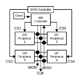
Fig. 18.1 SPI Bus
The SPI controller must contain the data shift register and clock gating logic which honors clock phase, clock polarity and only presents clock pulses when valid data is on the SPI bus. The SPI controller must pause the clock while waiting for more data.
Independent logic blocks may provide the clock frequency used by the SPI controller as well as the GPIOs used for the SPI chip selects.
18.1.2. SPI Protocol Stack Overview
The SPI driver stack is being split on functional lines. Most of the complexity ends up in the SPI bus layer, simplifying the SPI peripheral, SPI controller and board layers.
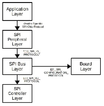
Fig. 18.2 SPI Layers
The SPI protocol layers are:
Application Layer - Applications using the SPI chips
SPI Peripheral Layer - Converts an SPI chip request into one or more transactions on the SPI bus
SPI Bus Layer - Handles:
SPI Peripheral Device Enumeration
SPI Transaction Management
SPI Controller Management
SPI Host Controller Layer - Handles details of the SPI controller
SPI Board Layer - Contains:
SPI bus descriptions
SPI part descriptions
Alternative SPI bus clock support
Alternative SPI chip select support
The SPI bus layer provides a data connection point with an EFI_SPI_IO_PROTOCOL data structure for each SPI peripheral. This data connection point exports the SpiPeripheralDriverGuid from the EFI_SPI_PART data structure. The SPI peripheral drivers connect to the connection points with the corresponding GUID.
An example:
A generic SPI flash driver is written and provides the GUID {5993c862-5c3f-4ae8-804d-8c89ad962c31} for use by SPI flash peripherals that meet the criteria specified by the developer of the SPI flash driver. The board developer chooses an SPI flash part, let’s say a WinBond W25Q64FV. Ideally the SPI chip vendor would provide a header file containing the EFI_SPI_PART definition. When that is not available, the board developer could create an EFI_SPI_PART data structure and fill it with data from the datasheet as follows:
CONST EFI_SPI_PART Winbond_W25Q64FV = {
  L"Winbond",
  L"W25Q64FV",
  0,
  MHz(104), // Page 75, 3.0V - 3.6V
  FALSE // Page 6, Section 3.1
};
When the SPI bus layer creates the EFI_SPI_IO_PROTOCOL data structure for this device, the generic SPI flash driver is able to find and connect to it by calling OpenProtocol with the GUID specified above.
Some SPI chip examples:
Maxim MAX3111E - UART and RS232 transceiver
Maxim MAX6950 - Seven segment numeric LED controller
Serial SPI NOR flash, one of:
Atmel AT25DF321 - 4 MiB SPI NOR flash
Winbond W2SQ80DV - 1 MiB SPI NOR flash
Winbond W25Q16DV - 2 MiB SPI NOR flash
Winbond W25Q32FV - 4 MiB SPI NOR flash
Winbond W25Q64FV - 8 MiB SPI NOR flash
Spansion S25FL164K - 16 MiB SPI NOR flash
Micron N2SQ128A - 32 MiB SPI NOR flash
Winbond W2SQ128FV - 32 MiB SPI NOR flash
The board vendor may provide example code which describes the SPI buses and SPI peripherals to simplify the configuration process. The example code may be modified by the board consumer to adjust for added SPI devices or SPI buses.
18.1.3. Application Layer
The application layer interacts with various chip specific drivers using vendor specific protocols. Example applications are:
A background application which reads gets the system time once per second and uses the MAX6950 driver to display the time on a four seven-segment displays.
A background application which uses the Texas Instruments ADC108S102 driver to read a 10-bit voltage value from the analog-to-digital converter and displays the result on seven-segment displays driven by the MAX6950.
18.1.4. SPI Peripheral Layer
This layer provides vendor specific interfaces to the SPI chips. The upper interface to the SPI peripheral layer is chip specific and determined by the UEFI or Pl specifications where there is a standard or by the chip vendor when a standard does not exist.
The lower interface of the SPI peripheral layer connects to one or more of the SPI peripherals exposed by the SPI bus layer as an EFI_SPI_IO_PROTOCOL instance. The SPI peripheral driver interacts with the SPI chip by issuing data transactions to the SPI bus layer. These transactions make their way to the SPI controller layer where they are placed onto the SPI bus and data is exchanged with the SPI chip.
18.1.5. SPI I/O Interface
The SPI bus layer creates an EFI_SPI_IO_PROTOCOL instance for each SPI chip listed in the board layer. However unlike other protocols, the EFI_SPI_IO_PROTOCOL instance is identified by a GUID that is unique to the SPI chip driver to which it should connect. This differs from other bus protocols which produce a bus-specific GUID.
The rational behind this is decision is based upon:
No common device support
Performance and code size
SPI device enumeration performed infrequently
18.1.5.1. No Common Device Support
With other protocols such as PCI and USB, even though the devices differ, there is a common hardware support layer for peripheral identity, resource allocation and attaching the device to the bus. SPI chips differ in this respect because there are no hardware standards! Bus attachment is done by the board developer at a hardware level. From a software viewpoint as soon as chip select is asserted, the SPI chip is on the bus. Also with SPI there are no common commands that may be issued to identify or enable the chip. As such there is no advantage exposing the EFI_SPI_IO_PROTOCOL with a generic GUID.
18.1.5.2. Performance and Code Size
Times have changed since UEFI was originally architected and implemented. In todays world, the firmware engineers are being asked for sub-one-second boot times and a smaller firmware footprint with more functionality. Using a generic GUID for the EFI_SPI_IO_PROTOCOL requires that each SPI peripheral driver implement more code to verify some other identifier to determine if the driver should use this device. This additional check adds cost and complexity to the SPI peripheral driver. The costs are the development time to implement and debug the code as well as the CPU time to execute the code. This code also has a multiplicative effect on the firmware footprint.
18.1.5.3. SPI Device Enumeration Performed Infrequently
The claim is that SPI device enumeration will be performed infrequently.
How often is SPI device enumeration a necessary operation?
Is it a requirement that this operation be done using a generic GUID for EFI_SPI_IO_PROTOCOL ?
What are the use cases for this operation?
Eliminating the generic GUID for EFI_SPI_IO_PROTOCOL removes one way of doing SPI device enumeration. However SPI device enumeration is still possible.
SPI device enumeration is easiest done using the EFI_SPI_CONFIGURATION_PROTOCOL . From this protocol is possible to determine the SPI buses in the system and the devices which are attached to these buses. With a little extra work, calling LocateHandleBuffer it is possible to identify the handles which use the SPI driver GUID and match the EFI_SPI_IO_PROTOCOL interface.
Device paths may also be used to find handles which are attached to a specific SPI host controller. Each SPI peripheral attaches a HW_CONTROLLER node to the device path.
18.1.5.4. Synchronous Operation
All SPI I/O layer transactions are synchronous. No support is provided for asynchronous transactions.
18.1.5.5. SPI Transaction Management
The SPI I/O layer allocates a EFI_SPI_BUS_TRANSACTION data structure which contains the parameters that will be passed to the SPI host controller as part of this SPI transaction. The SPI bus layer uses this structure to control and complete the SPI transaction.
Synchronizing with the SPI bus layer schedules the SPI transaction on a free SPI host controller.
18.1.6. SPI Bus Layer
The SPI bus layer manages the SPI transactions for each of the host’s SPI controllers. SPI peripheral drivers submit SPI transactions to the SPI bus layer which in turn submits them to the host’s SPI controller.
The SPI transaction consists of:
Adjusting the clock speed, polarity and phase for an SPI peripheral
Use the chip select to enable the SPI peripheral, signaling the transaction start to the chip
Transfer the data in one or both directions simultaneously
Remove the chip select from the SPI peripheral signaling the transaction end to the chip
Optionally, shutdown the SPI controller’s internal clock to reduce power
The SPI bus layer is responsible setting up the SPI clock and chip select. This ensures that the chip set up is done properly across all SPI controller drivers. The SPI bus layer uses the SPI chip data from the board layer to determine the clock phase and polarity. The clock frequency is the lowest frequency specified by:
Maximum SPI controller clock frequency
Supported SPI controller clock frequency < = SPI chip maximum clock frequency
Supported SPI controller clock frequency < = non-zero ClockHz
After setting up the clock, the SPI bus layer asserts the appropriate chip select and then passes the SPI transaction to the SPI controller to start the data flow in both directions. Upon completion, the SPI bus layer deasserts the chip select and completes the SPI transaction to the SPI peripheral layer.
18.1.6.1. Half Duplex SPI controllers
Various SPI controllers support a half-duplex operation in addition to the full-duplex operation. The benefits of the half-duplex operation on the system are that less physical memory tied up during the operation and the memory bandwidth is cut in half for the operation.
It is beneficial to the system for the SPI architecture to support the half duplex operations of the SPI controller. Additionally it reduces code size and memory footprint by eliminating unnecessary buffers in the SPI peripheral drivers when half-duplex operations are performed on the SPI chip.
Write Then Read Operations
SPI flash chips and some SPI UARTs support write then read operations using SPI. The NXP SC16IS750/760 is an example of a UART designed for I2C and SPI which performs half-duplex operations which are a mix of transmit and receive.
SPI NOR flash chips such as the Winbond W25Q64FV also perform half-duplex operations which are a mix of transmit and receive. These operation consist of writing a command byte and possibly an address and then immediately reading data either from the status register or memory.
SPI Controller Support
Since SPI is inherently full-duplex, the SPI host controller should support full-duplex operation. Not all SPI controllers however are able to support half-duplex or write-then-read operation. In this case, the SPI bus layer converts the SPI transaction into a full-duplex transaction by allocating the necessary buffers and if necessary coping any write data into the new buffer. The SPI bus layer then hands the full-duplex transaction to the SPI host controller for processing. Upon completion, the SPI bus driver copies any necessary data from the full-duplex buffers into the SPI peripheral layer’s receive buffer and then frees the allocated full-duplex buffers. This conversion allows the SPI peripheral drivers to choose transaction types which optimize system resources and performance in the general case.
SPI Controller To SPI Bus Connection
For DXE, the SPI host controller is identified by the device path. The SPI board layer includes copy of this device path in the ControllerPath field of the EFI_SPI_BUS structure. When the DXE version of the SPI bus layer locates an SPI host controller, the SPI bus layer matches the device path for the SPI host controller to the device field in the ControllerPath of the EFI_SPI_BUS structure in the board layer. Once this connection is made, the SPI bus layer can create the necessary SPI I/O interfaces.
18.1.7. SPI Host Controller Layer
The SPI host controller layer provides a simple interface to the SPI controller. This layer only handles SPI controller details for a single transaction.
The support at this layer is broken into three primary routines:
Clock set up
Chip selection
Data movement
The SPI bus layer calls these routines to initiate and complete the SPI transaction.
18.1.7.1. Legacy SPI Flash Controller
The legacy SPI flash controller is designed to handle SPI NOR flash devices. This controller has several limitations and several security enhancements that impact the design of the SPI bus I/O layers and the SPI NOR flash peripheral driver. The security enhancements include:
BIOS base address
Protect range registers
Controller configuration lock
Prefix type table
Opcode menu table
Opcode type table
BIOS base address
Protect range registers
The security enhancements are handled by the EFI_LEGACY_SPI_CONTROLLER_PROTOCOL . This protocol provides the functions support the security features of the legacy SPI flash controller as well as functions to work around the flash targeted design of the controller.
The limitations of the legacy SPI flash controller include:
8-bit frames only
Fixed clock rate
No full-duplex transaction support
No read-only transaction support
Reads: 64-byte maximum transfer length
Writes: 67-byte maximum transfer length
Prefix opcode table
Opcode menu table
These limitations are handled by:
Setting frame size support to 8-bit only
Using the legacy SPI flash controller’s clock routine to validate the requested clock frequency
Letting the legacy SPI flash controller’s transaction routine fail the full-duplex and read-only transactions
Setting the maximum transfer size to 64 bytes
Adding a couple of flags to indicate that the opcode and 3 address bytes are included in the maximum transfer size
Using the EFI_LEGACY_SPI_CONTROLLER_PROTOCOL to set the erase block opcode
Using the EFI_LEGACY_SPI_CONTROLLER_PROTOCOL to set the write status prefix opcode
18.2. DXE Code Definitions
The SPI protocol stack consists of the following protocols:
EFI_LEGACY_SPI_FLASH_PROTOCOL - The upper layers use this protocol to access the BIOS space address and protection registers of the legacy SPI flash controller.
EFI_SPI_NOR_FLASH_PROTOCOL - The upper layers use this protocol to interact with SPI NOR flash devices.
EFI_SPI_IO_PROTOCOL - The SPI peripheral drivers use this to interact with chips on the SPI bus.
EFI_SPI_HC_PROTOCOL - The SPI bus layer uses this to interact with the host’s SPI controller.
EFI_LEGACY_SPI_CONTROLLER_PROTOCOL - The flash layer uses this protocol to invoke the additional functions provided by the legacy SPI controller.
EFI_SPI_CONFIGURATION_PROTOCOL - The SPI bus layer uses this to interact with the board layer database and additional logic blocks for clock and GPIO controllers.
18.2.1. EFI_SPI_CONFIGURATION_PROTOCOL
Summary
Describe the details of the board’s SPI buses to the SPI driver stack.
GUID
// {85a6d3e6-b65b-4afc-b38f-c6d54af6ddc8}
#define EFI_SPI_CONFIGURATION_GUID \
{ 0x85a6d3e6, 0xb65b, 0x4afc, { 0xb3, 0x8f, 0xc6, 0xd5, \
0x4a, 0xf6, 0xdd, 0xc8 }}
Protocol Interface Structure
typedef struct _EFI_SPI_CONFIGURATION_PROTOCOL {
  UINT32 BusCount;
  CONST EFI_SPI_BUS *CONST *CONST Buslist;
} EFI_SPI_CONFIGURATION_PROTOCOL;
Parameters
- BusCount
The number of SPI buses on the board.
- Buslist
The address of an array of EFI_SPI_BUS data structure addresses.
Description
The board layer uses the EFI_SPI_CONFIGURATION_PROTOCOL to expose the data tables which describe the board’s SPI buses. The SPI bus layer uses these tables to configure the clock and chip select, and manage the SPI transactions on the SPI controllers.
The configuration tables describe:
The number of SPI buses on the board
Which SPI chips are connected to each SPI bus
For each SPI chip the configuration describes:
The maximum clock frequency for the SPI part
The clock polarity needed for the SPI part
Whether the SPI controller uses a separate clock generator that needs to be set up
The chip select polarity
Whether the SPI controller or a GPIO pin is used for the chip select
The data sampling edge for the SPI part.
The EFI_SPI_PERIPHERAL and EFI_SPI_BUS data structures are defined later in this section.
18.2.2. EFI_SPI_CHIP_SELECT
Summary
Manipulate the chip select for an SPI device.
Prototype
typedef
EFI_STATUS
(EFIAPI *EFI_SPI_CHIP_SELECT) (
  IN CONST EFI_SPI_PERIPHERAL *SpiPeripheral,
  IN BOOLEAN PinValue
  );
Parameters
- SpiPeripheral
The address of an EFI_SPI_PERIPHERAL data structure describing the SPI peripheral whose chip select pin is to be manipulated. The routine may access the ChipSelectParameter field to gain sufficient context to complete the operation.
- PinValue
The value to be applied to the chip select line of the SPI peripheral.
Description
This routine must be called at or below TPL_NOTIFY . Update the value of the chip select line for an SPI peripheral. The SPI bus layer calls this routine either in the board layer or in the SPI controller to manipulate the chip select pin at the start and end of an SPI transaction.
Status Codes Returned
EFI_SUCCESS |
The chip select was set successfully |
EFI_NOT_READY |
Support for the chip select is not properly initialized |
EFI_INVALID_PARAMETER |
The SpiPeripheral ChipSelectParameter value is invalid |
18.2.3. EFI_SPI_PART
Summary
Describe the properties of an SPI chip.
Prototype
typedef struct _EFI_SPI_PART
{
  CONST CHAR16 *Vendor;
  CONST CHAR16 *PartNumber;
  UINT32 MinClockHz;
  UINT32 MaxClockHz;
  BOOLEAN ChipSelectPolarity;
} EFI_SPI_PART;
Parameters
- Vendor
A Unicode string specifying the SPI chip vendor.
- PartNumber
A Unicode string specifying the SPI chip part number.
- MinClockHz
The minimum SPI bus clock frequency used to access this chip. This value may be specified in the chip’s datasheet. If not, use the value of zero.
- MaxClockHz
The maximum SPI bus clock frequency used to access this chip. This value is found in the chip’s datasheet.
- ChipSelectPolarity
Specify the polarity of the chip select pin. This value can be found in the SPI chip’s datasheet. Specify TRUE when a one asserts the chip select and FALSE when a zero asserts the chip select.
Description
The EFI_SPI_PART data structure provides a description of an SPI part which is independent of the use on the board. This data is available directly from the part’s datasheet and may be provided by the vendor.
18.2.4. EFI_SPI_PERIPHERAL
Summary
Describe the board specific properties associated with a specific SPI chip.
Prototype
typedef struct _EFI_SPI_PERIPHERAL
{
  CONST EFI_SPI_PERIPHERAL *NextSpiPeripheral;
  CONST CHAR16 *FriendlyName;
  CONST GUID *SpiPeripheralDriverGuid;
  CONST EFI_SPI_PART *SpiPart;
  UINT32 MaxClockHz;
  BOOLEAN ClockPolarity;
  BOOLEAN ClockPhase;
  UINT32 Attributes;
  CONST VOID *ConfigurationData;
  CONST EFI_SPI_BUS *SpiBus;
  EFI_SPI_CHIP_SELECT ChipSelect;
  VOID *ChipSelectParameter;
} EFI_SPI_PERIPHERAL;
Parameters
- NextSpiPeripheral
Address of the next EFI_SPI_PERIPHERAL data structure. Specify NULL if the current data structure is the last one on the SPI bus.
- FriendlyName
A unicode string describing the function of the SPI part.
- SpiPeripheralDriverGuid
Address of a GUID provided by the vendor of the SPI peripheral driver. Instead of using a ” EFI_SPI_IO_PROTOCOL ” GUID, the SPI bus driver uses this GUID to identify an EFI_SPI_IO_PROTOCOL data structure and to provide the connection points for the SPI peripheral drivers. This reduces the comparison logic in the SPI peripheral EFI_DRIVER_BINDING_PROTOCOL.Supported() routine.
- SpiPart
The address of an EFI_SPI_PART data structure which describes this chip.
- MaxClockHz
The maximum clock frequency is specified in the EFI_SPI_PART . When this value is non-zero and less than the value in the EFI_SPI_PART then this value is used for the maximum clock frequency for the SPI part.
- ClockPolarity
Specify the idle value of the clock as found in the datasheet. Use zero (0) if the clock’s idle value is low or one (1) if the clock’s idle value is high.
- ClockPhase
Specify the clock delay after chip select. Specify zero (0) to delay an entire clock cycle or one (1) to delay only half a clock cycle.
- Attributes
SPI peripheral attributes, select zero or more of:
SPI_PART_SUPPORTS_2_BIT_DATA_BUS_WIDTH - The SPI peripheral is wired to support a two-bit data bus
SPI_PART_SUPPORTS_4_BIT_DATA_BUS_WIDTH - The SPI peripheral is wired to support a four-bit data bus
- ConfigurationData
Address of a vendor specific data structure containing additional board configuration details related to the SPI chip. The SPI peripheral layer uses this data structure when configuring the chip.
- SpiBus
The address of an EFI_SPI_BUS data structure which describes the SPI bus to which this chip is connected.
- ChipSelect
Address of the routine which controls the chip select pin for this SPI peripheral. Call the SPI host controller’s chip select routine when this value is set to NULL .
- ChipSelectParameter
Address of a data structure containing the additional values which describe the necessary control for the chip select. When ChipSelect is NULL , the declaration for this data structure is provided by the vendor of the host’s SPI controller driver. The vendor’s documentation specifies the necessary values to use for the chip select pin selection and control.
When Chipselect is not NULL , the declaration for this data structure is provided by the board layer.
Description
The EFI_SPI_PERIPHERAL data structure describes how a specific block of logic which is connected to the SPI bus. This data structure also selects which upper level driver is used to manipulate this SPI device. The SpiPeripheraLDriverGuid is available from the vendor of the SPI peripheral driver.
18.2.5. EFI_SPI_CLOCK
Summary
Set up the clock generator to produce the correct clock frequency, phase, and polarity for an SPI chip.
Prototype
typedef
EFI_STATUS
(EFIAPI *EFI_SPI_CLOCK) (
  IN CONST EFI_SPI_PERIPHERAL *SpiPeripheral,
  IN UINT32 *ClockHz
  );
Parameters
- SpiPeripheral
Pointer to a EFI_SPI_PERIPHERAL data structure from which the routine can access the ClockParameter , ClockPhase, and ClockPolarity fields. The routine also has access to the names for the SPI bus and chip which can be used during debugging.
- ClockHz
Pointer to the requested clock frequency. The clock generator will choose a supported clock frequency which is less then or equal to this value. Specify zero to turn the clock generator off. The actual clock frequency supported by the clock generator will be returned.
Description
This routine must be called at or below TPL_NOTIFY .
This routine updates the clock generator to generate the correct frequency and polarity for the SPI clock.
Status Codes Returned
EFI_SUCCESS |
The clock was set up successfully |
EFI_UNSUPPORTED |
The SPI controller was not able to support the frequency requested by ClockHz |
18.2.6. EFI_SPI_BUS
Summary
Describe the board specific details associated with an SPI bus.
Prototype
typedef struct _EFI_SPI_BUS {
  CONST CHAR16 *FriendlyName;
  CONST EFI_SPI_PERIPHERAL *Peripherallist;
  CONST EFI_DEVICE_PATH_PROTOCOL *ControllerPath;
  EFI_SPI_CLOCK Clock;
  VOID *ClockParameter;
} EFI_SPI_BUS;
Parameters
- FriendlyName
A Unicode string describing the SPI bus
- Peripheral List
Address of the first EFI_SPI_PERIPHERAL data structure connected to this bus. Specify NULL if there are no SPI peripherals connected to this bus.
- ControllerPath
Address of an EFI_DEVICE_PATH_PROTOCOL data structure which uniquely describes the SPI controller.
- Clock
Address of the routine which controls the clock used by the SPI bus for this SPI peripheral. The SPI host controller’s clock routine is called when this value is set to NULL.
- ClockParameter
Address of a data structure containing the additional values which describe the necessary control for the clock. When Clock is NULL , the declaration for this data structure is provided by the vendor of the host’s SPI controller driver. When Clock is not NULL , the declaration for this data structure is provided by the board layer.
Description
The EFI_SPI_BUS data structure provides the connection details between the physical SPI bus and the EFI_SPI_HC_PROTOCOL instance which controls that SPI bus. This data structure also describes the details of how the clock is generated for that SPI bus. Finally this data structure provides the list of physical SPI devices which are attached to the SPI bus.
Summary
Macros to easily specify frequencies in hertz, kilohertz and megahertz.
Prototype
#define Hz(Frequency)    (Frequency)
#define KHz(Frequency)   (1000 * Hz(Frequency))
#define MHz(Frequency)   (1000 * KHz(Frequency))
18.2.7. EFI_SPI_NOR_FLASH_PROTOCOL
Summary
The EFI_SPI_NOR_FLASH_PROTOCOL exists in the SPI peripheral layer. This protocol manipulates the SPI NOR flash parts using a common set of commands. The board layer provides the interconnection and configuration details for the SPI NOR flash part. The SPI NOR flash driver uses this configuration data to expose a generic interface which provides the following APls:
Read manufacture and device ID
Read data
Read data using low frequency
Read status
Write data
Erase 4 KiB blocks
Erase 32 or 64 KiB blocks
Write status
The EFI_SPI_NOR_FLASH_PROTOCOL also exposes some APls to set the security features on the legacy SPI flash controller.
GUID
// {b57ec3fe-f833-4ba6-8578-2a7d6a87444b}
#define EFI_SPI_NOR_FLASH_PROTOCOL_GUID \
{ 0xb57ec3fe, 0xf833, 0x4ba6, { 0x85, 0x78, 0x2a, 0x7d, \
 0x6a, 0x87, 0x44, 0x4b }}
Protocol Interface Structure
struct _EFI_SPI_NOR_FLASH_PROTOCOL {
  CONST EFI_SPI_PERIPHERAL \*SpiPeripheral;
  UINT32 FlashSize;
  UINT8 DeviceId [3];
  UINT32 EraseBlockBytes;
  EFI_SPI_NOR_FLASH_PROTOCOL_GET_FLASH_ID GetFlashId;
  EFI_SPI_NOR_FLASH_PROTOCOL_READ_DATA ReadData;
  EFI_SPI_NOR_FLASH_PROTOCOL_READ_DATA LfReadData;
  EFI_SPI_NOR_FLASH_PROTOCOL_READ_STATUS ReadStatus;
  EFI_SPI_NOR_FLASH_PROTOCOL_WRITE_STATUS WriteStatus;
  EFI_SPI_NOR_FLASH_PROTOCOL_WRITE_DATA WriteData;
  EFI_SPI_NOR_FLASH_PROTOCOL_ERASE Erase;
};
Parameters
- SpiPeripheral
Pointer to an EFI_SPI_PERIPHERAL data structure
- FlashSize
Flash size in bytes
- DeviceId
Manufacturer and Device ID
- EraseBlockBytes
Erase block size in bytes
18.2.8. SPI Flash Driver GUID
Use a pointer to gEfiSpiNorFlashDriverGuid in the EFI_SPI_PERIPHERAL structure to connect an SPI NOR flash part to the SPI flash driver.
18.2.9. EFI_SPI_NOR_FLASH_PROTOCOL.GetFlashld()
Summary
Read the 3 byte manufacture and device ID from the SPI flash.
Prototype
typedef
EFI_STATUS
(EFIAPI *EFI_SPI_NOR_FLASH_PROTOCOL_GET_FLASH_ID) (
  IN CONST EFI_SPI_NOR_FLASH_PROTOCOL *This,
  OUT UINT8 *Buffer
  );
Parameters
- This
Pointer to an EFI_SPI_NOR_FLASH_PROTOCOL data structure.
- Buffer
Pointer to a 3 byte buffer to receive the manufacturer and device ID.
Description
This routine must be called at or below TPL_NOTIFY .
This routine reads the 3 byte manufacture and device ID from the flash part filling the buffer provided.
Status Codes Returned
EFI_SUCCESS |
The manufacture and device ID was read successfully |
EFI_INVALID_PARAMETER |
Buffer is NULL |
EFI_DEVICE_ERROR |
Invalid data received from SPI flash part |
18.2.10. EFI_SPI_NOR_FLASH_PROTOCOL.ReadData()
Summary
Read data from the SPI flash.
Prototype
typedef
EFI_STATUS
(EFIAPI \*EFI_SPI_NOR_FLASH_PROTOCOL_READ_DATA) (
  IN CONST EFI_SPI_NOR_FLASH_PROTOCOL  *This,
  IN UINT32                            FlashAddress,
  IN UINT32 LengthInBytes, OUT UINT8   *Buffer
  );
Parameters
- This
Pointer to an EFI_SPI_NOR_FLASH_PROTOCOL data structure.
- FlashAddress
Address in the flash to start reading
- LengthInBytes
Read length in bytes
- Buffer
Address of a buffer to receive the data
Description
This routine must be called at or below TPL_NOTIFY .
This routine reads data from the SPI part in the buffer provided.
Status Codes Returned
EFI_SUCCESS |
The data was read successfully. |
EFI_INVALID_PARAMETER |
Buffer is NULL |
EFI_INVALID_PARAMETER |
FlashAddress >= This->FlashSize |
EFI_INVALID_PARAMETER |
LengthInBytes > This->FlashSize - FlashAddress |
18.2.11. EFI_SPI_NOR_FLASH_PROTOCOL.LfReadData()
Summary
Low frequency read data from the SPI flash.
Prototype
typedef
EFI_STATUS
(EFIAPI *EFI_SPI_NOR_FLASH_PROTOCOL_READ_DATA) (
  IN CONST EFI_SPI_NOR_FLASH_PROTOCOL *This,
  IN UINT32 FlashAddress,
  IN UINT32 LengthInBytes,
  OUT UINTS *Buffer
  );
Parameters
- This
Pointer to an EFI_SPI_NOR_FLASH_PROTOCOL data structure.
- FlashAddress
Address in the flash to start reading
- LengthInBytes
Read length in bytes
- Buffer
Address of a buffer to receive the data
Description
This routine must be called at or below TPL_NOTIFY .
This routine reads data from the SPI part in the buffer provided.
Status Codes Returned
EFI_SUCCESS |
The data was read successfully. |
EFI_INVALID_PARAMETER |
Buffer is NULL |
EFI_INVALID_PARAMETER |
FlashAddress >= This->FlashSize |
EFI_INVALID_PARAMETER |
LengthInBytes > This->FlashSize - FlashAddress |
18.2.12. EFIEFI_SPI_NOR_FLASH_PROTOCOL.ReadStatus()
Summary
Read the flash status register.
Prototype
typedef
EFI STATUS
(EFIAPI *EFI_SPI_NOR_FLASH_PROTOCOL_READ_STATUS) (
  IN CONST EFI_SPI_NOR_FLASH_PROTOCOL *This,
  IN UINT32 LengthInBytes,
  OUT UINT8 *FlashStatus
  );
Parameters
- This
Pointer to an EFI_SPI_NOR_FLASH_PROTOCOL data structure.
- LengthInBytes
Number of status bytes to read.
- FlashStatus
Pointer to a buffer to receive the flash status.
Description
This routine must be called at or below TPL_NOTIFY . This routine reads the flash part status register.
Status Codes Returned
EFI_SUCCESS |
The status register was read successfully. |
18.2.13. EFI_SPI_NOR_FLASH_PROTOCOL.WriteStatus()
Summary
Write the flash status register.
Prototype
typedef
EFI_STATUS
(EFIAPI \*EFI_SPI_NOR_FLASH_PROTOCOL_WRITE_STATUS) (
  IN CONST EFI_SPI_NOR_FLASH_PROTOCOL *This,
  IN UINT32 LengthInBytes,
  IN UINT8 *FlashStatus
  );
Parameters
- This
Pointer to an EFI_SPI_NOR_FLASH_PROTOCOL data structure.
- LengthInBytes
Number of status bytes to write.
- FlashStatus
Pointer to a buffer containing the new status.
Description
This routine must be called at or below TPL_NOTIFY . This routine writes the flash part status register.
Status Codes Returned
EFI_SUCCESS |
The status write was successful. |
EFI_OUT_OF_RESOURCES |
Failed to allocate the write buffer. |
18.2.14. EFI_SPI_NOR_FLASH_PROTOCOL.WriteData()
Summary
Write data to the SPI flash.
Prototype
typedef
EFI_STATUS
(EFIAPI \*EFI_SPI_NOR_FLASH_PROTOCOL_WRITE_DATA) (
  IN CONST EFI_SPI_NOR_FLASH_PROTOCOL *This,
  IN UINT32 FlashAddress,
  IN UINT32 LengthInBytes,
  IN UINT8 *Buffer
  );
Parameters
- This
Pointer to an EFI_SPI_NOR_FLASH_PROTOCOL data structure.
- FlashAddress
Address in the flash to start writing
- LengthInBytes
Write length in bytes
- Buffer
Address of a buffer containing the data
Description
This routine must be called at or below TPL_NOTIFY .
This routine breaks up the write operation as necessary to write the data to the SPI part.
Status Codes Returned
EFI_SUCCESS |
The data was written successfully. |
EFI_INVALID_PARAMETER |
Buffer is NULL |
EFI_INVALID_PARAMETER |
FlashAddress >= This->FlashSize |
EFI_INVALID_PARAMETER |
LengthInBytes > This->FlashSize - FlashAddress |
EFI_OUT_OF_RESOURCES |
Insufficient memory to copy buffer. |
18.2.15. EFI_SPI_NOR_FLASH_PROTOCOL.Erase()
Summary
Efficiently erases one or more 4KiB regions in the SPI flash.
Prototype
typedef
EFI_STATUS
(EFIAPI *EFI_SPI_NOR_FLASH_PROTOCOL_ERASE) (
  IN CONST EFI_SPI_NOR_FLASH_PROTOCOL *This,
  IN UINT32 FlashAddress,
  IN UINT32 BlockCount
  );
Parameters
This
Pointer to an EFI_SPI_NOR_FLASH_PROTOCOL data structure
- FlashAddress
Address within a 4 KiB block to start erasing
- BlockCount
Number of 4 KiB blocks to erase
Description
This routine must be called at or below TPL_NOTIFY .
This routine uses a combination of 4 KiB and larger blocks to erase the specified area.
Status Codes Returned
EFI_SUCCESS |
The erase was completed successfully |
EFI_INVALID_PARAMETER |
FlashAddress This FlashSize |
EFI_INVALID_PARAMETER |
BlockCount 4 KiB This FlashSize FlashAddress |
18.2.16. EFI_LEGACY_SPI_FLASH_PROTOCOL
Summary
The EFI_LEGACY _SPI_FLASH_PROTOCOL extends the EFI_SPI_NOR_FLASH_PROTOCOL with APls to support the legacy SPI flash controller.
GUID
// {f01bed57-04bc-4f3f-9660-d6f2ea228259}
#define EFI_LEGACY_SPI_FLASH_PROTOCOL_GUID \
{ 0xf01bed57, 0x04bc, 0x4f3f, { 0x96, 0x60, 0xd6, 0xf2, \
  0xea, 0x22, 0x82, 0x59 }}
Protocol Interface Structure
struct _EFI_LEGACY_SPI_FLASH_PROTOCOL {
  EFI_SPI_NOR_FLASH_PROTOCOL FlashProtocol;
  ///
  /// Legacy flash (SP! host) controller support
  ///
  EFI_LEGACY_SPI_FLASH_PROTOCOL_BIOS_BASE_ADDRESS  BiosBaseAddress;
  EFI_LEGACY_SPI_FLASH_PROTOCOL_CLEAR_SPI_PROTECT  ClearSpiProtect;
  EFI_LEGACY_SPI_FLASH_PROTOCOL_IS_RANGE_PROTECTED IsRangeProtected;
  EFI_LEGACY_SPI_FLASH_PROTOCOL_PROTECT_NEXT_RANGE ProtectNextRange;
  EFI_LEGACY_SPI_FLASH_PROTOCOL_LOCK_CONTROLLER    LockController;
};
18.2.17. EFI_LEGACY _SPI_FLASH_PROTOCOL.BiosBaseAddress()
Summary
Set the BIOS base address.
Prototype
typedef
EFI_STATUS
(EFIAPI *EFI_LEGACY_SPI_FLASH_PROTOCOL_BIOS_BASE_ADDRESS) (
  IN CONST EFI_LEGACY_SPI_FLASH_PROTOCOL *This,
  IN UINT32 BiosBaseAddress
  );
Parameters
- This
Pointer to an EFI_LEGACY_SPI_FLASH_PROTOCOL data structure.
- BiosBaseAddress
The BIOS base address.
Description
This routine must be called at or below TPL_NOTIFY .
The BIOS base address works with the protect range registers to protect portions of the SPI NOR flash from erase and write operations . The BIOS calls this API prior to passing control to the OS loader.
Status Codes Returned
EFI_SUCCESS |
The BIOS base address was properly set |
EFI_ACCESS_ERROR |
The SPI controller is locked |
EFI_INVALID_PARAMETER |
The BIOS base address was already set |
EFI_UNSUPPORTED |
The BIOS base address was already set |
EFI_UNSUPPORTED |
Not a legacy SPI host controller |
18.2.18. EFI_LEGACY _SPI_FLASH_PROTOCOL.ClearSpiProtect()
Summary
Clear the SPI protect range registers.
Prototype
typedef
EFI_STATUS
(EFIAPI *EFI_LEGACY_SPI_FLASH_PROTOCOL_CLEAR_SPI_PROTECT) (
  IN CONST EFI_LEGACY_SPI_FLASH_PROTOCOL *This
  );
Parameters
- This
Pointer to an EFI_LEGACY_SPI_FLASH_PROTOCOL data structure.
Description
This routine must be called at or below TPL_NOTIFY .
The BIOS uses this routine to set an initial condition on the SPI protect range registers.
Status Codes Returned
EFI_SUCCESS |
The registers were successfully cleared |
EFI_ACCESS_ERROR |
The SPI controller is locked |
EFI_UNSUPPORTED |
Not a legacy SPI host controller |
18.2.19. EFI_LEGACY _SPI_FLASH_PROTOCOL.lsRangeProtected()
Summary
Determine if the SPI range is protected.
Prototype
typedef
BOOLEAN
(EFIAPI *EFI_LEGACY_SPI_FLASH_PROTOCOL_IS_RANGE_PROTECTED) (
  IN CONST EFI_LEGACY_SPI_FLASH_PROTOCOL *This,
  IN UINT32 BiosAddress,
  IN UINT32 BlocksToProtect
  );
Parameters
- This
Pointer to an EFI_LEGACY_SPI_FLASH_PROTOCOL data structure.
- BiosAddress
Address within a 4 KiB block to start protecting.
- BlocksToProtect
The number of 4 KiB blocks to protect.
Description
This routine must be called at or below TPL_NOTIFY .
The BIOS uses this routine to verify a range in the SPI is protected.
Return Value
TRUE |
The range is protected |
FALSE |
The range is not protected |
18.2.20. EFI_LEGACY_SPI_FLASH_PROTOCOL.ProtectNextRange()
Summary
Set the next protect range register.
Prototype
typedef
EFI_STATUS
(EFIAPI *EFI_LEGACY_SPI_FLASH_PROTOCOL_PROTECT_NEXT_RANGE) (
  IN CONST EFI_LEGACY_SPI_FLASH_PROTOCOL *This,
  IN UINT32 BiosAddress,
  IN UINT32 BlocksToProtect
  );
Parameters
- This
Pointer to an EFI_LEGACY_SPI_FLASH_PROTOCOL data structure.
- BiosAddress
Address within a 4 KiB block to start protecting.
- BlocksToProtect
The number of 4 KiB blocks to protect.
Description
This routine must be called at or below TPL_NOTIFY .
The BIOS sets the protect range register to prevent write and erase operations to a portion of the SPI NOR flash device.
Status Codes Returned
EFI_SUCCESS |
The register was successfullyupdated |
EFI_ACCESS_ERROR |
The SPI controller is locked |
EFI_INVALID_PARAMETER |
BiosAddress <This->BiosBaseAddress |
EFI_INVALID_PARAMETER |
BlocksToProtect * 4 KiB >This->MaximumRangeBytes |
EFI_INVALID_PARAMETER |
BiosAddress -This->BiosBaseAddress +(BlocksToProtect *4 KiB) > This->MaximumRangeBytes |
EFI_OUT_OF_RESOURCES |
No protect range registeravailable |
EFI_UNSUPPORTED |
Call This -> SetBaseAddress because the BIOS base address is not set |
EFI_UNSUPPORTED |
Not a legacy SPI host controller |
18.2.21. EFI_LEGACY _SPI_FLASH_PROTOCOL.LockController()
Summary
Lock the SPI controller configuration.
Prototype
typedef
EFI_STATUS
(EFIAPI *EFI_LEGACY_SPI_FLASH_PROTOCOL_LOCK_CONTROLLER) (
  IN CONST EFI_LEGACY_SPI_FLASH_PROTOCOL \*This
  );
Parameters
- This
Pointer to an EFI_LEGACY_SPI_FLASH_PROTOCOL data structure.
Description
This routine must be called at or below TPL_NOTIFY .
This routine locks the SPI controller’s configuration so that the software is no longer able to update:
Prefix table
Opcode menu
Opcode type table
BIOS base address
Protect range registers
Status Codes Returned
EFI_SUCCESS |
The SPI controller was successfully locked |
EFI_ALREADY_STARTED |
The SPI controller was already locked |
EFI_UNSUPPORTED |
Not a legacy SPI host controller |
18.2.22. EFI_SPI_IO_PROTOCOL
Summary
Support managed SPI data transactions between the SPI controller and an SPI chip.
GUID
The SPI peripheral layer provides the GUID for this interface!
Protocol Interface Structure
typedef struct _EFI_SPI_IO_PROTOCOL {
  CONST EFI_SPI_PERIPHERAL *SpiPeripheral;
  CONST EFI_SPI_PERIPHERAL *OriginalSpiPeripheral;
  UINT32 FrameSizeSupportMask;
  UINT32 MaximumTransferBytes;
  UINT32 Attributes;
  CONST EFI_LEGACY_SPI_CONTROLLER_PROTOCOL *LegacySpiProtocol;
  EFI_SPI_IO_PROTOCOL_TRANSACTION Transaction;
  EFI_SPI_IO_PROTOCOL_UPDATE_SPI_PERIPHERAL UpdateSpiPeripheral;
} EFI_SPI_IO_PROTOCOL;
Parameters
- SpiPeripheral
Address of an EFI_SPI_PERIPHERAL data structure associated with this protocol instance.
- OriginalSpiPeripheral
Address of the original EFI_SPI_PERIPHERAL data structure associated with this protocol instance.
- FrameSizeSupportMask
Mask of frame sizes which the SPI I/O layer supports. Frame size of N-bits is supported when bit N-1 is set. The host controller must support a frame size of 8-bits. Frame sizes of 16, 24 and 32-bits are converted to 8-bit frame sizes by the SPI bus layer if the frame size is not supported by the SPI host controller.
- MaximumTransferBytes
Maximum transfer size in bytes: 1 - 0xffffffff
- Attributes
Transaction attributes: One or more from:
SPl_IO_SUPPORTS_2_B1T_DATA_BUS_W1DTH - The SPI host and peripheral supports a two-bit data bus
SPI_IO_SUPPORTS_4_BIT_DATA_BUS_W1DTH - The SPI host and peripheral supports a four-bit data bus
SPI_IO_TRANSFER_SIZE_INCLUDES_OPCODE - Transfer size includes the opcode byte
SPI_IO_TRANSFER_SIZE_INCLUDES_ADDRESS - Transfer size includes the 3 address bytes
- LegacySpiProtocol;
Pointer to legacy SPI controller protocol
18.2.23. EFI_SPI_BUS_ TRANSACTION
The EFI_SPI_BUS_TRANSACTION data structure contains the description of the SPI transaction to perform on the host controller.
Prototype
typedef struct _EFI_SPI_BUS_TRANSACTION
{
  CONST EFI_SPI_PERIPHERAL *SpiPeripheral;
  EFI_SPI_TRANSACTION_TYPE TransactionType;
  BOOLEAN DebugTransaction;
  UINT32 BusWidth; UINT32 FrameSize;
  UINT32 WriteBytes; UINT8 *WriteBuffer;
  UINT32 ReadBytes; UINT8 *ReadBuffer;
} EFI_SPI_BUS_TRANSACTION;
Parameters
- SpiPeripheral
Pointer to the SPI peripheral being manipulated.
- TransactionType
Type of transaction specified by one of the EFI_SPI_TRANSACTION_TYPE values.
- DebugTransaction
TRUE if the transaction is being debugged. Debugging may be turned on for a single SPI transaction. Only this transaction will display debugging messages. All other transactions with this value set to FALSE will not display any debugging messages.
- BusWidth
SPI bus width in bits: 1, 2, 4
- FrameSize
Frame size in bits, range: 1 - 32
- WriteBytes
Length of the write buffer in bytes
- WriteBuffer
Buffer containing data to send to the SPI peripheral Frame sizes 1-8 bits: UINT8 (one byte) per frame Frame sizes 7-16 bits: UINT16 (two bytes) per frame
- Frame sizes
17-32 bits: UINT32 (four bytes) per frame
- Read Bytes
Length of the read buffer in bytes
- Read Buffer
Buffer to receive the data from the SPI peripheral
Frame sizes 1-8 bits: UINT8 (one byte) per frame
Frame sizes 7-16 bits: UINT16 (two bytes) per frame
Frame sizes 17-32 bits: UINT32 (four bytes) per frame
18.2.24. EFI_SPI_IO_PROTOCOL.Transaction()
Summary
Initiate an SPI transaction between the host and an SPI peripheral.
Prototype
typedef
EFI_STATUS
(EFIAPI *EFI_SPI_IO_PROTOCOL_TRANSACTION) (
  IN CONST EFI_SPI_IO_PROTOCOL *This,
  IN EFI_SPI_TRANSACTION_TYPE TransactionType,
  IN BOOLEAN DebugTransaction,
  IN UINT32 ClockHz OPTIONAL,
  IN UINT32 BusWidth,
  IN UINT32 FrameSize,
  IN UINT32 WriteBytes,
  IN UINT8  *WriteBuffer,*
  IN UINT32 ReadBytes,*
  OUT UINT8 *ReadBuffer
  );
Parameters
- This
Pointer to an EFI_SPI_IO_PROTOCOL structure.
- TransactionType
typedef enum \_EFI_SPI_TRANSACTION_TYPE {
SPI_TRANSACTION_FULL_DUPLEX = 0,
SPI_TRANSACTION_WRITE_ONLY,
SPI_TRANSACTION_READ_ONLY,
SPI_TRANSACTION_WRITE_THEN_READ
} EFI_SPI_TRANSACTION_TYPE;
Type of SPI transaction specified by one of the EFI_SPI_TRANSACTION_ TYPE values:
SPI_TRANSACTION_FULL_DUPLEX - Data flowing in both direction between the host and SPI peripheral. ReadBytes must equal WriteBytes and both ReadBuffer and WriteBuffer must be provided.
SPI_TRANSACTION_WRITE_ONLY - Data flowing from the host to the SPI peripheral. ReadBytes must be zero. WriteBytes must be non-zero and WriteBuffer must be provided.
SPI_TRANSACTION_READ_ONLY - Data flowing from the SPI peripheral to the host. WriteBytes must be zero. ReadBytes must be non-zero and ReadBuffer must be provided.
SPI_TRANSACTION_WRITE_THEN_READ - Data first flowing from the host to the SPI peripheral and then data flows from the SPI peripheral to the host. These types of operations get used for SPI flash devices when control data (opcode, address) must be passed to the SPI peripheral to specify the data to be read.
- DebugTransaction
Set TRUE only when debugging is desired. Debugging may be turned on for a single SPI transaction. Only this transaction will display debugging messages. All other transactions with this value set to FALSE will not display any debugging messages.
- ClockHz
Specify the ClockHz value as zero (0) to use the maximum clock frequency supported by the SPI controller and part. Specify a non-zero value only when a specific SPI transaction requires a reduced clock rate.
- BusWidth
Width of the SPI bus in bits: 1, 2, 4
- FrameSize
Frame size in bits, range: 1 - 32
- WriteBytes
The length of the WriteBuffer in bytes. Specify zero for read-only operations.
- WriteBuffer
The buffer containing data to be sent from the host to the SPI chip. Specify NULL for read only operations.
Frame sizes 1-8 bits: UINT8 (one byte) per frame
Frame sizes 7-16 bits: UINT16 (two bytes) per frame
Frame sizes 17-32 bits: UINT32 (four bytes) per frame
The transmit frame is in the least significant N bits.
- ReadBytes
The length of the ReadBuffer in bytes. Specify zero for write-only operations.
- ReadBuffer
The buffer to receive data from the SPI chip during the transaction. Specify NULL for write only operations.
Frame sizes 1-8 bits: UINT8 (one byte) per frame
Frame sizes 7-16 bits: UINT16 (two bytes) per frame
Frame sizes 17-32 bits: UINT32 (four bytes) per frame
The received frame is in the least significant N bits.
Description
This routine must be called at or below TPL_NOTIFY .
This routine works with the SPI bus layer to pass the SPI transaction to the SPI controller for execution on the SPI bus. There are four types of supported transactions supported by this routine:
Full Duplex: WriteBuffer and ReadBuffer are the same size.
Write Only: WriteBuffer contains data for SPI peripheral, ReadBytes = 0
Read Only: ReadBuffer to receive data from SPI peripheral, WriteBytes = 0
Write Then Read: WriteBuffer contains control data to write to SPI peripheral before data is placed into the ReadBuffer . Both WriteBytes and ReadBytes must be non-zero.
Status Codes Returned
EFI_SUCCESS |
The SPI transaction completed successfully |
EFI_BAD_BUFFER_SIZE |
The WriteBytes value was invalid |
EFI_BAD_BUFFER_SIZE |
The ReadBytes value was invalid |
EFI_INVALID_PARAMETER |
TransactionType is not valid |
EFI_INVALID_PARAMETER |
BusWidth not supported by SPI peripheral or SPI host controller |
EFI_INVALID_PARAMETER |
WriteBytes is non zero and WriteBuffer is NULL |
EFI_INVALID_PARAMETER |
ReadBytes non zero and ReadBuffer is NULL |
EFI_INVALID_PARAMETER |
ReadBuffer WriteBuffer for full duplex type |
EFI_INVALID_PARAMETER |
WriteBuffer was NULL |
EFI_INVALID_PARAMETER |
TPL is too high |
EFI_OUT_OF_RESOURCES |
Insufficient memory for SPI transaction |
EFI_UNSUPPORTED |
The FrameSize is not supported by the SPI bus layer or the SPI host controller |
EFI_UNSUPPORTED |
The SPI controller was not able to support the frequency requested by ClockHz |
18.2.25. EFI_SPI_IO_PROTOCOL.UpdateSpiPeripheral()
Summary
Update the SPI peripheral associated with this SPI I/O instance.
Prototype
typedef
EFI_STATUS
(EFIAPI *EFI_SPI_IO_PROTOCOL_UPDATE_SPI_PERIPHERAL) (
  IN CONST EFI_SPI_IO_PROTOCOL *This,
  IN CONST EFI_SPI_PERIPHERAL *SpiPeripheral
  );
Parameters
- This
Pointer to an EFI_SPI_IO_PROTOCOL structure.
- SpiPeripheral
Pointer to an EFI_SPI_PERIPHERAL structure.
Description
Support socketed SPI parts by allowing the SPI peripheral driver to replace the SPI peripheral after the connection is made. An example use is socketed SPI NOR flash parts, where the size and parameters change depending upon device is in the socket.
Status Codes Returned
EFI_SUCCESS |
The SPI peripheral was updated successfully |
EFI_INVALID_PARAMETER |
The SpiPeripheral value is NULL |
EFI_INVALID_PARAMETER |
The SpiPeripheral->SpiBus is NULL |
EFI_INVALID_PARAMETER |
The SpiPeripheral->SpiBus pointing at wrong bus |
EFI_INVALID_PARAMETER |
The SpiPeripheral->SpiPart is NULL |
18.2.26. EFI_SPI_HC_PROTOCOL
Summary
Support an SPI data transaction between the SPI controller and an SPI chip.
GUID
// {c74e5db2-fa96-4ae2-b399-15977fe3002d}
#define EFI_SPI_HOST_GUID \
{ 0xc74e5db2, 0xfa96, 0x4ae2, { 0xb3, 0x99, 0x15, 0x97, \
  0x7f, 0xe3, 0x0, 0x2d }}
Protocol Interface Structure
typedef struct _EFI_SPI_HC_PROTOCOL {
  UINT32 Attributes;
  UINT32 FrameSizeSupportMask;
  UINT32 MaximumTransferBytes;
  EFI_SPI_HC_PROTOCOL_CHIP_SELECT ChipSelect;
  EFI_SPI_HC_PROTOCOL_CLOCK Clock;
  EFI_SPI_HC_PROTOCOL_TRANSACTION Transaction;
} EFI_SPI_HC_PROTOCOL;
Parameters
Attributes
Host control attributes, may have zero or more of the following set:
HC_SUPPORTS_WRITE_ONLY_OPERATIONS
HC_SUPPORTS_READ_ONLY_OPERATIONS
HC_SUPPORTS_WRITE_THEN_READ_OPERATIONS
HC_TX_FRAME_IN_MOST_SIGNIFICANT_BITS - The SPI host controller requires the transmit frame to be in most significant bits instead of least significant bits. The host driver will adjust the frames if necessary.
HC_RX_FRAME_IN_MOST_SIGNIFICANT_BITS - The SPI host controller places the receive frame to be in most significant bits instead of least significant bits. The host driver will adjust the frames to be in the least significant bits if necessary.
HC_SUPPORTS_2_BIT_DATA_BUS_W1DTH - The SPI controller supports a two-bit data bus
HC_SUPPORTS_4_B1T_DATA_BUS_WIDTH - The SPI controller supports a four-bit data bus
HC_TRANSFER_SIZE_INCLUDES_OPCODE - Transfer size includes the opcode byte
HC_TRANSFER_SIZE_INCLUDES_ADDRESS - Transfer size includes the 3 address bytes
The SPI host controller must support full-duplex (receive while sending) operation. The SPI host controller must support a one-bit bus width.
- FrameSizeSupportMask
Mask of frame sizes which the SPI host controller supports. Frame size of N-bits is supported when bit N-1 is set. The host controller must support a frame size of 8-bits.
- MaximumTransferBytes
Maximum transfer size in bytes: 1 - 0xffffffff
18.2.27. EFI_SPI_HC_PROTOCOL.ChipSelect()
Summary
Assert or deassert the SPI chip select.
Prototype
typedef
EFI_STATUS
(EFIAPI *EFI_SPI_HC_PROTOCOL_CHIP_SELECT) (
  IN CONST EFI_SPI_HC_PROTOCOL *This,
  IN CONST EFI_SPI_PERIPHERAL *SpiPeripheral,
  IN BOOLEAN PinValue
  );
Parameters
- This
Pointer to an EFI_SPI_HC_PROTOCOL structure.
- SpiPeripheral
The address of an EFI_SPI_PERIPHERAL data structure describing the SPI peripheral whose chip select pin is to be manipulated. The routine may access the ChipSelectParameter field to gain sufficient context to complete the operation.
- PinValue
The value to be applied to the chip select line of the SPI peripheral.
Description
This routine is called at TPL_NOTIFY .
Update the value of the chip select line for an SPI peripheral. The SPI bus layer calls this routine either in the board layer or in the SPI controller to manipulate the chip select pin at the start and end of an SPI transaction.
Status Codes Returned
EFI_SUCCESS |
The chip select was set as requested |
EFI_NOT_READY |
Support for the chip select is not properly initialized |
EFI_INVALID_PARAMETER |
The ChipSelect value or its contents are invalid |
18.2.28. EFI_SPI_HC_PROTOCOL.Clock()
Summary
Set up the clock generator to produce the correct clock frequency, phase and polarity for an SPI chip.
Prototype
typedef
EFI_STATUS
(EFIAPI *EFI_SPI_HC_PROTOCOL_CLOCK) (
  IN CONST EFI_SPI_HC_PROTOCOL *This,
  IN CONST EFI_SPI_PERIPHERAL *SpiPeripheral,
  IN UINT32 *ClockHz
  );
Parameters
- This
Pointer to an EFI_SPI_HC_PROTOCOL structure.
- SpiPeripheral
Pointer to a EFI_SPI_PERIPHERAL data structure from which the routine can access the CLockParameter, CLockPhase and CLockPolarity fields. The routine also has access to the names for the SPI bus and chip which can be used during debugging.
- ClockHz
Pointer to the requested clock frequency. The SPI host controller will choose a supported clock frequency which is less then or equal to this value. Specify zero to turn the clock generator off. The actual clock frequency supported by the SPI host controller will be returned.
Description
This routine is called at TPL_NOTIFY .
This routine updates the clock generator to generate the correct frequency and polarity for the SPI clock.
Status Codes Returned
EFI_SUCCESS |
The clock was set up successfully |
EFI_UNSUPPORTED |
The SPI controller was not able to support the frequency requested by ClockHz |
18.2.29. EFI_SPI_HC_PROTOCOL.Transaction()
Summary
Perform the SPI transaction on the SPI peripheral using the SPI host controller.
Prototype
typedef
EFI_STATUS*
(EFIAPI \*EFI_SPI_HC_PROTOCOL_TRANSACTION) (
  IN CONST EFI_SPI_HC_PROTOCOL *This,
  IN EFI_SPI_BUS_TRANSACTION *BusTransaction
);
Parameters
- This
Pointer to an EFI_SPI_HC_PROTOCOL structure.
- BusTransaction
Pointer to a EFI_SPI_BUS_TRANSACTION containing the description of the SPI transaction to perform.
Description
This routine is called at TPL_NOTIFY .
This routine synchronously returns EFI_SUCCESS indicating that the asynchronous SPI transaction was started. The routine then waits for completion of the SPI transaction prior to returning the final transaction status.
Status Codes Returned
EFI_SUCCESS |
The transaction completed successfully |
EFI_BAD_BUFFER_SIZE |
The BusTransaction->WriteBytes value is invalid |
EFI_BAD_BUFFER_SIZE |
The BusTransaction->ReadinBytes value is invalid |
EFI_UNSUPPORTED |
The BusTransaction->TransactionType is unsupported |
18.2.30. EFI_LEGACY_SPI_CONTROLLER_PROTOCOL
Summary
Support the extra features of the legacy SPI flash controller.
GUID
// {39136fc7-lall-49de-bf35-0e78ddb524fc}
#define EFI_LEGACY_SPI_CONTROLLER_GUID \
{ 0x39136fc7, 0xlall, 0x49de, { 0xbf, 0x35, 0x0e, 0x78, \
0xdd, 0xb5, 0x24, 0xfc }}
Protocol Interface Structure
typedef struct \_EFI_LEGACY_SPI_CONTROLLER_PROTOCOL {
  UINT32 MaximumOffset; UINT32 MaximumRangeBytes;
  UINT32 RangeRegisterCount;
  EFI_LEGACY_SPI_CONTROLLER_PROTOCOL_ERASE_BLOCK_OPCODE EraseBlockOpcode;
  EFI_LEGACY_SPI_CONTROLLER_PROTOCOL_WRITE_STATUS_PREFIX WriteStatusPrefix;
  EFI_LEGACY_SPI_CONTROLLER_PROTOCOL_BIOS_BASE_ADDRESS BiosBaseAddress;
  EFI_LEGACY_SPI_CONTROLLER_PROTOCOL_CLEAR_SPI_PROTECT ClearSpiProtect;
  EFI_LEGACY_SPI_CONTROLLER_PROTOCOL_IS_RANGE_PROTECTED IsRangeProtected;
  EFI_LEGACY_SPI_CONTROLLER_PROTOCOL_PROTECT_NEXT_RANGE ProtectNextRange;
  EFI_LEGACY_SPI_CONTROLLER_PROTOCOL_LOCK_CONTROLLER LockController;
} EFI_LEGACY_SPI_CONTROLLER_PROTOCOL;
Parameters
- MaximumOffset
Maximum offset from the BIOS base address that is able to be protected.
- MaximumRangeBytes
Maximum number of bytes that can be protected by one range register.
- RangeRegisterCount
The number of registers available for protecting the BIOS.
18.2.31. EFI_LEGACY_SPI_CONTROLLER_PROTOCOL.EraseBlockOpcode()
Summary
Set the erase block opcode.
Prototype
typedef
EFI_STATUS
(EFIAPI *EFI_LEGACY_SPI_CONTROLLER_PROTOCOL_ERASE_BLOCK_OPCODE) (
  IN CONST EFI_LEGACY_SPI_CONTROLLER_PROTOCOL *This,
  IN UINT8 EraseBlockOpcode
  );
Parameters
- This
Pointer to an EFI_LEGACY_SPI_CONTROLLER_PROTOCOL structure.
- EraseBlockOpcode
Erase block opcode to be placed into the opcode menu table.
Description
This routine must be called at or below TPL_NOTIFY .
The menu table contains SPI transaction opcodes which are accessible after the legacy SPI flash controller’s configuration is locked. The board layer specifies the erase block size for the SPI NOR flash part. The SPI NOR flash peripheral driver selects the erase block opcode which matches the erase block size and uses this API to load the opcode into the opcode menu table.
Status Codes Returned
EFI_SUCCESS |
The opcode menu was updated |
EFI_ACCESS_ERROR |
The SPI controller is locked |
18.2.32. EFI_LEGACY_SPI_CONTROLLER_PROTOCOL.WriteStatusPrefix()
Summary
Set the write status prefix opcode.
Prototype
typedef
EFI_STATUS
(EFIAPI *EFI_LEGACY_SPI_CONTROLLER_PROTOCOL_WRITE_STATUS_PREFIX) (
  IN CONST EFI_LEGACY_SPI_CONTROLLER_PROTOCOL *This,
  IN UINT8 WriteStatusPrefix
  );
Parameters
- This
Pointer to an EFI_LEGACY_SPI_CONTROLLER_PROTOCOL structure.
- WriteStatusPrefix
Prefix opcode for the write status command.
Description
This routine must be called at or below TPL_NOTIFY .
The prefix table contains SPI transaction write prefix opcodes which are accessible after the legacy SPI flash controller’s configuration is locked. The board layer specifies the write status prefix opcode for the SPI NOR flash part. The SPI NOR flash peripheral driver uses this API to load the opcode into the prefix table.
Status Codes Returned
EFI_SUCCESS |
The prefix table was updated |
EFI_ACCESS_ERROR |
The SPI controller is locked |
18.2.33. EFI_LEGACY_SPI_CONTROLLER_PROTOCOL.BiosBaseAddress()
Summary
Set the BIOS base address.
Prototype
typedef
EFI_STATUS
(EFIAPI *EFI_LEGACY_SPI_CONTROLLER_PROTOCOL_BIOS_BASE_ADDRESS) (
  IN CONST EFI_LEGACY_SPI_CONTROLLER_PROTOCOL *This,
  IN UINT32 BiosBaseAddress
  );
Parameters
- This
Pointer to an EFI_LEGACY_SPI_CONTROLLER_PROTOCOL structure.
- BiosBaseAddress
The BIOS base address.
Description
This routine must be called at or below TPL_NOTIFY .
The BIOS base address works with the protect range registers to protect portions of the SPI NOR flash from erase and write operations. The BIOS calls this API prior to passing control to the OS loader.
Status Codes Returned
EFI_SUCCESS |
The BIOS base address was properly set |
EFI_ACCESS_ERROR |
The SPI controller is locked |
EFI_INVALID_PARAMETER |
The BIOS base address is greater than This MaximumOffset |
EFI_UNSUPPORTED |
The BIOS base address was already set |
18.2.34. EFI_LEGACY_SPI_CONTROLLER_PROTOCOL.ClearSpiProtect()
Summary
Clear the SPI protect range registers.
Prototype
typedef
EFI_STATUS
(EFIAPI *EFI_LEGACY_SPI_CONTROLLER_PROTOCOL_CLEAR_SPI_PROTECT) (
  IN CONST EFI_LEGACY_SPI_CONTROLLER_PROTOCOL *This
  );
Parameters
- This
Pointer to an EFI_LEGACY_SPI_CONTROLLER_PROTOCOL structure.
Description
This routine must be called at or below TPL_NOTIFY.
The BIOS uses this routine to set an initial condition on the SPI protect range registers.
Status Codes Returned
EFI_SUCCESS |
The registers were successfully cleared |
EFI_ACCESS_ERROR |
The SPI controller is locked |
18.2.35. EFI_LEGACY_SPI_CONTROLLER_PROTOCOL.lsRangeProtected()
Summary
Determine if the SPI range is protected.
Prototype
typedef
BOOLEAN
(EFIAPI *EFI_LEGACY_SPI_CONTROLLER_PROTOCOL_IS_RANGE_PROTECTED) (
  IN CONST EFI_LEGACY_SPI_CONTROLLER_PROTOCOL *This,
  IN UINT32 BiosAddress,
  IN UINT32 BlocksToProtect
  );
Parameters
- This
Pointer to an EFI_LEGACY_SPI_CONTROLLER_PROTOCOL structure.
- BiosAddress
Address within a 4 KiB block to start protecting.
- BytesToProtect
The number of 4 KiB blocks to protect.
Description
This routine must be called at or below TPL_NOTIFY. The BIOS uses this routine to verify a range in the SPI is protected.
Return Value
TRUE |
The range is protected |
FALSE |
The range is not protected |
18.2.36. EFI_LEGACY_SPI_CONTROLLER_PROTOCOL.ProtectNextRange()
Summary
Set the next protect range register.
Prototype
typedef
EFI_STATUS
(EFIAPI *EFI_LEGACY_SPI_CONTROLLER_PROTOCOL_PROTECT_NEXT_RANGE) (
  IN CONST EFI_LEGACY_SPI_CONTROLLER_PROTOCOL *This,
  IN UINT32 BiosAddress,
  IN UINT32 BlocksToProtect
  );
Parameters
- This
Pointer to an EFI_LEGACY_SPI_CONTROLLER_PROTOCOL structure.
- BiosAddress
Address within a 4 KiB block to start protecting.
- BlocksToProtect
The number of 4 KiB blocks to protect.
Description
This routine must be called at or below TPL_NOTIFY .
The BIOS sets the protect range register to prevent write and erase operations to a portion of the SPI NOR flash device.
Status Codes Returned
EFI_SUCCESS |
The register was successfullyupdated |
EFI_ACCESS_ERROR |
The SPI controller is locked |
EFI_INVALID_PARAMETER |
BiosAddress <This->BiosBaseAddress |
EFI_INVALID_PARAMETER |
BlocksToProtect * 4 KiB >This->MaximumRangeBytes |
EFI_INVALID_PARAMETER |
BiosAddress -This->BiosBaseAddress +(BlocksToProtect *4 KiB) > This>MaximumRangeBytes |
EFI_OUT_OF_RESOURCES |
No protect range register available |
EFI_UNSUPPORTED |
Call This->SetBaseAddress because the BIOS base address is not set |
18.2.37. EFI_LEGACY_SPI_CONTROLLER_PROTOCOL.LockController()
Summary
Lock the SPI controller configuration.
Prototype
typedef
EFI_STATUS
(EFIAPI *EFI_LEGACY_SPI_CONTROLLER_PROTOCOL_LOCK_CONTROLLER) (
  IN CONST EFI_LEGACY_SPI_CONTROLLER_PROTOCOL *This
  );
Parameters
- This
Pointer to an EFI_LEGACY_SPI_CONTROLLER_PROTOCOL structure.
Description
This routine must be called at or below TPL_NOTIFY .
This routine locks the SPI controller’s configuration so that the software is no longer able to update:
Prefix table
Opcode menu
Opcode type table
BIOS base address
Protect range registers
Status Codes Returned
EFI_SUCCESS |
The SPI controller was successfully locked |
EFI_ALREADY_STARTED |
The SPI controller was already locked |