10. DXE Dispatcher
10.1. Introduction
After the DXE Foundation is initialized, control is handed to the DXE Dispatcher. The DXE Dispatcher examines every firmware volume that is present in the system. Firmware volumes are either declared by HOBs, or they are declared by DXE drivers. For the DXE Dispatcher to run, at least one firmware volume must be declared by a HOB.
The DXE Dispatcher is responsible for loading and invoking DXE drivers found in firmware volumes. Some DXE drivers may depend on the services produced by other DXE drivers, so the DXE Dispatcher is also required to execute the DXE drivers in the correct order. The DXE drivers may also be produced by a variety of different vendors, so the DXE drivers must describe the services they depend upon. The DXE dispatcher must evaluate these dependencies to determine a valid order to execute the DXE drivers. Some vendors may wish to specify a fixed execution order for some or all of the DXE drivers in a firmware volume, so the DXE dispatcher must support this requirement.
The DXE Dispatcher will ignore file types that it does not recognize.
In addition, the DXE Dispatcher must support the ability to load “emergency patch” drivers. These drivers would be added to the firmware volume to address an issue that was not know at the time the original firmware was built. These DXE drivers would be loaded just before or just after an existing DXE driver.
Finally, the DXE Dispatcher must be flexible enough to support a variety of platform specific security policies for loading and executing DXE drivers from firmware volumes. Some platforms may choose to run DXE drivers with no security checks, and others may choose to check the validity of a firmware volume before it is used, and other may choose to check the validity of every DXE driver in a firmware volume before it is executed.
10.2. Requirements
The DXE Dispatcher must meet the following requirement:
Support fixed execution order of DXE drivers. This fixed execution order is specified in an a priori file in the firmware volume.
Determine DXE driver execution order based on each driver’s dependencies. A DXE driver that is stored in a firmware volume may optionally contain a dependency expression section. This section specifies the protocols that the DXE driver requires to execute.
Support “emergency patch” DXE drivers. The dependency expressions are flexible enough to describe the protocols that a DXE drivers may require. In addition, the dependency expression can declare that the DXE driver is to be loaded and executed immediately before or immediately after a different DXE driver.
Support platform specific security policies for DXE driver execution. The DXE Dispatcher is required to use the services of the Security Architecture Protocol every time a firmware volume is discovered and every time a DXE driver is loaded.
When a new firmware volume is discovered, it is first authenticated with the Security Architectural Protocol. The Security Architectural Protocol provides the platform-specific policy for validating all firmware volumes. Then, a search is made for the a priori file. The a priori file has a fixed file name, and it contains the list of DXE drivers that should be loaded and executed first. There can be at most one a priori file per firmware volume, and it is legal to have zero a priori files in a firmware volume. Once the DXE drivers from the a priori file have been loaded and executed, the dependency expressions of the remaining DXE drivers in the firmware volumes are evaluated to determine the order that they will be loaded and executed. The a priori file provides a strongly ordered list of DXE drivers that are not required to use dependency expressions. The dependency expressions provide a weakly ordered execution of the remaining DXE drivers.
The DXE Dispatcher loads the image using LoadImage() with the
FilePath parameter pointing ot the firmware volume from which
the image is located.
Before each DXE driver is executed, it must be authenticated through the Security Architectural Protocol. The Security Architectural Protocol provides the platform-specific policy for validating all DXE drivers.
Control is transferred from the DXE Dispatcher to the BDS
Architectural Protocol after the DXE drivers in the a priori
file and all the DXE drivers whose dependency expressions evaluate
to TRUE have been loaded and executed. The BDS Architectural
Protocol is responsible for establishing the console devices and
attempting the boot of operating systems. As the console devices
are established and access to boot devices is established,
additional firmware volumes may be discovered. If the BDS
Architectural Protocol is unable to start a console device or gain
access to a boot device, it will reinvoke the DXE Dispatcher. This
will allow the DXE Dispatcher to load and execute DXE drivers from
firmware volumes that have been discovered since the last time the
DXE Dispatcher was invoked. Once the DXE Dispatcher has loaded and
executed all the DXE drivers it can, control is once again
returned to the BDS Architectural Protocol to continue the OS boot
process.
10.3. The A Priori File
The a priori file is a special file that may be present in a firmware volume. The a priori file format described herein must be supported if the DXE Foundation implementation also supports 3rd party firmware volumes. The rule is that there may be at most one a priori file per firmware volume present in a platform. The a priori file has a known GUID file name, so the DXE Dispatcher can always find the a priori file if it is present. Every time the DXE Dispatcher discovers a firmware volume, it first looks for the a priori file. The a priori file contains the list of DXE drivers from that firmware volume that should be loaded and executed before any other DXE drivers are discovered. The DXE drivers listed in the a priori file are executed in the order that they appear. If any of those DXE drivers have an associated dependency expression, then those dependency expressions are ignored. The a priori file provides a deterministic execution order of DXE drivers. DXE drivers that are executed solely based on their dependency expression are weakly ordered. This means that the execution order is not completely deterministic between boots or between platforms. There are cases where a deterministic execution order is required. One example would be to list the DXE drivers required to debug the rest of the DXE phase in the a priori file. These DXE drivers that provide debug services may have been loaded much later if only their dependency expressions were considered. By loading them earlier, more of the DXE Foundation and DXE drivers can be debugged. Another example is to use the a priori file to eliminate the need for dependency expressions. Some embedded platforms may only require a few DXE drivers with a highly deterministic execution order. The a priori file can provide this ordering, and none of the DXE drivers would require dependency expressions. The dependency expressions do have some amount of size overhead, so this method may reduce the size of firmware images. The main purpose of the a priori file is to provide a greater degree of flexibility in the firmware design of a platform.
See the next topic for the GUID definition of the a priori file, which is the file name that is stored in a firmware volume.
The a priori file contains the file names of DXE drivers that
are stored in the same firmware volume as the a priori file.
File names in firmware volumes are GUIDs, so the a priori file
is simply a list of byte-packed values of type EFI_GUID . Type
EFI_GUID is defined in the UEFI 2.0 specification. The DXE
Dispatcher reads the list of EFI_GUID s from the a priori
file. Each EFI_GUID is used to load and execute the DXE driver
with that GUID file name. If the DXE driver specified by the GUID
file name is not found in the firmware volume, then the file is
skipped. If the a priori file is not en even multiple of
EFI_GUID s in length, then the DXE driver specified by the last
EFI_GUID in the a priori file is skipped.
After all of the DXE drivers listed in the a priori file have been loaded and executed, the DXE Dispatcher searches the firmware volume for any additional DXE drivers and executed them according to their dependency expressions.
10.3.1. EFI_APRIORI_GUID
The following GUID definition is the file name of the a priori
file that is stored in a firmware volume. This file
must be of type EFI_FV_FILETYPE_FREEFORM and must contain a
single section of type EFI_SECTION_RAW . For details on
firmware volumes, firmware file types, and firmware file
section types, see the Platform Initialization Specification, Volume 3 .
GUID
#define EFI_APRIORI_GUID \
  {0xfc510ee7,0xffdc,0x11d4,0xbd,0x41,0x0,0x80,
  0xc7,0x3c,0x88,0x81}
10.4. Firmware Volume Image Files
For DXE, while processing a firmware volume, if a file of type
EFI_FV_FIRMWARE_VOLUME_IMAGE is found, the DXE Dispatcher will
check whether information about this firmware volume image file
was already described in an EFI_FIRMWARE_VOLUME_HOB2 . If it
was, then the file is ignored.
Otherwise, the DXE Dispatcher will search the file for a section
with the type EFI_SECTION_DXE_DEPEX , and if found, evaluate the
expression against the presently installed entries in the protocol
database.
If the file has both a dependency expression that evaluates to
TRUE (or no dependency expression section) and the file is not
already described by an EFI_FIRMWARE_VOLUME_HOB2 , then the DXE
Dispatcher will search the file for a section with the type
EFI_SECTION_FIRMWARE_VOLUME_IMAGE , copy its contents into
memory, create a handle and install the
EFI_FIRMWMARE_VOLUME2_PROTOCOL and EFI_DEVICE_PATH_PROTOCOL on
the handle.
10.5. Dependency Expressions
10.6. Dependency Expressions Overview
A DXE driver is stored in a firmware volume as a file with one or more sections. One of the sections must be a PE32+ image. If a DXE driver has a dependency expression, then it is stored in a dependency section. A DXE driver may contain additional sections for compression and security wrappers. The DXE Dispatcher can identify the DXE drivers by their file type. In addition, the DXE Dispatcher can look up the dependency expression for a DXE driver by looking for a dependency section in a DXE driver file. The dependency section contains a section header followed by the actual dependency expression that is composed of a packed byte stream of opcodes and operands.
Dependency expressions stored in dependency sections are designed to be small to conserve space. In addition, they are designed to be simple and quick to evaluate to reduce execution overhead. These two goals are met by designing a small, stack based, instruction set to encode the dependency expressions. The DXE Dispatcher must implement an interpreter for this instruction set in order to evaluate dependency expressions. The instruction set is defined in the following topics.
See Dependency Expression Grammar for an example BNF grammar for a dependency expression compiler. There are many possible methods of specifying the dependency expression for a DXE driver. Dependency Expression Grammar demonstrates one possible design for a tool that can be used to help build DXE driver images.
10.7. Dependency Expression Instruction Set
The following topics describe each of the dependency expression opcodes in detail. Information includes a description of the instruction functionality, binary encoding, and any limitations or unique behaviors of the instruction.
Several of the opcodes require a GUID operand. The GUID operand is
a 16-byte value that matches the type EFI_GUID that is described
in the UEFI 2.0 specification. These GUIDs represent protocols
that are produced by DXE drivers and the file names of DXE drivers
stored in firmware volumes. A dependency expression is a packed
byte stream of opcodes and operands. As a result, some of the GUID
operands will not be aligned on natural boundaries. Care must be
taken on processor architectures that do allow unaligned accesses.
The dependency expression is stored in a packed byte stream using
postfix notation. As a dependency expression is evaluated, the
operands are pushed onto a stack. Operands are popped off the
stack to perform an operation. After the last operation is
performed, the value on the top of the stack represents the
evaluation of the entire dependency expression. If a push
operation causes a stack overflow, then the entire dependency
expression evaluates to FALSE . If a pop operation causes a
stack underflow, then the entire dependency expression evaluates
to FALSE . Reasonable implementations of a dependency expression
evaluator should not make arbitrary assumptions about the maximum
stack size it will support. Instead, it should be designed to grow
the dependency expression stack as required. In addition, DXE
drivers that contain dependency expressions should make an effort
to keep their dependency expressions as small as possible to help
reduce the size of the DXE driver.
All opcodes are 8-bit values, and if an invalid opcode is
encountered, then the entire dependency expression evaluates to
FALSE .
If an END opcode is not present in a dependency expression, then
the entire dependency expression evaluates to FALSE .
If an instruction encoding extends beyond the end of the
dependency section, then the entire dependency expression
evaluates to FALSE .
The final evaluation of the dependency expression results in
either a TRUE or FALSE result.
Dependency Expression Opcode Summary is a summary of the opcodes that are used to build dependency expressions. The following topics describe each of these instructions in detail.
Opcode |
Description |
0x00 |
BEFORE <File Name GUID> |
0x01 |
AFTER <File Name GUID> |
0x02 |
PUSH <Protocol GUID> |
0x03 |
AND |
0x04 |
OR |
0x05 |
NOT |
0x06 |
TRUE |
0x07 |
FALSE |
0x08 |
END |
0x09 |
SOR |
10.7.1. BEFORE
Syntax
BEFORE <File Name GUID>
Description
This opcode tells the DXE Dispatcher that the DXE driver
that is associated with this dependency expression must be
dispatched just before the DXE driver with the file name
specified by GUID . This means that as soon as the
dependency expression for the DXE driver specified by GUID
evaluates to TRUE , then this DXE driver must be placed in
the dispatch queue just before the DXE driver with the file
name specified by GUID .
Operation
None.
BEFORE Instruction Encoding defines the
BEFORE instruction encoding.
Byte |
Description |
|---|---|
0 |
0x00 |
1..16 |
A 16-byte GUID that represents the file name of a different DXE driver. The format is the same as type |
Behaviors and Restrictions
If this opcode is present in a dependency expression, it
must be the first and only opcode in the expression. If is
appears in any other location in the dependency expression,
then the dependency expression is evaluated to FALSE .
10.7.2. AFTER
Syntax
AFTER <File Name GUID>
Description
This opcode tells the DXE Dispatcher that the DXE driver
that is associated with this dependency expression must be
dispatched just after the DXE driver with the file name
specified by GUID . This means that as soon as the
dependency expression for the DXE driver specified by GUID
evaluates to TRUE , then this DXE driver must be placed in
the dispatch queue just after the DXE Driver with the file
name specified by GUID .
Operation
None.
AFTER Instruction Encoding defines the
AFTER instruction encoding.
Byte |
Description |
|---|---|
0 |
0x01 |
1..16 |
A 16-byte GUID that represents the file name of a different DXE driver. The format is the same as type |
Behaviors and Restrictions
If this opcode is present in a dependency expression, it
must be the first and only opcode in the expression. If is
appears in any other location in the dependency expression,
then the dependency expression is evaluated to FALSE .
10.7.3. PUSH
Syntax
PUSH <Protocol GUID>
Description
Pushes a Boolean value onto the stack. If the GUID is
present in the handle database, then a TRUE is pushed onto
the stack. If the GUID is not present in the handle
database, then a FALSE is pushed onto the stack. The test
for the GUID in the handle database may be performed with
the Boot Service LocateProtocol() .
Operation
Status = gBS->LocateProtocol (GUID, NULL, &Interface);
if (EFI_ERROR (Status)) {
  PUSH FALSE;
} Else {
  PUSH TRUE;
}
PUSH Instruction Encoding defines the
PUSH instruction encoding.
Byte |
Description |
|---|---|
0 |
0x02 |
1..16 |
A 16-byte GUID that represents a protocol that is produced by a different DXE driver. The format is the same at type |
Behaviors and Restrictions
None.
10.7.4. AND
Syntax
AND
Description
Pops two Boolean operands off the stack, performs a Boolean AND operation between the two operands, and pushes the result back onto the stack.
Operation
Operand1 <= POP Boolean stack element
Operand2 <= POP Boolean stack element
Result <= Operand1 AND Operand2
PUSH Result
AND Instruction Encoding defines the AND
instruction encoding.
Byte |
Description |
0 |
0x03. |
Behaviors and Restrictions
None.
10.7.5. OR
Syntax
OR
Description
Pops two Boolean operands off the stack, performs a Boolean OR operation between the two operands, and pushes the result back onto the stack.
OPeration
Operand1 <= POP Boolean stack element
Operand2 <= POP Boolean stack element
Result <= Operand1 OR Operand2
PUSH Result
OR Instruction Encoding defines the OR
instruction encoding.
Byte |
Description |
0 |
0x04. |
Behaviors and Restrictions
None.
10.7.6. NOT
Syntax
NOT
Description
Pops a Boolean operands off the stack, performs a Boolean NOT operation on the operand, and pushes the result back onto the stack.
Operation
Operand <= POP Boolean stack element
Result <= NOT Operand1
PUSH Result
NOT Instruction Encoding defines the NOT
instruction encoding.
Byte |
Description |
0 |
0x05. |
Behaviors and Restrictions
None.
10.7.7. TRUE
Syntax
TRUE
Description
Pushes a Boolean TRUE onto the stack.
Operation
PUSH TRUE
TRUE Instruction Encoding defines the
TRUE instruction encoding.
Byte |
Description |
0 |
0x06. |
Behaviors and Restrictions
None.
10.7.8. FALSE
Syntax
FALSE
Description
Pushes a Boolean FALSE onto the stack.
Operation
PUSH FALSE
FALSE Instruction Encoding defines the
FALSE instruction encoding.
Byte |
Description |
0 |
0x07. |
Behaviors and Restrictions
None.
10.7.9. END
Syntax
END
Description
Pops the final result of the dependency expression evaluation off the stack and exits the dependency expression evaluator.
Operation
POP Result
RETURN Result
END Instruction Encoding defines the END
instruction encoding.
Byte |
Description |
0 |
0x08. |
Behaviors and Restrictions
This opcode must be the last one in a dependency expression.
10.7.10. SOR
Syntax
SOR
Description
Indicates that the DXE driver is to remain on the Schedule
on Request (SOR) queue until the DXE Service Schedule() is
called for this DXE. The dependency expression evaluator
treats this operation like a No Operation (NOP).
Operation
None.
SOR Instruction Encoding defines the SOR
instruction encoding.
Byte |
Description |
0 |
0x09. |
Behaviors and Restrictions
If this instruction is present in a dependency expression, it must be the first instruction in the expression. If it appears in any other location in the dependency expression, then the dependency expression is evaluated to
FALSE.This instruction must be followed by a valid dependency expression. If this instruction is the last instruction or it is followed immediately by an
ENDinstruction, then the dependency expression is evaluated toFALSE.
10.8. Dependency Expression with No Dependencies
A DXE driver that does not have any dependencies must have a dependency expression that evaluates to TRUE with no dependencies on any protocol GUIDs or file name GUIDs. The DXE Dispatcher will queue all the DXE drivers of this type immediately after the a priori file has been processed. The following code example shows the dependency expression for a DXE driver that does not have any dependencies using the BNF grammar listed in Dependency Expression Grammar. This is followed by the 2-byte dependency expression that is encoded using the instruction set described in Dependency Expression Instruction Set.
//
// Source
//
TRUE
END

//
// Opcodes, Operands, and Binary Encoding
//
ADDR  BINARY                      MNEMONIC
====  =======================
===============================================
0x00 : 06                         TRUE
0x01 : 08                         END
10.9. Empty Dependency Expressions
If a DXE driver file does not contain a dependency section, then the DXE driver has an empty dependency expression. The DXE Foundation must support DXE driver and UEFI drivers that conform to the UEFI 2.0 specification. These UEFI drivers assume that all the UEFI Boot Services and UEFI Runtime Services are available. If an UEFI driver is added to a firmware volume, then the UEFI driver will have an empty dependency expression, and it should not be loaded and executed by the DXE Dispatcher until all the UEFI Boot Services and UEFI Runtime Services are available. The DXE Foundation cannot guarantee that this condition is true until all of the DXE Architectural Protocols have been installed.
From the DXE Dispatcher’s perspective, DXE drivers without dependency expressions cannot be loaded until all of the DXE Architectural Protocols have been installed. This is equivalent to an implied dependency expression of all the GUIDs of the architectural protocols ANDed together. This implied dependency expression is shown below. The use of empty dependency expressions may also save space, because DXE drivers that require all the UEFI Boot Services and UEFI Runtime Services to be present can simply remove the dependency section from the DXE driver file.
The code example below shows the dependency expression that is implied by an empty dependency expression using the BNF grammar listed in Dependency Expression Grammar. It also shows the dependency expression after it has been encoded using the instruction set described in Dependency Expression Instruction Set. This fairly complex dependency expression is encoded into a dependency expression that is 216 bytes long. Typical dependency expressions will contain 2 or 3 terms, so those dependency expressions will
typically be less than 60 bytes long.
//
// Source
//
EFI_BDS_ARCH_PROTOCOL_GUID                AND
EFI_CPU_ARCH_PROTOCOL_GUID                AND
EFI_METRONOME_ARCH_PROTOCOL_GUID          AND
EFI_MONOTONIC_COUNTER_ARCH_PROTOCOL_GUID  AND
EFI_REAL_TIME_CLOCK_ARCH_PROTOCOL_GUID    AND
EFI_RESET_ARCH_PROTOCOL_GUID              AND
EFI_RUNTIME_ARCH_PROTOCOL_GUID            AND
EFI_SECURITY_ARCH_PROTOCOL_GUID           AND
EFI_TIMER_ARCH_PROTOCOL_GUID              AND
EFI_VARIABLE_ARCH_PROTOCOL_GUID           AND
EFI_VARIABLE_WRITE_ARCH_PROTOCOL_GUID     AND
EFI_WATCHDOG_TIMER_ARCH_PROTOCOL_GUID
END

//
// Opcodes, Operands, and Binary Encoding
//
ADDR  BINARY                      MNEMONIC
====  =======================
===============================================
0x00 : 02                         PUSH
0x01 : F6 3F 5E 66 CC 46 d4 11    EFI_BDS_ARCH_PROTOCOL_GUID
       9A 38 00 90 27 3F C1 4D
0x11 : 02                         PUSH
0x12 : B1 CC BA 26 42 6F D4 11    EFI_CPU_ARCH_PROTOCOL_GUID
       BC E7 00 80 C7 3C 88 81
0x22 : 03                         AND
0x23 : 02                         PUSH
0x24 : B2 CC BA 26 42 6F d4 11    EFI_METRONOME_ARCH_PROTOCOL_GUID
       BC E7 00 80 C7 3C 88 81
0x34 : 02                         PUSH
0x35 : 72 70 A9 1D DC BD 30 4B
EFI_MONOTONIC_COUNTER_ARCH_PROTOCOL_GUID
       99 F1 72 A0 B5 6F FF 2A
0x45 : 03                         AND
0x46 : 03                         AND
0x47 : 02                         PUSH
0x48 : 87 AC CF 27 CC 46 d4 11
EFI_REAL_TIME_CLOCK_ARCH_PROTOCOL_GUID
       9A 38 00 90 27 3F C1 4D
0x58 : 02                         PUSH
0x59 : 88 AC CF 27 CC 46 d4 11    EFI_RESET_ARCH_PROTOCOL_GUID
       9A 38 00 90 27 3F C1 4D
0x69 : 03                         AND
0x6A : 02                         PUSH
0x6B : 53 82 d0 96 83 84 d4 11    EFI_RUNTIME_ARCH_PROTOCOL_GUID
       BC F1 00 80 C7 3C 88 81
0x7B : 02                         PUSH
0x7C : E3 23 64 A4 17 46 f1 49    EFI_SECURITY_ARCH_PROTOCOL_GUID
       B9 FF D1 BF A9 11 58 39
       82 CE 5A 89 0C CB 2C 95
0xA0 : 02                         PUSH
0xA1 : B3 CC BA 26 42 6F D4 11    EFI_TIMER_ARCH_PROTOCOL_GUID
       BC E7 00 80 C7 3C 88 81
0xB1 : 03                         AND
0xB2 : 02                         PUSH
0xB3 : E2 68 56 1E 81 84 D4 11    EFI_VARIABLE_ARCH_PROTOCOL_GUID
       BC F1 00 80 C7 3C 88 81
0xC3 : 02                         PUSH
0xC4 : 18 F8 41 64 62 63 44 4E    EFI_VARIABLE_WRITE_ARCH_PROTOCOL_GUID
       B5 70 7D BA 31 DD 24 53
0xD4 : 03                         AND
0xD5 : 03                         AND
0xD6 : 03                         AND
0xD7 : 02                         PUSH
0xD8 : F5 3F 5E 66 CC 46 d4 11    EFI_WATCHDOG_TIMER_ARCH_PROTOCOL_GUID
       9A 38 00 90 27 3F C1 4D
0xE8 : 03                         AND
0xE9 : 08                         END
10.10. Dependency Expression Reverse Polish Notation (RPN)
The actual equations will be presented by the DXE driver in a simple-to-evaluate form, namely postfix.
The following is a BNF encoding of this grammar. See ` Dependency Expression Instruction Set <V2-DXE-Dispatcher.htm#80631>`__ for definitions of the dependency expressions.
<statement> ::= SOR <expression> END |
                BEFORE <guid> END |
                AFTER <guid> END |
                <expression> END

<expression> ::= PUSH <guid> |
                 TRUE |
                 FALSE |
                 <expression> NOT |
                 <expression> <expression> OR |
                 <expression> <expression> AND
10.11. DXE Dispatcher State Machine
The DXE Dispatcher is responsible for tracking the state of a DXE
driver from the time that the DXE driver is discovered in a
firmware volume until the DXE Foundation is terminated with a call
to ExitBootServices() . During this time, each DXE driver may be
in one of several different states. The state machine that the DXE
Dispatcher must use to track a DXE driver is shown in DXE Driver States .
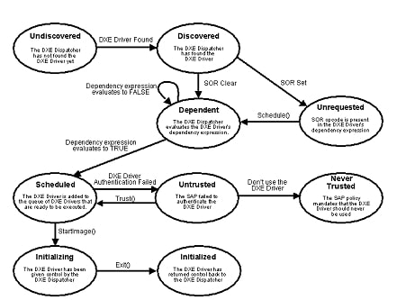
Fig. 10.1 DXE Driver States
A DXE driver starts in the “Undiscovered” state, which means
that the DXE driver is in a firmware volume that the DXE
Dispatcher does not know about yet. When the DXE Dispatcher
discovers a new firmware volume, any DXE drivers from that
firmware volume listed in the a priori file are immediately
loaded and executed. DXE drivers listed in the a priori file
are immediately promoted to the “Scheduled” state. The firmware
volume is then searched for DXE drivers that are not listed in
the a priori file. Any DXE drivers found are promoted from
the “Undiscovered” to the “Discovered” state. The dependency
expression for each DXE driver is evaluated. If the SOR opcode
is present in a DXE driver’s dependency expression, then the
DXE driver is placed in the “Unrequested” state. If the SOR
opcode is not present in the DXE driver’s dependency
expression, then the DXE driver is placed in the “Dependent”
state. Once a DXE driver is in the “Unrequested” state, it may
only be promoted to the “Dependent” state with a call to the
DXE Service Schedule() .
Once a DXE Driver is in the “Dependent” state, the DXE
Dispatcher will evaluate the DXE driver’s dependency
expression. If the DXE driver does not have a dependency
expression, then a dependency expression of all the
architectural protocols ANDed together is assumed for that DXE
driver. If the dependency expression evaluates to FALSE ,
then the DXE driver stays in the “Dependent” state. If the
dependency expression never evaluates to TRUE , then it will
never leave the “Dependent” state. If the dependency expression
evaluates to TRUE , then the DXE driver will be promoted to
the “Scheduled” state.
A DXE driver that is prompted to the “Scheduled” state is added
to the end of the queue of other DXE drivers that have been
promoted to the “Scheduled” state. When the DXE driver has
reached the head of the queue, the DXE Dispatcher must use the
services of the Security Authentication Protocol (SAP) to check
the authentication status of the DXE Driver. If the Security
Authentication Protocol deems that the DXE Driver violates the
security policy of the platform, then the DXE Driver is placed
in the “Untrusted” state. The Security Authentication Protocol
can also tell the DXE Dispatcher that the DXE driver should
never be executed and be placed in the “Never Trusted” state.
If a DXE driver is placed in the “Untrusted” state, it can only
be promoted back to the “Scheduled” state with a call to the
DXE Service Trust() .
Once a DXE driver has reached the head of the scheduled queue,
and the DXE driver has passed the authentication checks of the
Security Authentication Protocol, the DXE driver is loaded into
memory with the Boot Service LoadImage() . Control is then
passed from the DXE Dispatcher to the DXE driver with the Boot
Service StartImage() . When StartImage() is called for a
DXE driver, that DXE driver is promoted to the “Initializing”
state. The DXE driver returns control to the DXE Dispatcher
through the Boot Service Exit() . When a DXE driver has
returned control to the DXE Dispatcher, the DXE driver is in
the terminal state called “Initialized.”
The DXE Dispatcher is responsible for draining the queue of DXE drivers in the “Scheduled” state until the queue is empty. Once the queue is empty, then DXE Dispatcher must evaluate all the DXE drivers in the “Dependent” state to see if any of them need to be promoted to the “Scheduled” state. These evaluations need to be performed every time one or more DXE drivers have been promoted to the “Initialized” state, because those DXE drivers may have produced protocol interfaces for which the DXE drivers in the “Dependent” state are waiting.
10.12. Example Orderings
The order that DXE drivers are loaded and executed by the DXE Dispatcher is a mix of strong and weak orderings. The strong orderings are specified through a priori files, and the weak orderings are specified by dependency expressions in DXE drivers. Sample Firmware Volume shows the contents of a sample firmware volume that contains the following:
DXE Foundation image
DXE driver images
An a priori file
The order that these images appear in the firmware volume is arbitrary. The DXE Foundation and the DXE Dispatcher must not make any assumptions about the locations of files in firmware volumes. The a priori file contains the GUID file names of the DXE drivers that are to be loaded and executed first. The dependency expressions and the protocols that each DXE driver produces is shown next to each DXE driver image in the firmware volume.
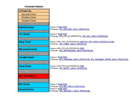
Fig. 10.2 Sample Firmware Volume
Based on the contents of the firmware volume in the figure
above, the Security Driver, Runtime Driver, and Variable Driver
will always be executed first. This is an example of a strongly
ordered dispatch due to the a priori file. The DXE Dispatcher
will then evaluate the dependency expressions of the remaining
DXE drivers to determine the order that they will be executed.
Based on the dependency expressions and the protocols that each
DXE driver produces, there are 30 valid orderings from which
the DXE Dispatcher may choose. The BDS Driver and CPU Driver
tie for the next drivers to be scheduled, because their
dependency expressions are simply TRUE. A dependency
expression of TRUE means that the DXE driver does not require
any other protocol interfaces to be executed. The DXE
Dispatcher may choose either one of these drivers to be
scheduled first. The Timer Driver, Metronome Driver, and Reset
Driver all depend on the protocols produced by the CPU Driver.
Once the CPU Driver has been loaded and executed, the Timer
Driver, Metronome Driver, and Reset Driver may be scheduled in
any order. The table below shows all 30 possible orderings from
the sample firmware volume in the figure above. Each ordering
is listed from left to right across the table. A reasonable
implementation of a DXE Dispatcher would consistently produce
the same ordering for a given system configuration. If the
configuration of the system is changed in any way (including a
order of files stored in a firmware volume), then a different
dispatch ordering may be generated, but this new ordering
should be consistent until the next system configuration
change.
Dispatch Order |
||||||||
|---|---|---|---|---|---|---|---|---|
1 |
2 |
3 |
4 |
5 |
6 |
7 |
8 |
|
1 |
Security |
Runtime |
Variable |
BDS |
CPU |
Timer |
Metronome |
Reset |
2 |
Security |
Runtime |
Variable |
BDS |
CPU |
Timer |
Reset |
Metronome |
3 |
Security |
Runtime |
Variable |
BDS |
CPU |
Metronome |
Timer |
Reset |
4 |
Security |
Runtime |
Variable |
BDS |
CPU |
Metronome |
Reset |
Timer |
5 |
Security |
Runtime |
Variable |
BDS |
CPU |
Reset |
Timer |
Metronome |
6 |
Security |
Runtime |
Variable |
BDS |
CPU |
Reset |
Metronome |
Timer |
7 |
Security |
Runtime |
Variable |
CPU |
BDS |
Timer |
Metronome |
Reset |
8 |
Security |
Runtime |
Variable |
CPU |
BDS |
Timer |
Reset |
Metronome |
9 |
Security |
Runtime |
Variable |
CPU |
BDS |
Metronome |
Timer |
Reset |
10 |
Security |
Runtime |
Variable |
CPU |
BDS |
Metronome |
Reset |
Timer |
11 |
Security |
Runtime |
Variable |
CPU |
BDS |
Reset |
Timer |
Metronome |
12 |
Security |
Runtime |
Variable |
CPU |
BDS |
Reset |
Metronome |
Timer |
13 |
Security |
Runtime |
Variable |
CPU |
Timer |
BDS |
Metronome |
Reset |
14 |
Security |
Runtime |
Variable |
CPU |
Timer |
BDS |
Reset |
Metronome |
15 |
Security |
Runtime |
Variable |
CPU |
Timer |
Metronome |
BDS |
Reset |
16 |
Security |
Runtime |
Variable |
CPU |
Timer |
Metronome |
Reset |
BDS |
17 |
Security |
Runtime |
Variable |
CPU |
Timer |
Reset |
BDS |
Metronome |
18 |
Security |
Runtime |
Variable |
CPU |
Timer |
Reset |
Metronome |
BDS |
19 |
Security |
Runtime |
Variable |
CPU |
Metronome |
Timer |
BDS |
Reset |
20 |
Security |
Runtime |
Variable |
CPU |
Metronome |
Timer |
Reset |
BDS |
21 |
Security |
Runtime |
Variable |
CPU |
Metronome |
BDS |
Timer |
Reset |
22 |
Security |
Runtime |
Variable |
CPU |
Metronome |
BDS |
Reset |
Timer |
23 |
Security |
Runtime |
Variable |
CPU |
Metronome |
Reset |
Timer |
BDS |
24 |
Security |
Runtime |
Variable |
CPU |
Metronome |
Reset |
BDS |
Timer |
25 |
Security |
Runtime |
Variable |
CPU |
Reset |
Timer |
Metronome |
BDS |
26 |
Security |
Runtime |
Variable |
CPU |
Reset |
Timer |
BDS |
Metronome |
27 |
Security |
Runtime |
Variable |
CPU |
Reset |
Metronome |
Timer |
BDS |
28 |
Security |
Runtime |
Variable |
CPU |
Reset |
Metronome |
BDS |
Timer |
29 |
Security |
Runtime |
Variable |
CPU |
Reset |
BDS |
Timer |
Metronome |
30 |
Security |
Runtime |
Variable |
CPU |
Reset |
BDS |
Metronome |
Timer |
10.13. Security Considerations
The DXE Dispatcher is required to use the services of the Security Architectural Protocol every time a firmware volume is discovered and before each DXE driver is executed. Because the Security Architectural Protocol is produced by a DXE driver, there will be at least one firmware volume discovered, and one or more DXE drivers loaded and executed before the Security Architectural Protocol is installed. The DXE Dispatcher should not attempt to use the services of the Security Architectural Protocol until the Security Architectural Protocol is installed. If a platform requires the Security Architectural Protocol to be present very early in the DXE phase, then the a priori file may be used to specify the name of the DXE driver that produces the Security Architectural Protocol.
The Security Architectural Protocol provides a service to evaluate the authentication status of a file. This service can also be used to evaluate the authenticate status of a firmware volume. If the authentication status is good, then no action is taken. If there is a problem with the firmware volume’s authentication status, then the Security Architectural Protocol may perform a platform specific action. One option is to force the DXE Dispatcher to ignore the firmware volume so no DXE drivers will be loaded and executed from it. Another is to log the fact that the DXE Dispatcher is going to start dispatching DXE driver from a firmware volume with a questionable authentication status.
The Security Architectural Protocol can also be used to evaluate
the authentication status of each DXE driver discovered in a
firmware volume. If the authentication status is good, then no
action is taken. If there is a problem with the DXE driver’s
authentication status, then the Security Architectural Protocol
may take a platform-specific action. One possibility is to force
the DXE driver into the “Untrusted” state, so it will not be
considered for dispatch until the Boot Service Trust() is called
for that DXE driver. Another possibility is to have the DXE
Dispatcher place the DXE driver in the “Never Trusted” state, so
it will never be loaded or executed. Another option is to log the
fact that a DXE driver with a questionable authentication status
is about to be loaded and executed.