17. I2C Protocol Stack
17.1. Design Discussion
The Inter-Integrated Circuit (I2C) protocol stack enables third party silicon vendors to write UEFI drivers for their products by decoupling the I2C chip details from the I2C controller and I2C bus configuration details.
17.1.1. I2C Bus Overview
` <http://www.acpi.info/spec.htm>`__The Inter-Integrated Circuit (|I2C|) bus enables simple low speed communications between chips. The following sections describe the attributes of the |I2C| bus configurations supported by the |I2C| protocol stack and the |I2C|-bus specification and user manual .
17.1.1.1. SingleMaster
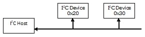
Fig. 17.1 Simple 12C Bus
Simple 12C Bus shows a simple I2C bus configuration consisting of one host controller and two I2C devices which use the same I2C clock frequency. In this configuration the I2C host controller gets initialized with a single clock frequency and performs transactions to the I2C devices using their slave addresses.
17.1.1.2. Multiple I2C Bus Frequencies
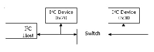
Fig. 17.2 Multiple I2C Bus Frequencies
Two I2C bus configurations are shown in Multiple I2C Bus Frequencies, separated by a switch. This allows the I2C bus to operate at two different frequencies depending on the state of the switch. Device requiring higher bus frequencies are placed closer to the I2C host controller and are accessed when the switch is turned off. Devices using lower bus frequencies are placed after the switch and may only be accessed when the switch is on. Note that the I2C bus frequency needs to be set to a frequency supported by all devices currently accessible by the I2C host controller.
17.1.1.3. Limited Address Space
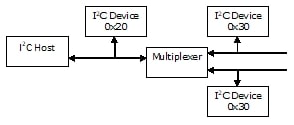
Fig. 17.3 Limited Address Space
17.1.1.4. I2C Bus Configurations
A bus configuration is a concept introduced by the I2C protocol stack to configure the state of the switches and multiplexers in the I2C bus. The I2C protocol stack calls into the platform code with a value from zero (0) to N-1 to request the platform code enable a specific configuration of the switches and multiplexers. The platform code then sets the requested state for the switches and multiplexers and sets the I2C clock frequency for this I2C bus configuration. Upon return the I2C protocol stack is able to access the I2C devices in this configuration.
17.1.2. 2C Protocol Stack Overview
The following is a representation of the I2C protocol stack and an I2C bus layout.
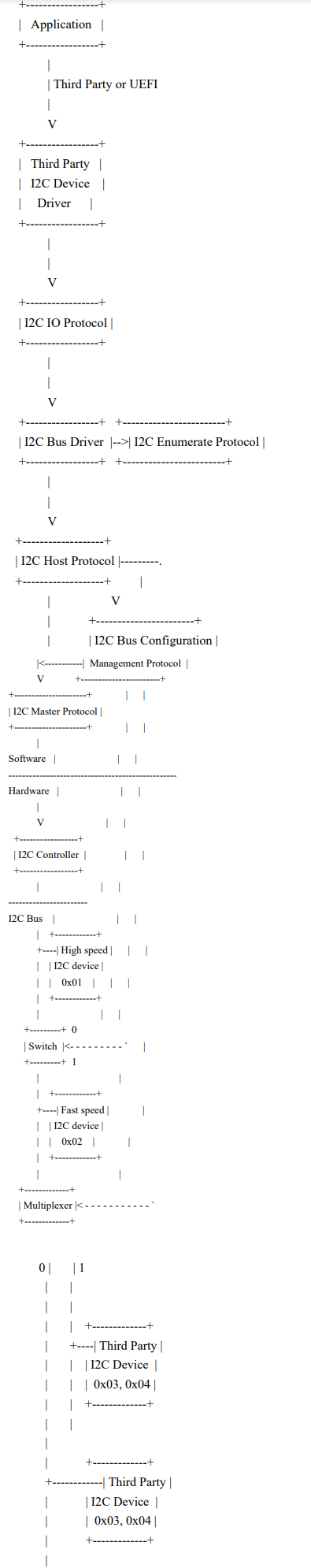
Fig. 17.4 I2C Protocol Stack
I2C Protocol Stack The platform hardware designer chooses the bus layout based upon the platform, I2C chip and software requirements. The design uses switches to truncate the bus to enable higher bus frequencies for a subset of devices which are placed closer to the controller. When the switch is on, the extended bus must operate at a lower bus frequency. The design uses multiplexer to create separate address spaces enabling the use of multiple devices which would otherwise have conflicting addresses. See the |I2C|-bus specification and user manual for more details.
N.B. Some operating systems may prohibit the changing of switches and multiplexers in the I2C bus. In this case the platform hardware and software designers must select a single I2C bus configuration consisting of constant input values for the switches and multiplexers. The I2C subsystem must be placed in the OS compatible I2C bus configuration upon successful completion of ExitBootServices() .
The platform hardware designer needs to provide the platform software designer the following data for each I2C bus:
Which controller controls this bus
A list of logic blocks contained in one or more I2C devices:
I2C device which contains this logic block
Logic block I2C slave address
Logic block description
For each configuration of the switches and multiplexers in the I2C bus
What is the maximum frequency of operation for the I2C bus
What I2C slave addresses are accessible
The settings for the switches and multiplexers when control is given to the operating system.
17.1.2.1. Handles
The I2C protocol stack uses two groups of handles:
I2C controller handles
I2C device handles
Some bus driver (PCI, USB, etc.) or the platform specific code may expose a handle for each of the I2C controllers. The platform specific code installs the I2C bus configuration management and I2C enumeration protocols on the controller handle. As the I2C stack is initialized, additional protocols are placed on the I2C controller handle. When the I2C stack initialization is complete, the controller handle contains:
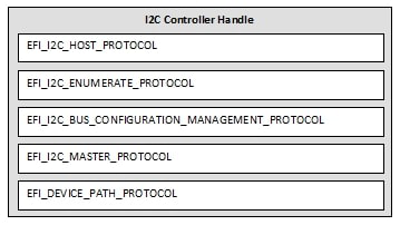
Fig. 17.5 Controller Handle After I2C Stack Initialization
The I2C Bus Driver uses the EFI_I2C_ENUMERATE_PROTOCOL to enumerate the set of I2C devices connected to an I2C controller, and creates an I2C device handle for each I2C device installing the following protocols on each:
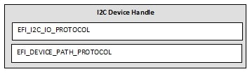
Fig. 17.6 I2C Protocol Stack after EFI_I2C_ENUMERATE_PROTOCOL
It is possible for the SMBus Host Controller Protocol to be implemented using the services on an I2C Controller Handle. The SMBus Host Controller Protocol does not support the concept of multiple bus configurations, so the state of the I2C controller handle required for the SMBus Host Controller Protocol to be produced on an I2C Controller Handle is as follows:
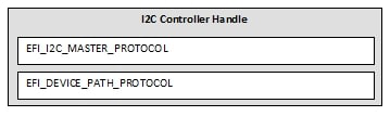
Fig. 17.7 State of the Required I2C Controller Handle
17.1.2.2. Driver Loading Order
A race condition potentially exists between the platform specific code and a layered SMBus driver when a driver for a PCI or USB I2C controller installs the EFI_I2C_MASTER_PROTOCOL on its handle. The layered SMBus driver may start on this controller as soon as the EFI_I2C_MASTER_PROTOCOL is installed as long as the EFI_I2C_BUS_CONFIGURATION_MANAGEMENT_PROTOCOL is not installed on the controller handle. However if the platform specific code wants to use this controller with the EFI_I2C_HOST_PROTOCOL then the platform specific code needs to prevent the SMBus driver from starting by installing the EFI_I2C_BUS_CONFIGURATION_MANAGEMENT_PROTOCOL . Note that the I2C host protocol opens the EFI_I2C_MASTER_PROTOCOL only if the handle contains the EFI_I2C_BUS_CONFIGURATION_MANAGEMENT_PROTOCOL .
Chapter 10 of the Universal Extensible Firmware Interface Specification describes several ways for the platform specific code to adjust the driver load order. One possible way to eliminate this race condition is to use the version number for the driver binding protocol. The platform specific code implements the driver binding protocol’s Supported() and Start() routines and sets the version field to a value in the range of 0xfffffff0 - 0xffffffff . The SMBus driver should set the version field of the driver binding protocol to a value in the range of 0x00000010 - 0xffffffef . This selection delays the SMBus driver to execute its Supported() and Start() routines after the platform specific code, enabling the platform specific code to install the EFI_I2C_BUS_CONFIGURATION_MANAGEMENT_PROTOCOL and the EFI_I2C_ENUMERATE_PROTOCOL on the controller’s handle.
17.1.2.3. Third Party I2C Drivers
Third party I2C drivers are I2C chip specific but platform and host controller independent.
Third party I2C driver writers, typically silicon vendors, need to provide:
The vendor specific GUID that is used to select their driver.
I2C slave address array guidance (described below) when the I2C device uses more than one I2C slave address consisting of the order for the blocks of logic that get referenced by the entries in the slave address array.
The hardware version of the I2C device, this value is passed to the third party I2C driver to enable it to perform workarounds for the specific hardware version. It is recommended that value match the value in the ACPI _HRV tag. See the Advanced Configuration and Power Interface Specification, Revision 5.0 for the field format and the Plug and play support for |I2C| web-page for restriction on values.
The third party I2C driver uses relative addressing to abstract the platform specific details of the I2C device. Using an example I2C device containing an accelerometer and a magnetometer which consumes two I2C slave addresses, one for each logic block. The third party I2C driver writer may choose to write two drivers, one for each block of logic, in which case each driver refers to the single I2C slave address using the relative value of zero (0). However if the third party I2C driver writer chooses to write a single driver which consumes multiple I2C slave addresses then the third party I2C driver writer needs to convey the order of the I2C slave address entries in the I2C slave address array to the platform software designer. For the example:
The platform hardware designer picks the actual slave addresses from the I2C device’s data sheet and provides this information to the platform software designer. The platform software designer then places the I2C slave addresses into the I2C slave address array in the EFI_I2C_ENUMERATE_PROTOCL in the order specified by the third party I2C driver writer. The third party I2C driver writer uses the index into the I2C slave address array as the relative I2C slave address. The I2C IO protocol uses the I2C slave address array to translate the relative I2C slave address into the platform specific I2C slave address. The relative value always starts at zero (0) and its maximum value is the number of entries in I2C slave address array minus one.
Each I2C slave address entry is specified as a 32-bit integer to allow room for future I2C slave address expansion. Only the I2C master protocol knows the maximum I2C slave address value. All other drivers and applications must look for the EFI_NOT_FOUND status for the indication that a reserve bit was set in the I2C slave address.
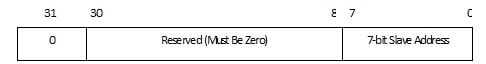
Fig. 17.8 v5 i2c protocol stack

Fig. 17.9 v5 i2c protocol stack
17.1.2.3.1. Driver Binding Protocol Supported() API
The driver binding protocol’s Supported() routine looks for controllers which declare the EFI_I2C_IO_PROTOCOL and match the device path supplied by the silicon vendor or third party I2C driver writer to the platform integrator.
The third party I2C device driver creates a GUID for a Vendor-Defined Hardware Device Path Node when describing the I2C device. The third party I2C device driver writer provides this GUID to the person writing the platform specific code to identify the type of I2C device.
The third party I2C driver which consumes the EFI_I2C_IO_PROTOCOL compares the known GUID with the GUID pointed to by the DeviceGuid field.
An example algorithm for the driver binding protocol Supported() routine:
Open the EFI_I2C_IO_PROTOCOL using EFI_OPEN_PROTOCOL_BY_DRIVER
If OpenProtocol() fails return the error status
Get the vendor GUID from the EFI_I2C_IO_PROTOCOL
Close the EFI_I2C_IO_PROTOCOL
Compare the expected vendor GUID to the GUID from the EFI_I2C_IO_PROTOCOL structure.
If the GUIDS don’t match then return EFI_NOT_SUPPORTED
Return EFI_SUCCESS
17.1.2.3.2. Supporting Multiple Hardware Versions
Note that package markings are important to allow the platform integrator to verify the hardware revision after the part is integrated! The platform integrator includes the hardware revision information into the EFI_I2C_ENUMERATE_PROTOCOL . The I2C bus driver gets this data during the I2C device enumeration and makes it available to the third party I2C device driver via the EFI_I2C_IO_PROTOCOL . There are a couple of ways in which the silicon vendor or third party I2C driver writer may support multiple hardware versions of the I2C device:
Provide a different GUID value to the platform integrator for each hardware revision
Provide a different hardware version value to the platform integrator with the devices
Each of the above methods describes an interface to the I2C device. The interface specifies the number of slave addresses as well as the features and software workarounds for the I2C device.
17.1.2.4. I2C IO Protocol
The I2C IO protocol is platform, host controller, and I2C chip independent.
The I2C bus driver creates a handle for each of the I2C devices returned by the I2C enumerate protocol. The I2C controller’s device path is extended with the vendor GUID and unique ID value returned by the I2C enumerate protocol and attached to the handle. The vendor GUID is used to extend the device path with a Vendor-define Hardware Device Path Node and the unique ID is used to further extend the device path with a Controller Device Path Node. If the unique ID is 0, then the Controller Device Path Node is optional. The third party I2C device driver uses the device GUID to determine if it may connect.
When a third party I2C device driver or application calls QueueRequest() , the I2C IO protocol validates the SlaveAddressIndex (relative I2C address) for the I2C device and then converts the SlaveAddressIndex to a I2C slave address. The request is then passed to the I2C host protocol along with the tuple BusConfiguration:I2C slave address.
17.1.2.5. I2C Host Protocol
The I2C host protocol is platform, host controller, and I2C chip independent.
Note
For proper operation of the I2C bus, only the I2C IO protocol and I2C test applications connect to the EFI_I2C_HOST_PROTOCOL .
The I2C host protocol may access any device on the I2C bus. The I2C host protocol has the following responsibilities:
Limits the number of requests to the I2C master protocol to one. The I2C host protocol holds on to additional requests until the I2C master protocol is available to process the request. The I2C requests are issued in FIFO order to the I2C master protocol.
Enable the proper I2C bus configuration before starting the I2C request using the I2C master protocol
I2C devices are addressed as the tuple: BusConfiguration:SlaveAddress. I2C bus configuration zero (0) is the portion of the I2C bus that connects to the host controller. The bus configuration specifies the control values for the switches and multiplexers in the I2C bus. After the switches and multiplexers are properly configured, the I2C controller uses the slave address to access the requested I2C device.
Since the I2C protocol stack supports asynchronous transactions the I2C host protocol maintains a queue of I2C requests until the I2C controller is available them. When a request reaches the head of the queue the necessary bus configuration is enabled and then the request is sent to the I2C master protocol.
17.1.2.6. I2C Master Protocol
The I2C master protocol is I2C controller specific but platform independent.
This protocol is designed to allow the implementation to be built as a driver which may be delivered in binary form as an EFI image.
The master protocol manipulates the I2C controller to perform a transaction on the I2C bus. The I2C master protocol does not configure the I2C bus so it is up to the caller to ensure that the I2C bus is in the proper configuration before issuing the I2C request.
The I2C master protocol typically needs the following information:
Host controller address
Controller’s input clock frequency
Depending upon the I2C controller, more data may be necessary. This protocol may use any method to get these values: hard coded values, PCD values, or may choose to communicate with the platform specific code using an undefined mechanism to get these values.
If the I2C master protocol requires data from the platform specific code then the I2C master protocol writer needs to provide the platform interface details to the platform software designer.
17.1.2.7. Platform Specific Code
The platform specific code installs the EFI_I2C_ENUMERATE_PROTOCOL to provide the I2C device descriptions to the I2C bus driver using the EFI_I2C_DEVICE structure. These descriptions include the bus configuration number required for the I2C device, the slave address array, the vendor GUID and a unique ID value.
The EFI_I2C_BUS_CONFIGURATION_MANAGEMENT_PROTOCOL enables the I2C host protocol to call into the platform specific code to enable a specific I2C bus configuration and set the I2C bus frequency. This protocol is required to get the I2C host protocol to start for the I2C controller’s handle.
The platform software designer collects the data requirements from third party I2C driver writers, the vendor specific I2C master protocol writer, the EFI_I2C_BUS_CONFIGURATION_MANAGEMENT_PROTOCOL and EFI_I2C_ENUMERATE_PROTOCOL . The platform software designer gets the necessary data from the platform hardware designer. The platform software designer then builds the data structures and implements the necessary routines to construct the platform specific code for I2C.
17.1.2.8. Switches and Multiplexers
There are some I2C switches and I2C multiplexers where the control is done via I2C commands. When the control inputs come via the same I2C bus that is being configured then the platform specific code must use the EFI_I2C_MASTER_PROTOCOL . While the I2C host protocol makes the call to EnableI2cBusConfiguration to configure the I2C bus, the I2C host protocol keeps the I2C master protocol idle, enabling the platform specific code to perform the necessary I2C configuration transactions.
If however the configuration control is done via an I2C device connected to a different I2C bus (host controller), then the platform software designer may choose between the following:
Call into a third party I2C driver to manipulate the I2C bus control device.
Call into the EFI_I2C_IO_PROTOCOL if no third party I2C driver exists for the I2C bus control device
Call into the EFI_I2C_HOST_PROTOCOL if the platform does not expose the I2C bus control device.
17.1.3. PCI Comparison
PCI provides several features to describe the device to the operating system as well decoupling the driver from the specific platform.
17.1.3.1. Device Description
PCI uses the Vendor ID and Device ID fields in configuration space to identify the piece of hardware. Where the Vendor ID is assigned by the PCI committee and the Device ID is assigned by the hardware manufacture.
PCI also uses the Base Class , Sub Class and Programming Interface fields to help identify the operating system driver.
The I2C protocol stack uses the vendor GUID associated with the I2C device to identify the UEFI driver. This GUID is supplied by the silicon vendor or third party I2C driver writer to the platform integrator and gets included in the I2C platform driver. The EFI_I2C_ENUMERATE_PROTOCOL provides this GUID to the I2C bus driver during the I2C bus enumeration.
The driver binding protocol’s Supported() routine of the third party I2C device driver looks for controllers which have the EFI_I2C_IO_PROTOCOL and have a match for the vendor GUID.
17.1.3.2. Hardware Features and Workarounds
PCI provides a Revision ID field to allow the driver to determine which version of hardware is present and which features and software workarounds are necessary to support this device.
The I2C protocol stack uses the HardwareRevision field in the EFI_I2C_IO_PROTOCOL for this same purpose. It is recommended that this value match the _HRV value in the DSDT for this I2C device. See the Advanced Configuration and Power Interface Specification, Revision 5.0 for the field format and the Plug and play support for |I2C| web-page for restriction on values.
17.1.3.3. Device Relative Addressing
PCI provides Base Address Registers (BARs) to decouple the device driver software from the details of the platform’s PCI bus configuration. Typically, all device register references are fixed offsets from one of the BAR addresses.
The I2C protocol stack provides a similar mechanism using an index into an array of slave addresses. The silicon vendor or third party driver writer provides the structure of the array listing the major functions to the platform integrator. An example is:
The platform integrator works with the platform’s hardware designer to get the I2C slave addresses of the I2C device and builds the array which is included in the platform specific code. During I2C device enumeration, this array is passed to the I2C bus driver for use by the I2C IO protocol.
The third party I2C driver references the major components within the I2C device using the index values, thus remaining platform independent. The I2C IO protocol performs the array lookup, translating the index into an actual slave address on the I2C bus.
Most I2C devices only have a single I2C slave address and thus the third party I2C device driver will only use index zero (0). Also depending upon the I2C device architecture, the silicon vendor or third party I2C device writer may choose to write multiple drivers, each supporting a single I2C slave address.
17.1.4. Hot Plug Support
I2C protocol stack enables the platform specific code to support hot-plug with the following algorithm:
Describe all possible devices on all possiblebusses, including the hot-plug devices.
The platform specific code detects hot-plug events: Add and Remove
For a removal event:
The platform specific code opens the EFI_I2C_IO_PROTOCOL on the hot-plug device’s handle exclusively. This operation tears down any upper layer protocols on this handle. Note that the open request may fail if I/O is pending in the lower protocols.
When the step above fails, delay below TPL_NOTIFY to allow the current I
2C transaction complete and then retry until the open is successful
After the open is successful, the platform specific code may use the I
2C IO protocol to perform I2C transactions for device probing.
For an add event:
The platform specific code waits for completion any outstanding I/O that the platform specific code initiated on the hot-plug I2C device.
The platform specific code closes the EFI_I2C_IO_PROTOCOL
The platform specific code issues a ConnectController() on the hot-plug device’s handle. This causes the protocol stack which uses the hot-plug device to be reloaded.
17.2. DXE Code definitions
The I2C protocol stack consists of the following protocols:
EFI_I2C_IO_PROTOCOL - Third party silicon vendors use this protocol to access their I2C device. This protocol enables a driver or application to perform I/O transactions to a single I2C device independent of the I2C bus configuration.
EFI_I2C_HOST_PROTOCOL - The I2C bus driver uses this protocol to produce the EFI_I2C_IO_PROTOCOL that provides access a device on the I2C bus.
EFI_I2C_MASTER_PROTOCOL - The I2C host protocol uses this protocol to manipulate the I2C host controller and perform transactions as a master on the I2C bus.
EFI_I2C_BUS_CONFIGURATION_MANAGEMENT_PROTOCOL - The I2C host protocol uses this protocol to request the proper state for the switches and multiplexers in the I2C bus and set the I2C clock frequency.
EFI_I2C_ENUMERATE_PROTOCOL - The I2C bus driver uses this protocol to enumerate the devices on the I2C bus, getting the bus configuration and an array of slave addresses for each of the I2C devices.
The following sections describe these protocols in detail.
17.2.1. I2C Master Protocol
17.2.2. EFI_I2C_MASTER_PROTOCOL
Summary
This protocol manipulates the I2C host controller to perform transactions as a master on the I2C bus using the current state of any switches or multiplexers in the I2C bus.
GUID
#define EFI_I2C_MASTER_PROTOCOL_GUID \
{ 0xcd72881f, 0x45b5, 0x4feb, { 0x98, 0xc8, 0x31, 0x3d, \
0xa8, 0x11, 0x74, 0x62 }}
Protocol Interface Structure
typedef struct \_EFI_I2C_MASTER_PROTOCOL {
  EFI_I2C_MASTER_PROTOCOL_SET_BUS_FREQUENCY  SetBusFrequency;
  EFI_I2C_MASTER_PROTOCOL_RESET              Reset;
  EFI_I2C_MASTER_PROTOCOL_START_REQUEST      StartRequest;
  CONST EFI_I2C_CONTROLLER_CAPABILITIES *I2cControllerCapabilities;
} EFI_I2C_MASTER_PROTOCOL;
Parameters
- SetBusFrequency
Set the clock frequency for the I2C bus.
- Reset
Reset the I2C host controller.
- StartRequest
Start an I2C transaction in master mode on the host controller.
- I2cControllerCapabilities
Pointer to an EFI_I2C_CONTROLLER_CAPABILITIES data structure containing the capabilities of the I2C host controller.
Description
The EFI_I2C_MASTER_PROTOCOL is typically used by the I2C host protocol to perform transactions on the I2C bus. This protocol may also be used to configure the I2C clock frequency and use I2C transactions to set the state of switches and multiplexers in the I2C bus.


A 10-bit slave address is or’ed with the following value enabling the I2C protocol stack to address the duplicated address space between 0 and 127 in 10-bit mode.
#define I2C_ADDRESSING_10_BIT 0x80000000
The I2C protocol stack uses the EFI_I2C_REQUEST_PACKET structure to describe I2C transactions on the I2C bus. The EFI_I2C_OPERATION describes a portion of the I2C transaction. The transaction starts with a start bit followed by the first operation in the operation array. Subsequent operations are separated with repeated start bits and the last operation is followed by a stop bit which concludes the transaction.
typedef struct {
  UINTN                   OperationCount;
  EFI_I2C_OPERATION       Operation[];
} EFI_I2C_REQUEST_PACKET;
Parameters
- OperationCount
Number of elements in the operation array.
- Operation
Description of the I2C operation
Description
The EFI_I2C_REQUEST_PACKET describes a single I2C transaction. The transaction starts with a start bit followed by the first operation in the operation array. Subsequent operations are separated with repeated start bits and the last operation is followed by a stop bit which concludes the transaction. Each operation is described by one of the elements in the Operation array.
typedef struct {
  UINT32             Flags;
  UINT32             LengthInBytes;
  UINT8              *Buffer;
} EFI_I2C_OPERATION;
Parameters
- Flags
Flag bits qualify the I2C operation.
Flag Bits:
///
/// Define the I2C flags
///
/// I2C read operation when set
#define I2C_FLAG_READ               0x00000001

///
/// Define the flags for SMBus operation
///
/// The following flags are also present in only the first I2C operation
/// and are ignored when present in other operations. These flags
/// describe a particular SMB transaction as shown in the following table.
///

/// SMBus operation
#define I2C_FLAG_SMBUS_OPERATION 0x00010000

/// SMBus block operation
/// The flag I2C_FLAG_SMBUS_BLOCK causes the I2C master protocol to update
/// the LengthInBytes field of the operation in the request packet with
/// the actual number of bytes read or written. These values are only
/// valid when the entire I2C transaction is successful.
/// This flag also changes the LengthInBytes meaning to be: A maximum
/// of LengthInBytes is to be read from the device. The first byte
/// read contains the number of bytes remaining to be read, plus an
/// optional PEC value.
#define I2C_FLAG_SMBUS_BLOCK 0x00020000

/// SMBus process call operation
#define I2C_FLAG_SMBUS_PROCESS_CALL 0x00040000

/// SMBus use packet error code (PEC)
///   Note that the I2C master protocol may clear the I2C_FLAG_SMBUS_PEC bit
/// to indicate that the PEC value was checked by the hardware and is
/// not appended to the returned read data.
///
#define I2C_FLAG_SMBUS_PEC 0x00080000

//----------------------------------------------------------------------
///
/// QuickRead:          OperationCount=1,
///                     LengthInBytes=0,   Flags=I2C_FLAG_READ
/// QuickWrite:         OperationCount=1,
///                     LengthInBytes=0,   Flags=0
///
///
/// ReceiveByte:        OperationCount=1,
///                     LengthInBytes=1, Flags=I2C_FLAG_SMBUS_OPERATION
///                                              | I2C_FLAG_READ
/// ReceiveByte+PEC:    OperationCount=1,
///                     LengthInBytes=2, Flags=I2C_FLAG_SMBUS_OPERATION
///                                              | I2C_FLAG_READ
///                                           | I2C_FLAG_SMBUS_PEC
///
///
/// SendByte:           OperationCount=1,
///                     LengthInBytes=1, Flags=I2C_FLAG_SMBUS_OPERATION
/// SendByte+PEC:       OperationCount=1,
///                     LengthInBytes=2, Flags=I2C_FLAG_SMBUS_OPERATION
///                                           | I2C_FLAG_SMBUS_PEC
///
///
/// ReadDataByte:       OperationCount=2,
///                     LengthInBytes=1, Flags=I2C_FLAG_SMBUS_OPERATION
///                     LengthInBytes=1, Flags=I2C_FLAG_READ
/// ReadDataByte+PEC:   OperationCount=2,
///                     LengthInBytes=1, Flags=I2C_FLAG_SMBUS_OPERATION
///                                           | I2C_FLAG_SMBUS_PEC
///                     LengthInBytes=2, Flags=I2C_FLAG_READ
///
///
/// WriteDataByte:      OperationCount=1,
///                     LengthInBytes=2, Flags=I2C_FLAG_SMBUS_OPERATION
/// WriteDataByte+PEC: OperationCount=1,
///                     LengthInBytes=3, Flags=I2C_FLAG_SMBUS_OPERATION
///                                           | I2C_FLAG_SMBUS_PEC
///
///
/// ReadDataWord:       OperationCount=2,
///                     LengthInBytes=1, Flags=I2C_FLAG_SMBUS_OPERATION
///                     LengthInBytes=2, Flags=I2C_FLAG_READ
/// ReadDataWord+PEC:   OperationCount=2,
///                     LengthInBytes=1, Flags=I2C_FLAG_SMBUS_OPERATION
///                                          | I2C_FLAG_SMBUS_PEC
///                     LengthInBytes=3, Flags=I2C_FLAG_READ
///
///
/// WriteDataWord:      OperationCount=1,
///                     LengthInBytes=3, Flags=I2C_FLAG_SMBUS_OPERATION
/// WriteDataWord+PEC:  OperationCount=1,
///                     LengthInBytes=4, Flags=I2C_FLAG_SMBUS_OPERATION
///                                          | I2C_FLAG_SMBUS_PEC
///
///
/// ReadBlock:          OperationCount=2,
///                     LengthInBytes=1, Flags=I2C_FLAG_SMBUS_OPERATION
///                                          | I2C_FLAG_SMBUS_BLOCK
///                     LengthInBytes=33, Flags=I2C_FLAG_READ
/// ReadBlock+PEC:      OperationCount=2,
///                     LengthInBytes=1, Flags=I2C_FLAG_SMBUS_OPERATION
///                                          | I2C_FLAG_SMBUS_BLOCK
///                                          | I2C_FLAG_SMBUS_PEC
///                     LengthInBytes=34, Flags=I2C_FLAG_READ
///
///
/// WriteBlock:         OperationCount=1,
///                     LengthInBytes=N+2, Flags=I2C_FLAG_SMBUS_OPERATION
///                                          | I2C_FLAG_SMBUS_BLOCK
/// WriteBlock+PEC:     OperationCount=1,
///                     LengthInBytes=N+3, Flags=I2C_FLAG_SMBUS_OPERATION
///                                          | I2C_FLAG_SMBUS_BLOCK
///                                          | I2C_FLAG_SMBUS_PEC
///
///
/// ProcessCall:        OperationCount=2,
///                     LengthInBytes=3, Flags=I2C_FLAG_SMBUS_OPERATION
///                                          | I2C_FLAG_SMBUS_PROCESS_CALL
///                     LengthInBytes=2, Flags=I2C_FLAG_READ
/// ProcessCall+PEC:    OperationCount=2,
///                     LengthInBytes=3, Flags=I2C_FLAG_SMBUS_OPERATION
///                                          | I2C_FLAG_SMBUS_PROCESS_CALL
///                                          | I2C_FLAG_SMBUS_PEC
///                     LengthInBytes=3, Flags=I2C_FLAG_READ
///
///
/// BlkProcessCall:     OperationCount=2,
///                     LengthInBytes=N+2, Flags=I2C_FLAG_SMBUS_OPERATION
///                                          | I2C_FLAG_SMBUS_PROCESS_CALL
///                                          | I2C_FLAG_SMBUS_BLOCK
///                     LengthInBytes=33, Flags=I2C_FLAG_READ
/// BlkProcessCall+PEC: OperationCount=2,
///                     LengthInBytes=N+2, Flags=I2C_FLAG_SMBUS_OPERATION
///                                          | I2C_FLAG_SMBUS_PROCESS_CALL
///                                          | I2C_FLAG_SMBUS_BLOCK
///                                          | I2C_FLAG_SMBUS_PEC
///                     LengthInBytes=34, Flags=I2C_FLAG_READ
///
//----------------------------------------------------------------------
- LengthInBytes
Number of bytes to send to or receive from the I2C device. A ping (address only byte/bytes) is indicated by setting the LengthInBytes to zero.
- Buffer
Pointer to a buffer containing the data to send or to receive from the I2C device. The Buffer must be at least LengthInBytes in size.
Description
The EFI_I2C_OPERATION describes a subset of an I2C transaction in which the I2C controller is either sending or receiving bytes from the bus. Some transactions will consist of a single operation while others will be two or more.
Note
Some I2C controllers do not support read or write ping (address only) operation and will return EFI_UNSUPPORTED status when these operations are requested.
Note
I2C controllers which do not support complex transactions requiring multiple repeated start bits return EFI_UNSUPPORTED without processing any of the transaction.
typedef struct {
  UINT32   StructureSizeInBytes;
  UINT32   MaximumReceiveBytes;
  UINT32   MaximumTransmitBytes;
  UINT32   MaximumTotalBytes;
} EFI_I2C_CONTROLLER_CAPABILITIES;
Parameters
- StructureSizeInBytes
Length of this data structure in bytes
- MaximumReceiveBytes;
The maximum number of bytes the I2C host controller is able to receive from the I2C bus.
- MaximumTransmitBytes
The maximum number of bytes the I2C host controller is able to send on the I2C bus.
- MaximumTotalBytes
The maximum number of bytes in the I2C bus transaction.
Description
The EFI_I2C_CONTROLLER_CAPABILITIES specifies the capabilities of the I2C host controller. The StructureSizeInBytes enables variations of this structure to be identified if there is need to extend this structure in the future.
17.2.3. EFI_I2C_MASTER_PROTOCOL.SetBusFrequency()
Summary
Set the frequency for the I2C clock line.
Prototype
typedef
EFI_STATUS
(EFIAPI *EFI_I2C_MASTER_PROTOCOL_SET_BUS_FREQUENCY) (
  IN CONST EFI_I2C_MASTER_PROTOCOL    *This,
  IN OUT UINTN                        *BusClockHertz
  );
Parameters
- This
Pointer to an EFI_I2C_MASTER_PROTOCOL structure.
- BusClockHertz
Pointer to the requested I2C bus clock frequency in Hertz. Upon return this value contains the actual frequency in use by the I2C controller.
Description
This routine must be called at or below TPL_NOTIFY .
The software and controller do a best case effort of using the specified frequency for the I2C bus. If the frequency does not match exactly then the I2C master protocol selects the next lower frequency to avoid exceeding the operating conditions for any of the I2C devices on the bus. For example if 400 KHz was specified and the controller’s divide network only supports 402 KHz or 398 KHz then the I2C master protocol selects 398 KHz. If there are not lower frequencies available, then return EFI_UNSUPPORTED .
Status Codes Returned
EFI_SUCCESS |
The bus frequency was set successfully. |
EFI_ALREADY_STARTED |
The controller is busy with another transaction. |
EFI_UNSUPPORTED |
The controller does not support this frequency. |
17.2.4. EFI_I2C_MASTER_PROTOCOL.Reset()
Summary
Reset the I2C controller and configure it for use.
Prototype
typedef
EFI_STATUS
(EFIAPI *EFI_I2C_MASTER_PROTOCOL_RESET) (
  IN CONST EFI_I2C_MASTER_PROTOCOL  *This
  );
Parameters
- This
Pointer to an EFI_I2C_MASTER_PROTOCOL structure.
Description
This routine must be called at or below TPL_NOTIFY .
The I2C controller is reset. The caller must call SetBusFrequency() after calling Reset() .
Status Codes Returned
EFI_SUCCESS |
The rest completed successfully. |
EFI_ALREADY_STARTED |
The controller is busy with another transaction. |
EFI_DEVICE_ERROR |
The reset operation failed. |
17.2.5. EFI_I2C_MASTER_PROTOCOL.StartRequest()
Summary
Start an I2C transaction on the host controller.
Prototype
typedef
EFI_STATUS
(EFIAPI *EFI_I2C_MASTER_PROTOCOL_START_REQUEST) (
  IN CONST EFI_I2C_MASTER_PROTOCOL   *This,
  IN UINTN                           SlaveAddress,
  IN EFI_I2C_REQUEST_PACKET          *RequestPacket,
  IN EFI_EVENT                       Event          OPTIONAL,
  OUT EFI_STATUS                     *I2cStatus     OPTIONAL
  );
Parameters
- This
Pointer to an EFI_I2C_MASTER_PROTOCOL structure.
- SlaveAddress
Address of the device on the I2C BUS. Set the I2C_ADDRESSING_10_BIT when using 10-bit addresses, clear this bit for 7-bit addressing. Bits 0-6 are used for 7-bit I2C slave addresses and bits 0-9 are used for 10-bit I2C slave addresses.
- RequestPacket
Pointer to an EFI_I2C_REQUEST_PACKET structure describing the I2C transaction.
- Event
Event to signal for asynchronous transactions, NULL for synchronous transactions
- I2cStatus
Optional buffer to receive the I2C transaction completion status
Description
This routine must be called at or below TPL_NOTIFY . For synchronous requests this routine must be called at or below TPL_CALLBACK .
This function initiates an I2C transaction on the controller. To enable proper error handling by the I2C protocol stack, the I2C master protocol does not support queuing but instead only manages one I2C transaction at a time. This API requires that the I2C bus is in the correct configuration for the I2C transaction.
The transaction is performed by sending a start-bit and selecting the I2C device with the specified I2C slave address and then performing the specified I2C operations. When multiple operations are requested they are separated with a repeated start bit and the slave address. The transaction is terminated with a stop bit.
When Event is NULL, StartRequest operates synchronously and returns the I2C completion status as its return value.
When Event is not NULL, StartRequest synchronously returns EFI_SUCCESS indicating that the I2C transaction was started asynchronously. The transaction status value is returned in the buffer pointed to by I2cStatus upon the completion of the I2C transaction when I2cStatus is not NULL. After the transaction status is returned the Event is signaled.
Note
The typical consumer of this API is the I2C host protocol. Extreme care must be taken by other consumers of this API to prevent confusing the third party I2C drivers due to a state change at the I2C device which the third party I2C drivers did not initiate. I2C platform specific code may use this API within these guidelines.
Status Codes Returned
EFI_SUCCESS |
The asynchronous transaction was successfully started when Event is not NULL |
EFI_SUCCESS |
The transaction completed successfully when Event is NULL |
EFI_ALREADY_STARTED |
The controller is busy with another transaction |
EFI_BAD_BUFFER_SIZE |
The RequestPacket LengthInBytes value is too large |
EFI_DEVICE_ERROR |
There was an I2C error NACK during the transaction |
EFI_INVALID_PARAMETER |
RequestPacket is NULL |
EFI_NOT_FOUND |
Reserved bit set in the SlaveAddress parameter |
EFI_NO_RESPONSE |
The I2C device is not responding to the slave address EFI_DEVICE_ERROR will be returned if the controller cannot distinguish when the NACK occurred |
EFI_OUT_OF_RESOURCES |
Insufficient memory for I2C transaction |
EFI_UNSUPPORTED |
The controller does not support the requested transaction |
17.2.6. I2C Host Protocol
17.2.7. EFI_I2C_HOST_PROTOCOL
Summary
This protocol provides callers with the ability to do I/O transactions to all of the devices on the I2C bus.
GUID
#define EFI_I2C_HOST_PROTOCOL_GUID \
{ 0xa5aab9e3, 0xc727, 0x48cd, { 0x8b, 0xbf, 0x42, 0x72, \
0x33, 0x85, 0x49, 0x48 }}
Protocol Interface Structure
typedef struct _EFI_I2C_HOST_PROTOCOL {
  EFI_I2C_HOST_PROTOCOL_QUEUE_REQUEST    QueueRequest;
  CONST EFI_I2C_CONTROLLER_CAPABILITIES  *I2cControllerCapabilities;
} EFI_I2C_HOST_PROTOCOL;
Parameters
- QueueRequest
Queue an transaction for execution on the I2C bus
- I2cControllerCapabilities
Pointer to an EFI_I2C_CONTROLLER_CAPABILITIES data structure containing the capabilities of the I2C host controller.
Description
The I2C bus driver uses the services of the EFI_I2C_HOST_PROTOCOL to produce an instance of the EFI_I2C_IO_PROTOCOL for each I2C device on an I2C bus.
The EFI_I2C_HOST_PROTOCOL exposes an asynchronous interface to callers to perform transactions to any device on the I2C bus. Internally, the I2C host protocol manages the flow of the I2C transactions to the host controller, keeping them in FIFO order. Prior to each transaction, the I2C host protocol ensures that the switches and multiplexers are properly configured. The I2C host protocol then starts the transaction on the host controller using the EFI_I2C_MASTER_PROTOCOL .
17.2.8. EFI_I2C_HOST_PROTOCOL.QueueRequest()
Summary
Queue an I2C transaction for execution on the I2C controller.
Prototype
typedef
EFI_STATUS
(EFIAPI \*EFI_I2C_HOST_PROTOCOL_QUEUE_REQUEST) (
  IN CONST EFI_I2C_HOST_PROTOCOL    *This,
  IN UINTN                          I2cBusConfiguration,
  IN UINTN                          SlaveAddress,
  IN EFI_EVENT                      Event             OPTIONAL,
  IN EFI_I2C_REQUEST_PACKET         *RequestPacket,
  OUT EFI_STATUS                    *I2cStatus        OPTIONAL
  );
Parameters
- This
Pointer to an EFI_I2C_HOST_PROTOCOL structure.
- I2cBusConfiguration
I2C bus configuration to access the I2C device
- SlaveAddress
Address of the device on the I2C bus. Set the I2C_ADDRESSING_10_BIT when using 10-bit addresses, clear this bit for 7-bit addressing. Bits 0-6 are used for 7-bit I2C slave addresses and bits 0-9 are used for 10-bit I2C slave addresses.
- Event
Event to signal for asynchronous transactions, NULL for synchronous transactions
- RequestPacket
Pointer to an EFI_I2C_REQUEST_PACKET structure describing the I2C transaction
- I2cStatus
Optional buffer to receive the I2C transaction completion status
Description
Queue an I2C transaction for execution on the I2C controller.
This routine must be called at or below TPL_NOTIFY . For synchronous requests this routine must be called at or below TPL_CALLBACK . The I2C host protocol uses the concept of I2C bus configurations to describe the I2C bus. An I2C bus configuration is defined as a unique setting of the multiplexers and switches in the I2C bus which enable access to one or more I2C devices. When using a switch to divide a bus, due to bus frequency differences, the I2C bus configuration management protocol defines an I2C bus configuration for the I2C devices on each side of the switch. When using a multiplexer, the I2C bus configuration management defines an I2C bus configuration for each of the selector values required to control the multiplexer. See Figure 1 in the |I2C| -bus specification and user manual for a complex I2C bus configuration.
The I2C host protocol processes all transactions in FIFO order. Prior to performing the transaction, the I2C host protocol calls EnableI2cBusConfiguration to reconfigure the switches and multiplexers in the I2C bus enabling access to the specified I2C device. The EnableI2cBusConfiguration also selects the I2C bus frequency for the I2C device. After the I2C bus is configured, the I2C host protocol calls the I2C master protocol to start the I2C transaction. When Event is NULL, QueueRequest() operates synchronously and returns the I2C completion status as its return value.
When Event is not NULL, QueueRequest() synchronously returns EFI_SUCCESS indicating that the asynchronously I2C transaction was queued. The values above are returned in the buffer pointed to by I2cStatus upon the completion of the I2C transaction when I2cStatus is not NULL.
Status Codes Returned
EFI_SUCCESS |
The asynchronous transaction was successfully queued when Event is not NULL |
EFI_SUCCESS |
The transaction completed successfully when Event is NULL |
EFI_BAD_BUFFER_SIZE |
The RequestPacket LengthInBytes value is too large |
EFI_DEVICE_ERROR |
There was an I2C error NACK during the transaction |
EFI_INVALID_PARAMETER |
RequestPacket is NULL |
EFI_NOT_FOUND |
Reserved bit set in the SlaveAddress parameter |
EFI_NO_MAPPING |
Invalid I2cBusConfiguration value |
EFI_NO_RESPONSE |
The I2C device is not responding to the slave address EFI_DEVICE_ERROR will be returned if the controller cannot distinguish when the NACK occurred |
EFI_OUT_OF_RESOURCES |
Insufficient memory for I2C transaction |
EFI_UNSUPPORTED |
The controller does not support the requested transaction |
17.2.9. I2C I/O Protocol
17.2.10. EFI_I2C_IO_PROTOCOL
Summary
The EFI I2C I/O protocol enables the user to manipulate a single I2C device independent of the host controller and I2C design.
GUID
#define EFI_I2C_IO_PROTOCOL_GUID \
{ 0xb60a3e6b, 0x18c4, 0x46e5, { 0xa2, 0x9a, 0xc9, 0xa1, \
0x06, 0x65, 0xa2, 0x8e }}
Protocol Interface Structure
typedef struct \_EFI_I2C_IO_PROTOCOL {
  EFI_I2C_IO_PROTOCOL_QUEUE_REQUEST      QueueRequest;
  CONST EFI_GUID                         *DeviceGuid;
  UINT32                                 DeviceIndex;
  UINT32                                 HardwareRevision;
  CONST EFI_I2C_CONTROLLER_CAPABILITIES  *I2cControllerCapabilities;
} EFI_I2C_IO_PROTOCOL;
Parameters
- QueueRequest
Queue an I2C transaction for execution on the I2C device.
- DeviceGuid
Unique value assigned by the silicon manufacture or the third party I2C driver writer for the I2C part. This value logically combines both the manufacture name and the I2C part number into a single value specified as a GUID.
- DeviceIndex
Unique ID of the I2C part within the system
- HardwareRevision
Hardware revision - ACPI _HRV value. See the Advanced Configuration and Power Interface Specification, Revision 5.0 for the field format and the Plug and play support for |I2C| web-page for restriction on values.
- I2cControllerCapabilities
Pointer to an EFI_I2C_CONTROLLER_CAPABILITIES data structure containing the capabilities of the I2C host controller.
Description
The I2C IO protocol enables access to a specific device on the I2C bus.
Each I2C device is identified uniquely in the system by the tuple DeviceGuid : DeviceIndex. The DeviceGuid represents the manufacture and part number and is provided by the silicon vendor or the third party I2C device driver writer. The DeviceIndex identifies the part within the system by using a unique number and is created by the board designer or the writer of the EFI_I2C_ENUMERATE_PROTOCOL . I2C slave addressing is abstracted to validate addresses and limit operation to the specified I2C device. The third party providing the I2C device support provides an ordered list of slave addresses for the I2C device required to implement the EFI_I2C_ENUMERATE_PROTOCOL . The order of the list must be preserved.
17.2.11. EFI_I2C_IO_PROTOCOL.QueueRequest()
Summary
Queue an I2C transaction for execution on the I2C device.
Prototype
typedef
EFI_STATUS
(EFIAPI *EFI_I2C_IO_PROTOCOL_QUEUE_REQUEST) (
  IN CONST EFI_I2C_IO_PROTOCOL   *This,
  IN UINTN                       SlaveAddressIndex,
  IN EFI_EVENT                   Event              OPTIONAL,
  IN EFI_I2C_REQUEST_PACKET      *RequestPacket,
  OUT EFI_STATUS                 *I2cStatus         OPTIONAL
  );
Parameters
- This
Pointer to an EFI_I2C_IO_PROTOCOL structure.
- SlaveAddressIndex
Index value into an array of slave addresses for the I2C device. The values in the array are specified by the board designer, with the third party I2C device driver writer providing the slave address order.
For devices that have a single slave address, this value must be zero. If the I2C device uses more than one slave address then the third party (upper level) I2C driver writer needs to specify the order of entries in the slave address array.
- Event
Event to signal for asynchronous transactions, NULL for synchronous transactions
- RequestPacket
Pointer to an EFI_I2C_REQUEST_PACKET structure describing the I2C transaction
- I2cStatus
Optional buffer to receive the I2C transaction completion status
Description
This routine must be called at or below TPL_NOTIFY . For synchronous requests this routine must be called at or below TPL_CALLBACK .
This routine queues an I2C transaction to the I2C controller for execution on the I2C bus. When Event is NULL, QueueRequest() operates synchronously and returns the I2C completion status as its return value.
When Event is not NULL, QueueRequest() synchronously returns EFI_SUCCESS indicating that the asynchronous I2C transaction was queued. The values above are returned in the buffer pointed to by I2cStatus upon the completion of the I2C transaction when I2cStatus is not NULL.
Status Codes Returned
EFI_SUCCESS |
The asynchronous transaction was successfully queued when Event is not NULL |
EFI_SUCCESS |
The transaction completed successfully when Event is NULL |
EFI_BAD_BUFFER_SIZE |
The RequestPacket LengthInBytes value is too large |
EFI_DEVICE_ERROR |
There was an I2C error NACK during the transaction |
EFI_INVALID_PARAMETER |
RequestPacket is NULL |
EFI_NO_MAPPING |
The EFI_I2C_HOST_PROTOCOL could not set the bus configuration required to access this I2C device |
EFI_NO_RESPONSE |
The I2C device is not responding to the slave address selected by SlaveAddressIndex EFI_DEVICE_ERROR will be returned if the controller cannot distinguish when the NACK occurred |
EFI_OUT_OF_RESOURCES |
Insufficient memory for I2C transaction |
EFI_UNSUPPORTED |
The controller does not support the requested transaction |
17.2.12. I2C Bus Configuration Management Protocol
17.2.13. EFI_I2C_BUS_CONFIGURATION_MANAGEMENT_PROTOCOL
Summary
The EFI I2C bus configuration management protocol provides platform specific services that allow the I2C host protocol to reconfigure the switches and multiplexers and set the clock frequency for the I2C bus. This protocol also enables the I2C host protocol to reset an I2C device which may be locking up the I2C bus by holding the clock or data line low.
GUID
#define EFI_I2C_BUS_CONFIGURATION_MANAGEMENT_PROTOCOL_GUID \
{ 0x55b71fb5, 0x17c6, 0x410e, { 0xb5, 0xbd, 0x5f, 0xa2, \
0xe3, 0xd4, 0x46, 0x6b }}
Protocol Interface Structure
typedef struct _EFI_I2C_BUS_CONFIGURATION_MANAGEMENT_PROTOCOL {

EFI_I2C_BUS_CONFIGURATION_MANAGEMENT_PROTOCOL_ENABLE_I2C_BUS_CONFIGURATION   EnableI2cBusConfiguration;
} EFI_I2C_BUS_CONFIGURATION_MANAGEMENT_PROTOCOL;
Parameters
- EnableI2cBusConfiguration
Enable an I2C bus configuration for use.
Description
The I2C protocol stack uses the concept of an I2C bus configuration as a way to describe a particular state of the switches and multiplexers in the I2C bus.
A simple I2C bus does not have any multiplexers or switches is described to the I2C protocol stack with a single I2C bus configuration which specifies the I2C bus frequency. An I2C bus with switches and multiplexers use an I2C bus configuration to describe each of the unique settings for the switches and multiplexers and the I2C bus frequency. However the I2C bus configuration management protocol only needs to define the I2C bus configurations that the software uses, which may be a subset of the total.
The I2C bus configuration description includes a list of I2C devices which may be accessed when this I2C bus configuration is enabled. I2C devices before a switch or multiplexer must be included in one I2C bus configuration while I2C devices after a switch or multiplexer are on another I2C bus configuration.
The I2C bus configuration management protocol is an optional protocol. When the I2C bus configuration protocol is not defined the I2C host protocol does not start and the I2C master protocol may be used for other purposes such as SMBus traffic. When the I2C bus configuration protocol is available, the I2C host protocol uses the I2C bus configuration protocol to call into the platform specific code to set the switches and multiplexers and set the maximum I2C bus frequency.
The platform designers determine the maximum I2C bus frequency by selecting a frequency which supports all of the I2C devices on the I2C bus for the setting of switches and multiplexers. The platform designers must validate this against the I2C device data sheets and any limits of the I2C controller or bus length.
During I2C device enumeration, the I2C bus driver retrieves the I2C bus configuration that must be used to perform I2C transactions to each I2C device. This I2C bus configuration value is passed into the I2C host protocol to identify the I2C bus configuration required to access a specific I2C device. The I2C host protocol calls EnableBusConfiguration() to set the switches and multiplexers in the I2C bus and the I2C clock frequency. The I2C host protocol may optimize calls to EnableBusConfiguration() by only making the call when the I2C bus configuration value changes between I2C requests.
When I2C transactions are required on the same I2C bus to change the state of multiplexers or switches, the I2C master protocol must be used to perform the necessary I2C transactions.
It is up to the platform specific code to choose the proper I2C bus configuration when ExitBootServices() is called. Some operating systems are not able to manage the I2C bus configurations and must use the I2C bus configuration that is established by the platform firmware before ExitBootServices() returns.
17.2.14. EFI_I2C_BUS_CONFIGURATION_MANAGEMENT_PROTOCOL.EnableI2cBusConfiguration()
Summary
Enable access to an I2C bus configuration.
Prototype
typedef
EFI_STATUS
(EFIAPI
*EFI_I2C_BUS_CONFIGURATION_MANAGEMENT_PROTOCOL_ENABLE_I2C_BUS_CONFIGURATION)  (
  IN CONST EFI_I2C_BUS_CONFIGURATION_MANAGEMENT_PROTOCOL  *This,
IN UINTN                                     I2cBusConfiguration,
IN EFI_EVENT                                 Event        OPTIONAL,
IN EFI_STATUS                                *I2cStatus   OPTIONAL
);
Parameters
- This
Pointer to an EFI_I2C_BUS_CONFIGURATION_MANAGEMENT_PROTOCOL structure.
- I2cBusConfiguration
Index of an I2C bus configuration. All values in the range of zero to N-1 are valid where N is the total number of I2C bus configurations for an I2C bus.
- Event
Event to signal when the transaction is complete
- I2cStatus
Buffer to receive the transaction status.
Description
This routine must be called at or below TPL_NOTIFY . For synchronous requests this routine must be called at or below TPL_CALLBACK .
Reconfigure the switches and multiplexers in the I2C bus to enable access to a specific I2C bus configuration. Also select the maximum clock frequency for this I2C bus configuration. This routine uses the I2C Master protocol to perform I2C transactions on the local bus. This eliminates any recursion in the I2C stack for configuration transactions on the same I2C bus. This works because the local I2C bus is idle while the I2C bus configuration is being enabled.
If I2C transactions must be performed on other I2C busses, then the EFI_I2C_HOST_PROTOCOL , the EFI_I2C_IO_PROTCOL , or a third party I2C driver interface for a specific device must be used. This requirement is because the I2C host protocol controls the flow of requests to the I2C controller. Use the EFI_I2C_HOST_PROTOCOL when the I2C device is not enumerated by the EFI_I2C_ENUMERATE_PROTOCOL . Use a protocol produced by a third party driver when it is available or the EFI_I2C_IO_PROTOCOL when the third party driver is not available but the device is enumerated with the EFI_I2C_ENUMERATE_PROTOCOL .
When Event is NULL, EnableI2cBusConfiguration operates synchronously and returns the I2C completion status as its return value. The values returned from EnableI2cBusConfiguration are:
Status Codes Returned
EFI_SUCCESS |
The asynchronous bus configuration request was successfully started when Event is not NULL |
EFI_SUCCESS |
The bus configuration request completed successfully when Event is NULL |
EFI_DEVICE_ERROR |
The bus configuration failed |
EFI_NO_MAPPING |
Invalid I2cBusConfiguration value |
17.2.15. I2C Enumerate Protocol
17.2.16. EFI_I2C_ENUMERATE_PROTOCOL
Summary
Support the enumeration of the I2C devices.
GUID
#define EFI_I2C_ENUMERATE_PROTOCOL_GUID \
{ 0xda8cd7c4, 0x1c00, 0x49e2, { 0x80, 0x3e, 0x52, 0x14, \
0xe7, 0x01, 0x89, 0x4c }}
Protocol Interface Structure
typedef struct \_EFI_I2C_ENUMERATE_PROTOCOL {
  EFI_I2C_ENUMERATE_PROTOCOL_ENUMERATE          Enumerate;
  EFI_I2C_ENUMERATE_PROTOCOL_GET_BUS_FREQUENCY  GetBusFrequency;
} EFI_I2C_ENUMERATE_PROTOCOL;
Parameters
- Enumerate
Traverse the set of I2C devices on an I2C bus. This routine returns the next I2C device on an I2C bus.
- GetBusFrequency
Get the requested I2C bus frequency for a specified bus configuration.
Description
The I2C bus driver uses this protocol to enumerate the devices on the I2C bus.
typedef struct {
  CONST EFI_GUID           *DeviceGuid;
  UINT32                   DeviceIndex;
  UINT32                   HardwareRevision;
  UINT32                   I2cBusConfiguration;
  UINT32                   SlaveAddressCount;
  CONST UINT32             *SlaveAddressArray;
} EFI_I2C_DEVICE;
Parameters
- DeviceGuid
Unique value assigned by the silicon manufacture or the third party I2C driver writer for the I2C part. This value logically combines both the manufacture name and the I2C part number into a single value specified as a GUID.
- DeviceIndex
Unique ID of the I2C part within the system
- HardwareRevision
Hardware revision - ACPI _HRV value. See the Advanced Configuration and Power Interface Specification, Revision 5.0 for the field format and the Plug and play support for |I2C| web-page for restriction on values.
- I2cBusConfiguration
I2C bus configuration for the I2C device
- SlaveAddressCount
Number of slave addresses for the I2C device.
- SlaveAddressArray
Pointer to the array of slave addresses for the I2C device.
Description
The EFI_I2C_ENUMERATE_PROTOCOL uses the EFI_I2C_DEVICE to describe the platform specific details associated with an I2C device. This description is passed to the I2C bus driver during enumeration where it is made available to the third party I2C device driver via the EFI_I2C_IO_PROTOCOL .
17.2.17. EFI_I2C_ENUMERATE_PROTOCOL.Enumerate()
Summary
Enumerate the I2C devices
Prototype
typedef
EFI_STATUS
(EFIAPI \*EFI_I2C_ENUMERATE_PROTOCOL_ENUMERATE) (
  IN CONST EFI_I2C_ENUMERATE_PROTOCOL   *This,
  IN OUT CONST EFI_I2C_DEVICE           **Device
);
Parameters
- This
Pointer to an EFI_I2C_ENUMERATE_PROTOCOL structure.
- Device
Pointer to a buffer containing an EFI_I2C_DEVICE structure. Enumeration is started by setting the initial EFI_I2C_DEVICE structure pointer to NULL. The buffer receives an EFI_I2C_DEVICE structure pointer to the next I2C device.
Description
This function enables the caller to traverse the set of I2C devices on an I2C bus.
Status Codes Returned
EFI_SUCCESS |
The platform data for the next device on the I2C bus was returned successfully |
EFI_INVALID_PARAMETER |
Device is NULL |
EFI_NO_MAPPING |
Device does not point to a valid EFI_I2C_DEVICE structure returned in a previous call Enumerate |
17.2.18. EFI_I2C_ENUMERATE_PROTOCOL.GetBusFrequency()
Summary
Get the requested I2C bus frequency for a specified bus configuration.
Prototype
typedef
EFI_STATUS
(EFIAPI *EFI_I2C_ENUMERATE_PROTOCOL_GET_BUS_FREQUENCY) (
  IN CONST EFI_I2C_ENUMERATE_PROTOCOL  *This,
  IN UINTN                             I2cBusConfiguration,
  OUT UINTN                            *BusClockHertz
);
Parameters
- This
Pointer to an EFI_I2C_ENUMERATE_PROTOCOL structure.
- I2cBusConfiguration
I2C bus configuration to access the I2C device
- BusClockHertz
Pointer to a buffer to receive the I2C bus clock frequency in Hertz
Description
This function returns the requested I2C bus clock frequency for the I2cBusConfiguration . This routine is provided for diagnostic purposes and is meant to be called after calling Enumerate to get the I2cBusConfiguration value.
Status Codes Returned
EFI_SUCCESS |
The I2C bus frequency was returned successfully. |
EFI_INVALID_PARAMETER |
BusClockHertz was NULL |
EFI_NO_MAPPING |
Invalid I2cBusConfiguration value |
17.3. PEI Code definitions
For the Pre-EFI Initialization environment a subset of the I2C stack is defined to support basic hardware initialization in the PEI phase. The EFI_PEI_I2C_MASTER PPI is defined to standardize access to the I2C controller.
17.3.1. I2C Master PPI
17.3.2. EFI_PEI_I2C_MASTER
Summary
This PPI manipulates the I2C host controller to perform transactions as a master on the I2C bus using the current state of any switches or multiplexers in the I2C bus.
GUID
#define EFI_PEI_I2C_MASTER_PPI_GUID \
{ 0xb3bfab9b, 0x9f9c, 0x4e8b, { 0xad, 0x37, 0x7f, 0x8c, \
0x51, 0xfc, 0x62, 0x80 }}
PEIM-to-PEIM Interface Structure
typedef struct _EFI_PEI_I2C_MASTER_PPI {
  EFI_PEI_I2C_MASTER_PPI_SET_BUS_FREQUENCY   SetBusFrequency;
  EFI_PEI_I2C_MASTER_PPI_RESET               Reset;
  EFI_PEI_I2C_MASTER_PPI_START_REQUEST       StartRequest;
  CONST EFI_PEI_I2C_CONTROLLER_CAPABILITIES  *I2cControllerCapabilities;
  EFI_GUID                                   Identifier;
} EFI_PEI_I2C_MASTER_PPI;
Parameters
- SetBusFrequency
Set the clock frequency in Hertz for the I2C bus.
- Reset
Reset the I2C host controller.
- StartRequest
Start an I2C transaction in master mode on the host controller.
- I2cControllerCapabilities
Pointer to an EFI_I2C_CONTROLLER_CAPABILITIES data structure containing the capabilities of the I2C host controller.
- Identifier
Identifier which uniquely identifies thisI2C controller in the system.
Description
The EFI_PEI_I2C_MASTER PPI enables the platform code to perform transactions on the I2C bus.
17.3.3. EFI_PEI_I2C_MASTER_PPI.SetBusFrequency()
Summary
Set the frequency for the I2C clock line.
Prototype
typedef
EFI_STATUS
(EFIAPI \*EFI_PEI_I2C_MASTER_PPI_SET_BUS_FREQUENCY) (
  IN EFI_PEI_I2C_MASTER    *This,
  IN UINTN                 *BusClockHertz
  );
Parameters
- This
Pointer to an EFI_PEI_I2C_MASTER_PPI structure.
- BusClockHertz
Pointer to the requested I2C bus clock frequency in Hertz. Upon return this value contains the actual frequency in use by the I2C controller.
Description
The software and controller do a best case effort of using the specified frequency for the I2C bus. If the frequency does not match exactly then the I2C master protocol selects the next lower frequency to avoid exceeding the operating conditions for any of the I2C devices on the bus. For example if 400 KHz was specified and the controller’s divide network only supports 402 KHz or 398 KHz then the controller would be set to 398 KHz. If there are no lower frequencies available, then return EFI_UNSUPPORTED .
Status Codes Returned
EFI_SUCCESS |
The bus frequency was set successfully. |
EFI_INVALID_PARAMETER |
BusClockHertz is NULL |
EFI_UNSUPPORTED |
The controller does not support this frequency. |
17.3.4. EFI_PEI_I2C_MASTER_PPI.Reset()
Summary
Reset the I2C controller and configure it for use.
Prototype
typedef
EFI_STATUS
(EFIAPI *EFI_PEI_I2C_MASTER_PPI_RESET) (
  IN CONST EFI_PEI_I2C_MASTER            *This
  );
Parameters
- This
Pointer to an EFI_PEI_I2C_MASTER_PPI structure.
Description
The I2C controller is reset. The caller must call SetBusFrequency() after calling Reset() .
Status Codes Returned
EFI_SUCCESS |
The reset completed successfully. |
EFI_DEVICE_ERROR |
The reset operation failed. |
17.3.5. EFI_PEI_I2C_MASTER_PPI.StartRequest()
Summary
Start an I2C transaction on the host controller.
Prototype
typedef
EFI_STATUS
(EFIAPI \*EFI_PEI_I2C_MASTER_PPI_START_REQUEST) (
  IN CONST EFI_PEI_I2C_MASTER    *This,
  IN UINTN                       SlaveAddress,
  IN EFI_I2C_REQUEST_PACKET      *RequestPacket
  );
Parameters
- This
Pointer to an EFI_PEI_I2C_MASTER_PPI structure.
- SlaveAddress
Address of the device on the I2C bus. Set the I2C_ADDRESSING_10_BIT when using 10-bit addresses, clear this bit for 7-bit addressing. Bits 0-6 are used for 7-bit I2C slave addresses and bits 0-9 are used for 10-bit I2C slave addresses.
- RequestPacket
Pointer to an EFI_I2C_REQUEST_PACKET structure describing the I2C transaction.
Description
This function initiates an I2C transaction on the controller.
The transaction is performed by sending a start-bit and selecting the I2C device with the specified I2C slave address and then performing the specified I2C operations. When multiple operations are requested they are separated with a repeated start bit and the slave address. The transaction is terminated with a stop bit. When the transaction completes, the status value is returned.
Status Codes Returned
EFI_SUCCESS |
The transaction completed successfully |
EFI_BAD_BUFFER_SIZE |
The RequestPacket LengthInBytes value is too large |
EFI_DEVICE_ERROR |
There was an I2C error NACK during the transaction |
EFI_INVALID_PARAMETER |
RequestPacket is NULL |
EFI_NO_RESPONSE |
The I2C device is not responding to the slave address EFI_DEVICE_ERROR will be returned if the controller cannot distinguish when the NACK occurred |
EFI_NOT_FOUND |
Reserved bit set in the SlaveAddress parameter |
EFI_OUT_OF_RESOURCES |
Insufficient memory for I2C transaction |
EFI_UNSUPPORTED |
The controller does not support the requested transaction |
17.3.6. I2C Host PPI
17.3.7. EFI_PEI_I2C_HOST
Summary
This PPI provides callers with the ability to do I/O transactions to all of the devices on the I2C bus.
GUID
#define EFI_PEI_I2C_HOST_GUID \
{ 0x3a12e52d, 0x3bd2, 0x482c, 0xa6, 0x80, 0x0f, 0xeb, \
0x61, 0x9a, 0xeb, 0xef }
PEIM-to-PEIM Interface Structure
typedef struct \_EFI_I2C_HOST_PPI {
  EFI_I2C_HOST_START_REQUEST            StartRequest;
  CONST EFI_I2C_CONTROLLER_CAPABILITIES *I2cControllerCapabilities;
  UINTN                                 ControllerNumber;
};
Parameters
- QueueRequest
Queue a transaction for execution on the I2C bus
- I2cControllerCapabilities
The address of an EFI_I2C_CONTROLLER_CAPABILITIES data structure containing the capabilities of the I2C host controller.
- ControllerNumber
Unique number identifying the I2C controller in the system
Description
Please use EFI_PEI_I2C_IO as EFI_PEI_I2C_HOST is only intended to be used by the I2C bus driver. The EFI_PEI_I2C_HOST requires the tuple ControllerNumber:BusConfiguration:SlaveAddress which is platform specific data to identify the I2C device. EFI_PEI_I2C_IO eliminates the platform specific details. The upper layer driver locates the correct EFI_PEI_I2C_HOST interface (I2cHost) by comparing the following field:
I2cHost->ControllerNumber with the system unique value for the I2C Controller Number
Prior to each transaction, the I2C host driver ensures that the switches and multiplexers are properly configured. The I2C host driver then starts the transaction on the I2C controller calling the I2C port driver interface ( EFI_PEI_I2C_MASTER ).
The I2C platform driver installs the following GUID after installing EFI_PEI_I2C_ENUMERATE and*EFI_PEI_I2C_BUS_CONFIGURATION_MANAGEMENT* PPIs for the necessary I2C controllers. The following GUID resolves the dependency expressions for the I2C port and host drivers enabling them to load and start their configuration.
Lack of EFI_PEI_I2C_BUS_CONFIGURATION prevents the I2C host driver from loading, reserving the I2C port driver for SMBus transactions.
GUID
#define EFI_PEI_I2C_BUS_CONFIGURED_GUID \
{ 0x9eade134, 0x6bb1, 0x421d, 0xac, 0xaf, 0x59, 0x0a, \
0x5d, 0x2e, 0xa6, 0x3a }
17.3.8. EFI_PEI_I2C_HOST.StartRequest()
Summary
Start a transaction on the I2C controller.
Prototype
typedef
EFI_STATUS
(EFIAPI \*EFI_PEI_I2C_HOST_START_REQUEST) (
  IN EFI_PEI_I2C_HOST        *This,
  IN UINTN                   I2cBusConfiguration,
  IN UINTN                   SlaveAddress,
  IN EFI_I2C_REQUEST_PACKET  *RequestPacket
);
Parameters
- This
Address of an EFI_PEI_I2C_HOST structure.
- I2cBusConfiguration
I2C bus configuration to access the I2C device
- SlaveAddress
Address of the device on the |I2C| bus. Or in the value I2C_ADDRESSING_10_BIT when using 10-bit addresses.
- RequestPacket
Address of an EFI_I2C_REQUEST_PACKET structure describing the I2C transaction
Description
Start an I2C transaction on the I2C controller.
N.B. The typical consumers of this API are the I2C bus driver and on rare occasions I2C test applications. Extreme care must be taken by other consumers of this API to prevent confusing the third party I2C drivers due to a state change at the I2C device which the third party I2C drivers did not initiate. I2C platform drivers may use this API within these guidelines.
This layer uses the concept of I2C bus configurations to describe the I2C bus. An I2C bus configuration is defined as a unique setting of the multiplexers and switches in the I2C bus which enable access to one or more I2C devices. When using a switch to divide a bus, due to speed differences, the I2C platform layer would define an I2C bus configuration for the I2C devices on each side of the switch. When using a multiplexer, the I2C platform layer defines an I2C bus configuration for each of the selector values required to control the multiplexer. See Figure 1 in the |I2C| -bus specification and user manual for a complex I2C bus configuration.
The I2C host driver calls the I2C platform driver to reconfigure the switches and multiplexers in the I2C bus enabling access to the specified I2C device. The I2C platform driver also selects the maximum bus speed for the device. After the I2C bus is configured, the I2C host driver calls the I2C port driver to initialize the I2C controller and start the I2C transaction.
In event of timeout, the I2C host driver calls the I2C platform driver in an attempt to reset the host controller and the I2C device.
Status Codes Returned
The values returned from StartRequest are:
EFI_SUCCESS |
The transaction completed successfully |
EFI_BAD_BUFFER_SIZE |
The LengthInBytes value is too large |
EFI_DEVICE_ERROR |
There was an I2C error NACK during the transaction One possible cause is that the slave device is not present |
EFI_INVALID_PARAMETER |
RequestPacket is NULL |
EFI_NOT_FOUND |
I2C slave address exceeds maximum address |
EFI_NO_MAPPING |
Invalid I2cBusConfiguration value |
EFI_NO_MEDIA |
State was lost because more than one device was reset |
EFI_NO_RESPONSE |
The I2C device is not responding to the slave address EFI_DEVICE_ERROR may also be returned if the controller cannot distinguish when the NACK occurred |
EFI_OUT_OF_RESOURCES |
Insufficient memory for I2C transaction |
EFI_TIMEOUT |
The transaction did not complete within the specified timeout period |
EFI_UNSUPPORTED |
The controller does not support the requested transaction |
17.3.9. I2C I/O PPI
17.3.10. EFI_PEI_I2C_IO
Summary
The EFI I2C I/O PPI enables the user to manipulate a single I2C device independent of the host controller and I2C bus design.
GUID
#define EFI_PEI_I2C_IO_GUID \
{ 0x42179ed0, 0x2fa2, 0x47c0, 0x85, 0x7e, 0x8b, 0xc0, \
0x18, 0x81, 0xea, 0x97 }
PEIM-to-PEIM Interface Structure
typedef struct {
  EFI_PEI_I2C_IO_GET_DEVICE_INFO          GetDeviceInfo;
  EFI_PEI_I2C_IO_GET_DEVICE_INFO_ID_LIST  GetDeviceInfoIdList;
  EFI_PEI_I2C_IO_START_REQUEST            StartRequest;
  EFI_I2C_DEVICE                          *I2cDevice;
  CONST EFI_I2C_CONTROLLER_CAPABILITIES   *I2cControllerCapabilities;
} EFI_PEI_I2C_IO;
Parameters
- GetDeviceInfo
Get a blob of data identified by a GUID.
- GetDeviceInfoIdList
Get a list of the GUIDs associated with this I2C device.
- StartRequest
Start a transaction on the I2C device.
- I2cDevice
A pointer to the EFI_I2C_DEVICE structure contained within the I2C platform driver.
- I2cControllerCapabilities
The address of an EFI_I2C_CONTROLLER_CAPABILITIES data structure containing the capabilities of the I2C host controller.
Description
The I2C I/O PPI enables access to a specific device on the I2C bus.
Each I2C device is identified uniquely in the system by the tuple DeviceGuid:DeviceIndex . The DeviceGuid combines the manufacture and part number and is provided by the silicon vendor or the third party I2C device driver writer. The DeviceIndex identifies the part within the system by using a unique number and is created by the board designer or the I2C platform driver writer. The upper layer I2C driver writer provides the following to the platform vendor:
Vendor specific GUID for the I2C part that is used to connect the upper layer driver to the device.
Slave address array guidance when the I2C device uses more than one slave address. This is used to access the blocks of hardware within the I2C device.
The upper layer driver locates the correct EFI_PEI_I2C_IO interface (I2cIo) by comparing the following fields:
I2cIo->Device.DeviceGuid with the vendor supplied GUID
I2cIo->DeviceIndex with the system wide unique number assigned to the specific I2C part.
I2C slave addressing is abstracted to validate addresses and limit operation to the specified I2C device. The third party providing the I2C device support provides an ordered list of slave addresses for the I2C device to the team building the platform layer. The platform team must preserve the order of the supplied list. SlaveAddressCount is the number of entries in this list or array within the platform layer. The third party device support references a slave address using an index into the list or array in the range of zero to SlaveAddressCount - 1.
17.3.11. EFI_I2C_IO_PROTOCOL.GetDeviceInfo()
Summary
Get a data blob associated with the I2C device.
Prototype
typedef
EFI_STATUS
(EFIAPI \*EFI_I2C_IO_GET_DEVICE_INFO) (
  IN EFI_PEI_I2C_IO      *This,
  IN EFI_GUID            *DataGuid,
  IN OUT UINT32          *LengthInBytes,
  OUT VOID               *Buffer
  );
Parameters
- This
Address of an EFI_PEI_I2C_IO structure.
- DataGuid
Address of the GUID associated with the data
- LengthInBytes
Address of a value containing the length of the buffer in bytes on input and receiving the length of the data on output. If the input length was too small, the output length specifies the data length.
- Buffer
Buffer address to receive the data
Description
This routine locates the specified data blob associated with the I2C device.
Status Codes Returned
The values returned from GetDeviceInfo are:
EFI_SUCCESS |
The data was returned successfully |
EFI_BUFFER_TOO_SMALL |
The specified buffer length is too small |
EFI_INVALID_PARAMETER |
Buffer is NULL |
EFI_INVALID_PARAMETER |
DataGuid is NULL |
EFI_INVALID_PARAMETER |
LengthInBytes is NULL |
EFI_NOT_FOUND |
Data blob was not found |
17.3.12. EFI_I2C_IO_PROTOCOL.GetDeviceInfoIdList()
Summary
Get the list of data associated with the I2C device.
Prototype
typedef
EFI_STATUS
(EFIAPI \*EFI_I2C_IO_GET_DEVICE_INFO_ID_LIST) (
  IN EFI_PEI_I2C_IO     *This,
  IN CONST EFI_GUID     ***GuidArray,
  IN UINTN              *GuidEntries
);
Parameters
- This
Address of an EFI_PEI_I2C_IO structure.
- GuidArray
Address to receive the list of GUIDs
- GuidEntries
Address to receive the number of entries in the GUID array
Description
This routine must be called at or below TPL_NOTIFY .
This routine returns an array of GUIDs identifying data associated with the I2C device. When the caller is done with the GUID array, the caller must call FreePool to return the GUID array to the heap.
Status Codes Returned
The values returned from GetDeviceInfoIdList are:
EFI_SUCCESS |
The GUID array was returned successfully |
EFI_INVALID_PARAMETER |
GuidArray is NULL |
EFI_INVALID_PARAMETER |
GuidEntries is NULL |
EFI_OUT_OF_RESOURCES |
Memory allocation failure |
17.3.13. EFI_PEI_I2C_IO.StartRequest()
Summary
Start an I2C transaction on the I2C device.
Prototype
typedef
EFI_STATUS
(EFIAPI \*EFI_PEI_I2C_BUS_START_REQUEST) (
  IN EFI_PEI_I2C_IO             *This,
  IN UINTN                      SlaveAddressIndex,
  IN EFI_I2C_REQUEST_PACKET     *RequestPacket
  );
Parameters
- This
Address of an EFI_PEI_I2C_IO structure.
- SlaveAddressIndex
Index value into an array of slave addresses for the I2C device. The values in the array are specified by the board designer, with the I2C device driver writer providing the slave address order.
For devices that have a single slave address, this value must be zero. If the I2C device uses more than one slave address then the third party (upper level) I2C driver writer needs to specify the order of entries in the slave address array.
- RequestPacket
Address of an EFI_I2C_REQUEST_PACKET structure describing the I2C transaction
Description
N.B. The typical consumers of this API are the third party I2C drivers. Extreme care must be taken by other consumers of this API to prevent confusing the third party I2C drivers due to a state change at the I2C device which the third party I2C drivers did not initiate. I2C platform drivers may use this API within these guidelines.
This routine starts a transaction on the I2C device.
Status Codes Returned
The values returned from StartRequest are:
EFI_SUCCESS |
The transaction completed successfully |
EFI_BAD_BUFFER_SIZE |
The LengthInBytes value is too large |
EFI_DEVICE_ERROR |
There was an I2C error NACK during the transaction One possible cause is that the slave device is not present |
EFI_INVALID_PARAMETER |
RequestPacket is NULL |
EFI_NOT_FOUND |
I2C slave address exceeds maximum address |
EFI_NO_MAPPING |
Invalid I2cBusConfiguration value due to invalid platform data |
EFI_NO_MEDIA |
State was lost because more than one device was reset |
EFI_NO_RESPONSE |
The I2C device is not responding to the slave address EFI_DEVICE_ERROR may also be returned if the controller cannot distinguish when the NACK occurred |
EFI_OUT_OF_RESOURCES |
Insufficient memory for I2C transaction |
EFI_TIMEOUT |
The transaction did not complete within the specified timeout period |
EFI_UNSUPPORTED |
The controller does not support the requested transaction |
17.3.14. I2C Bus Configuration Management PPI
17.3.15. EFI_PEI_I2C_BUS_CONFIGURATION_MANAGEMENT
Summary
The EFI I2C bus configuration management PPI enables the host driver to interact with the platform layer to reconfigure the switches and multiplexers and set the clock speed for the I2C bus. This PPI also enables the I2C host driver to reset an I2C device which may be locking up the I2C bus by holding the clock or data line low.
GUID
#define EFI_PEI_I2C_BUS_CONFIGURATION_MANAGEMENT_GUID \
{ 0xe721de6f, 0x145b, 0x4532, 0xbd, 0x78, 0x9b, 0x40, \
0x95, 0xc7, 0x46, 0x97 }
PEIM-to-PEIM Interface Structure
typedef struct {

  EFI_PEI_I2C_BUS_CONFIGURATION_MANAGEMENT_ENABLE_I2C_BUS_CONFIGURATION EnableI2cBusConfiguration;
  EFI_PEI_I2C_BUS_CONFIGURATION_MANAGEMENT_I2C_DEVICE_RESET I2cDeviceReset;
} EFI_PEI_I2C_BUS_CONFIGURATION_MANAGEMENT;
Parameters
- EnableI2cBusConfiguration
Enable an I2C bus configuration for use.
- I2cDeviceReset
Perform a platform specific reset for the specified I2C part and the I2C controller.
- ControllerNumber
Unique number identifying the I2C controller in the system.
Description
The I2C driver stack uses the concept of an I2C bus configuration as a way to describe a particular state of the switches and multiplexers in the I2C bus.
A simple I2C bus does not have any multiplexers or switches is described to the I2C driver stack with a single I2C bus configuration.
An I2C bus with switches and multiplexers use an I2C bus configuration to describe each of the unique settings for the switches and multiplexers. However the I2C platform driver only needs to define the I2C bus configurations that the software uses, which is a subset of the total.
The upper layer driver locates the correct EFI_PEI_I2C_BUS_CONFIGURATION_MANAGEMENT interface (I2cBusConfig) by comparing the following field:
I2cBusConfigControllerNumber with the system unique value for the I2C ControllerNumber
The I2C bus configuration description includes a list of I2C devices which may be accessed when this I2C bus configuration is enabled. I2C devices before a switch or multiplexer must be included in one I2C bus configuration while I2C devices after a switch or multiplexer are on another I2C bus configuration.
The I2C bus configuration management PPI is an optional PPI provided by the I2C platform driver. The I2C host driver only starts for this I2C controller if the I2C bus configuration management PPI is present. The I2C host driver uses the I2C bus configuration management PPI to call into the I2C platform driver to set the switches and multiplexers and set the maximum I2C bus frequency.
The platform designers determine the maximum I2C bus frequency by selecting a frequency which supports all of the I2C devices on the I2C bus for the setting of switches and multiplexers. The platform designers must validate this against the I2C device data sheets and any limits of the I2C controller or bus length.
17.3.16. EFI_PEI_I2C_BUS_CONFIGURATION_MANAGEMENT.EnableI2cBusConfiguration()
Summary
Enable access to an I2C bus configuration.
Prototype
typedef
EFI_STATUS
(EFIAPI
*EFI_PEI_I2C_BUS_CONFIGURATION_MANAGEMENT_ENABLE_I2C_BUS_CONFIGURATION)  (
  IN EFI_PEI_I2C_BUS_CONFIGURATION_MANAGEMENT  *This,
  IN UINTN                                     I2cBusConfiguration
);
Parameters
- This
Address of an EFI_PEI_I2C_BUS_CONFIGURATION_MANAGEMENT structure.
- I2cBusConfiguration
Index into a list or array of I2C bus configurations
Description
Reconfigure the switches and multiplexers in the I2C bus to enable access to a specific I2C bus configuration. Also select the maximum clock frequency for this I2C bus configuration.
This routine uses the I2C Master PPI when the platform routine needs to perform I2C transactions on the local bus. This eliminates any recursion in the I2C stack for configuration transactions on the local bus.
The platform layer must perform I2C transactions on other I2C busses by using the EFI_PEI_I2C_HOST PPI or third party driver interface for the specific device. Use the EFI_PEI_I2C_HOST PPI when the device is not defined by the I2C platform driver. Use the third party driver when it is available or EFI_PEI_I2C_IO when the third party driver is not available but the device is defined in the I2C platform driver.
Status Codes Returned
The values returned from EnableI2cBusConfiguration are:
EFI_SUCCESS |
The transaction completed successfully |
EFI_BAD_BUFFER_SIZE |
The LengthInBytes value is too large |
EFI_DEVICE_ERROR |
There was an I2C error NACK during the transaction One possible cause is that the slave device is not present |
EFI_INVALID_PARAMETER |
RequestPacket is NULL |
EFI_NOT_FOUND |
I2C slave address exceeds maximum address |
EFI_NO_MAPPING |
Invalid I2cBusConfiguration value due to invalid platform data |
EFI_NO_MEDIA |
State was lost because more than one device was reset |
EFI_NO_RESPONSE |
The I2C device is not responding to the slave address EFI_DEVICE_ERROR may also be returned if the controller cannot distinguish when the NACK occurred |
EFI_OUT_OF_RESOURCES |
Insufficient memory for I2C transaction |
EFI_TIMEOUT |
The transaction did not complete within the specified timeout period |
EFI_UNSUPPORTED |
The controller does not support the requested transaction |
17.3.17. EFI_PEI_I2C_BUS_CONFIGURATION_MANAGEMENT.I2cDeviceReset()
Summary
Perform a platform specific reset for the specified I2C part and the I2C controller.
Prototype
typedef
EFI_STATUS
(EFIAPI
*EFI_PEI_I2C_BUS_CONFIGURATION_MANAGEMENT_I2C_DEVICE_RESET)  (
  IN CONST EFI_PEI_I2C_BUS_CONFIGURATION_MANAGEMENT  *This,
  IN UINTN                                  I2cBusConfiguration,
  IN UINTN                                  SlaveAddress
);
Parameters
- This
Address of an EFI_PEI_I2C_BUS_CONFIGURATION_MANAGEMENT structure.
- I2cBusConfiguration
Index into a list or array of I2C bus configurations
- SlaveAddress
Address of the device on the I2C bus.
Description
This error handling routine is called by the I2C host driver when EFI_TIMEOUT status is returned by the I2C port driver for an EFI_I2C_REQUEST_PACKET . This routine attempts to reset the failing I2C device and the I2C controller.
Status Codes Returned
The values returned from I2cDeviceReset are:
EFI_SUCCESS |
The transaction completed successfully Only the requested I2C device and the I2C controller were reset |
EFI_NO_MAPPING |
Invalid I2cBusConfiguration value due to invalid platform data |
EFI_NO_MEDIA |
State was lost because more than one device was reset The host driver needs to return errors for the queue of pending EFI_I2C_REQUEST_PACKETs |
17.3.18. I2C Enumerate PPI
17.3.19. EFI_PEI_I2C_ENUMERATE
Summary
Support the enumeration of the I2C devices listed in the I2C platform driver.
GUID
#define EFI_PEI_I2C_ENUMERATE_GUID \
{ 0xbe83f6f4, 0xe286, 0x4e70, 0xb4, 0x51, 0x1a, 0x2e, \
0x42, 0xdf, 0x31, 0x03 }
Protocol Interface Structure
typedef struct {
  EFI_PEI_I2C_ENUMERATE_ENUMERATE          Enumerate;
  EFI_PEI_I2C_ENUMERATE_GET_BUS_FREQUENCY  GetBusFrequency;
} EFI_PEI_I2C_ENUMERATE;
Parameters
- Enumerate
Walk the platform’s list of I2C devices on the bus. This routine returns the next I2C device in the platform’s list for this I2C bus.
- GetBusFrequency
Get the I2C bus frequency for the bus configuration.
Description
The I2C bus driver uses this PPI to enumerate the devices on the I2C bus listed in the platform layer.
The upper layer driver locates the correct EFI_PEI_I2C_ENUMERATE interface (I2cEnumerate) by comparing the following field:
I2cEnumerateControllerNumber with the system unique value for the I2C ControllerNumber .
17.3.20. EFI_PEI_I2C_ENUMERATE_PROTOCOL.Enumerate()
Summary
Enumerate the I2C devices
Prototype
typedef
EFI_STATUS
(EFIAPI \*EFI_PEI_I2C_ENUMERATE_ENUMERATE) (
  IN EFI_PEI_I2C_ENUMERATE      *This,
  IN OUT CONST EFI_I2C_DEVICE   **Device
);
Parameters
- This
Address of an EFI_PEI_I2C_ENUMERATE structure.
- Device
Address of a buffer containing an EFI_I2C_DEVICE structure. Enumeration is started by setting the initial EFI_I2C_DEVICE structure address to NULL . The buffer receives an EFI_I2C_DEVICE structure address for the next I2C device.
Description
This function walks the platform specific data to enumerate the I2C devices on an I2C bus.
Status Codes Returned
The values returned from Enumerate are:
EFI_SUCCESS |
The platform data for the next device on the I2C bus was returned successfully |
EFI_INVALID_PARAMETER |
Device was NULL |
EFI_NO_MAPPING |
Device does not point to a valid EFI_I2C_DEVICE structure |
17.3.21. EFI_PEI_I2C_ENUMERATE_PROTOCOL.GetBusFrequency()
Summary
Get the I2C bus frequency for the bus configuration.
Prototype
typedef
EFI_STATUS
(EFIAPI *EFI_PEI_I2C_ENUMERATE_GET_BUS_FREQUENCY) (
  IN EFI_PEI_I2C_ENUMERATE  *This,
  IN UNITN                  I2cBusConfiguration,
  IN OUT UINTN              *BusClockHertz
  );
Parameters
- This
Address of an EFI_PEI_I2C_ENUMERATE structure.
- I2cBusConfiguration
I2C bus configuration to access the I2C device
- BusClockHertz
Address to receive the I2C bus clock frequency in Hertz
Description
This function returns the I2C bus clock frequency for the specified I2C bus configuration.
Status Codes Returned
The values returned from GetBusFrequency are:
EFI_SUCCESS |
The I2C bus frequency was returned |
EFI_INVALID_PARAMETER |
BusClockHertz was NULL |
EFI_NO_MAPPING |
Invalid I2cBusConfiguration value |