13. Security (SEC) Phase Information
13.1. Introduction
The Security (SEC) phase is the first phase in the PI Architecture architecture and is responsible for the following:
Handling all platform restart events
Creating a temporary memory store
Serving as the root of trust in the system
Passing handoff information to the PEI Foundation
In addition to the minimum architecturally required handoff information, the SEC phase can pass optional information to the PEI Foundation, such as the SEC Platform Information PPI or information about the health of the processor.
The tasks listed above are common to all processor microarchitectures. However, there are some additions or differences between IA-32 and Itanium processors, which are discussed in Processor-Specific Details.
13.2. Responsibilities
13.2.1. Handling All Platform Restart Events
The Security (SEC) phase is the unit of processing that handles all platform restart events, including the following:
Applying power to the system from an unpowered state
Restarting the system from an active state
Receiving various exception conditions
The SEC phase is responsible for aggregating any state information so that some PEIM can deduce the health of the processor upon the respective restart.
13.2.2. Creating a Temporary Memory Store
The Security (SEC) phase is also responsible for creating some temporary memory store. This temporary memory store can include but is not limited to programming the processor cache to behave as a linear store of memory. This cache behavior is referred to as “no evictions mode” in that access to the cache should always represent a hit and not engender an eviction to the main memory backing store; this “no eviction” is important in that during this early phase of platform evolution, the main memory has not been configured and such as eviction could engender a platform failure.
13.2.3. Serving As the Root of Trust in the System
Finally, the Security (SEC) phase represents the root of trust in the system. Any inductive security design in which the integrity of the subsequent module to gain control is corroborated by the caller must have a root, or “first,” component. For any PI Architecture deployment, the SEC phase represents the initial code that takes control of the system. As such, a platform or technology deployment may choose to authenticate the PEI Foundation from the SEC phase before invoking the PEI Foundation.
13.2.4. Passing Handoff Information to the PEI Foundation
Regardless of the other responsibilities listed in this section, the Security (SEC) phase’s final responsibility is to convey the following handoff information to the PEI:
State of the platform
Location and size of the Boot Firmware Volume (BFV)
Location and size of the temporary RAM
Location and size of the stack
Optionally, one or more HOBs via the
EFI_SEC_HOB_DATA_PPI
This handoff information listed above is passed to the PEI as
arguments to the PEI Foundation entry point described in
PEI Foundation Entry Point.
The location of the BFV will be superseded by
EFI_PEI_CORE_FV_LOCATION_PPI if that exists.
13.3. SEC Platform Information PPI
Handoff information is passed from the Security (SEC) phase to the PEI Foundation using the EFI_SEC_PEI_HAND_OFF structure and the
list of PPI descriptors passed to the PEI entry point. One of
these PPIs, EFI_SEC_PLATFORM_INFORMATION_PPI , can be used to
pass handoff information from SEC to the PEI Foundation. This PPI
abstracts platform-specific information that the PEI Foundation
needs to discover where to begin dispatching PEIMs.
13.4. SEC HOB Data PPI
HOB data can be passed forward from the SEC phase to PEI or DXE
consumers using HOBs. If the EFI_SEC_HOB_DATA_PPI is in the list
of PPIs passed to the PEI entry point, the PEI Foundation will
call the GetHobs() member function and installed all HOBs
returned into the HOB list. It does this after installing all PPIs
passed from SEC into the PPI database and before dispatching any
PEIMs.
13.5. Health Flag Bit Format
The Health flag contains information that is generated by
microcode, hardware, and/or the Itanium processor Processor
Abstraction Layer (PAL) code about the state of the processor upon
reset. Type EFI_HEALTH_FLAGS is defined in
SEC_PLATFORM_INFORMATION_PPI.PlatformInformation() .
In an Itanium®-based system, the Health flag is passed from PAL-A after restarting. It is the means by which the PAL conveys the state of the processor to the firmware, such as PI. The handoff state is separated between the PAL and PI because the code is provided by different vendors; Intel provides the PAL and various OEMs design the PI firmware.
The Health flag is used by both IA-32 and Itanium architectures,
but Tested (Te) is the only common bit. IA-32 has the built-in
self-test (BIST), but none of the other capabilities.
Health Flag Bit Format depicts the bit format in the Health flag.
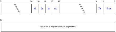
Fig. 13.1 Health Flag Bit Format
Health Flag Bit Field Description
explains the bit fields in the Health flag. IA-32 ignores all
bits except Tested (Te).
Field |
Parameter Name in |
Bit |
Description |
|---|---|---|---|
State |
|
0 1 |
A 2 bit field indicating self test state after reset For more information see Self-Test State Parameter |
Te |
|
2 |
A 1 bit field indicating whether testing has occurred If this field is zero the processor has not been tested and no further fields in the self test State parameter are valid |
Vm |
|
16 |
A 1 bit field If set to 1 indicates that virtual memory features are not available |
Ia |
|
17 |
A 1 bit field If set to 1 indicates that IA 32 execution is not available |
Fp |
|
18 |
A 1 bit field If set to 1 indicates that the floating point unit is not available |
Mf |
|
19 |
A 1 bit field If set to 1 indicates miscellaneous functional failure other than vm ia or fp The test status field provides additional information on test failures when the State field returns a value of performance restricted or functionally restricted The value returned is implementation dependent |
13.5.1. Self-Test State Parameter
Self-test state parameters are defined in the same format for IA-32 Intel® processors and the Intel® Itanium® processor family. Some of the test status bits may not be relevant to IA-32 processors. In that case, these bits will read NULL on IA-32 processors.
Self-Test State Bit Values indicates the meanings for various values of the self-test State parameter (bits 0:1) of the Health flag.
State |
Value |
Description |
|---|---|---|
Catastrophic Failure |
N/A |
Processor is not executing. |
Healthy |
00 |
No failure in functionality or performance. |
Performance Restricted |
01 |
No failure in functionality but performance is restricted. |
Functionally Restricted |
10 |
Some code may run but functionality is restricted and performance may also be affected. |
If the state field indicates that the processor is functionally restricted, then the vm, ia, and fp fields in the Health flag specify additional information about the functional failure. See Health Flag Bit Field Description for a description of these fields.
To further qualify “Functionally Restricted,” the following requirements will be met:
The processor or PAL (for the Itanium processor family) has detected and isolated the failing component so that it will not be used.
The processor must have at least one functioning memory unit, arithmetic logic unit (ALU), shifter, and branch unit.
The floating-point unit may be disabled.
For the Itanium processor family, the Register Stack Engine (RSE) is not required to work, but register renaming logic must work properly.
The paths between the processor-controlled caches and the register files must work during the tests.
Loads from the firmware address space must work correctly.
13.6. Processor-Specific Details
13.6.1. SEC Phase in IA-32 Intel Architecture
In 32-bit Intel® architecture (IA-32), the Security (SEC) phase of the PI Architecture is responsible for several activities:
Locating the PEI Foundation
Passing control directly to PEI using an architecturally defined handoff state
Initializing processor-controlled memory resources, such as the processor data cache, that can be used as a linear extent of memory for a call stack (if supported)
PEI Initialization Steps in IA-32 below shows the steps completed during PEI initialization for IA-32.
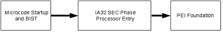
Fig. 13.2 PEI Initialization Steps in IA-32
13.6.2. SEC Phase in the Itanium Processor Family
Itanium architecture contains enough hooks to authenticate the PAL-A and PAL-B code distributed by the processor vendor.
The internal microcode on the processor silicon that starts up on a power-good reset finds the first layer of processor abstraction code (called PAL-A) located in the Boot Firmware Volume (BFV) using architecturally defined pointers in the BFV. It is the responsibility of this microcode to authenticate that the PAL-A code layer from the processor vendor has not been tampered.
If the authentication of the PAL-A layer passes, then control passes on to the PAL-A layer. The PAL-A layer then authenticates the next layer of processor abstraction code (called PAL-B) before passing control to it.
In addition, the SEC phase of the PI Architecture is also responsible for locating the PEI Foundation and verifying its authenticity.
Security (SEC) Phase in the Itanium ProcessorFamily summarizes the SEC phase in the Itanium® processor family.
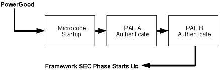
Fig. 13.3 Security (SEC) Phase in the Itanium ProcessorFamily