1. Overview
1.1. Definition of Terms
The following terms are used in the MM Core Interface Specification (CIS). See Glossary in the master help system for additional definitions.
- IP
Instruction pointer.
- IPI
Interprocessor Interrupt. This interrupt is the means by which multiple processors in a system or a single processor can issue APIC-directed messages for communicating with self or other processors.
- MM
Management Mode. Generic term for a secure, isolated execution environment entered when a CPU core detects an MMI and jumps to the MM Entry Point within MMRAM. This can be implemented by System Management Mode on x86 processors and TrustZone on ARM processors.
- MM Driver
A driver launched directly into MMRAM, with access to the MM interfaces.
- MM Driver Initialization
The phase of MM Driver initialization which starts with the call to the driver’s entry point and ends with the return from the driver’s entry point.
- MM Driver Runtime
The phase of MM Driver initialization which starts after the return from the driver’s entry point.
- MM Entry Point
When the CPU core(s) enter MM, they begin execution at a pre-defined addresses in a pre-defined operating mode. At some point later, they jump into the MM Foundation entry point.
- MM handler
A DXE driver that is loaded into and executed from MMRAM. MM Handlers are dispatched during boot services time and invoked synchronously or asynchronously thereafter. MM handlers remain present during runtime.
- MMI
Management Mode Invocation.The CPU instruction or high-priority interrupt which transitions CPU core(s) into MM via the MM Entry Point.
- MMI Source.
The instruction, interrupt or exception which caused the CPU core(s) to enter MM. An MMI source can be detected, quiesced and disabled.
- MMST
Management Mode System Table. Hand-off to handler.
- MTRR
Memory Type Range Register.
- RSM
Resume. The process by which a CPU exits MM.
1.2. Management Mode (MM)
Management Mode (MM) is a generic term used to describe a secure execution environment provided by the CPU and related silicon that is entered when the CPU detects a MMI. For x86 systems, this can be implemented with System Management Mode (SMM). For ARM systems, this can be implemented with TrustZone (TZ). A MMI can be a CPU instruction or interrupt. Upon detection of a MMI, a CPU will jump to the MM Entry Point and save some portion of its state (the “save state”) such that execution can be resumed. The MMI can be generated synchronously by software or asynchronously by a hardware event. Each MMI source can be detected, cleared and disabled. Some systems provide for special memory (Management Mode RAM or MMRAM) which is set aside for software running in MM. Usually the MMRAM is hidden during normal CPU execution, but this is not required. Usually, after MMRAM is hidden it cannot be exposed until the next system reset.
1.3. MM Driver Execution Environment
The MM Core Interface Specification describes the optional MM environment, which exists in parallel with the other PI Architecture phases into runtime. The MM Core Interface Specification describes three pieces of the PI Management Mode architecture:
- MM Dispatch
During DXE, the DXE Foundation works with the MM Foundation to schedule MM drivers for execution in the discovered firmware volumes.
- MM Initialization
MM related code opens MMRAM, creates the MMRAM memory map, and launches the MM Foundation, which provides the necessary services to launch MM-related drivers. Then, sometime before boot, MMRAM is closed and locked. This piece may be completed during the SEC, PEI or DXE phases.
- MMI Management
When an MMI generated, the MM environment is created and then the MMI sources are detected and MMI handlers called.
The figure below shows the MM architecture.
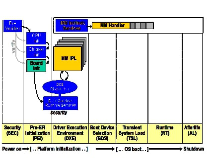
Fig. 1.1 MM Architecture
Note
The MM architecture does not guarantee support for the execution of handlers written to the EFI Byte Code (EBC) specification.
1.4. Initializing Management Mode in MM Traditional Mode
Management Mode initialization prepares the hardware for MMI generation and creates the necessary data structures for managing the MM resources such as MMRAM. This specification supports three MM initialization models: SEC, PEI and DXE. This specification does not describe MM Dispatch or MMI handling during SEC or PEI. Previous versions of this specification only supported DXE Initialization.
1.4.1. SEC Initialization
In this model, the MM Entry Points are initialized and the MM Foundation is loaded into MMRAM during the SEC phase. Optionally, MMRAM is hidden and locked. Then, during the DXE phase, MM or MM/DXE drivers are loaded normally. This is detailed in the following steps:
The SEC code initializes the MM environment, including initializing the MM Entry Points, setting up MMRAM, initializing the MM Foundation in MMRAM.
Optionally, the SEC code hides and locks the MMRAM.
The SEC code produces the EFI_SEC_HOB_DATA_PPI , which produces a HOB with the GUID EFI_PEI_MM_CORE_GUID , and the EFI_PEI_MM_CORE_LOADED flag set which indicates that the MM Foundation is already installed. After this, the steps follow those in DXE initialization. There is not architectural provision for loading MM-related drivers during the SEC phase.
1.4.2. PEI Initialization
In this model, the MM Entry Points are initialized and the MM Foundation is loaded into MMRAM during the PEI phase. Optionally, MMRAM is hidden and locked. Then, during the DXE phase, MM or MM/DXE drivers are loaded normally. This is detailed in the following steps:
The PEI code initializes the MM environment, including initializing the MM Entry Points, setting up MMRAM and initializing the MM Foundation in MMRAM.
Optionally, the PEI code hides and locks the MMRAM.
The PEI code produces the HOB with the GUID EFI_PEI_MM_CORE_GUID , and the EFI_PEI_MM_CORE_LOADED flag set, which indicates that the MM Foundation has already been installed. After this, the steps follow those in DXE initialization. There is not architectural provision for loading MM-related drivers during the PEI phase.
1.4.3. DXE Initialization
It is initialized with the cooperation of several DXE drivers:
A DXE driver produces the EFI_MM_ACCESS_PROTOCOL, which describes the different MMRAM regions available in the system.
A DXE driver produces the EFI_MM_CONTROL_PROTOCOL, which allows synchronous MMIs to be generated.
A DXE driver (dependent on the EFI_MM_ACCESS_PROTOCOL and, perhaps, the EFI_MM_CONTROL_PROTOCOL ), does the following:
If the MM_CORE_LOADED flag is not set in the EFI_PEI_MM_CORE_GUID HOB was not set, initializes the MM entry vector with the code necessary to meet the entry point requirements described in See Entering & Exiting MM..
If the MM_CORE_LOADED flag is not set in the EFI_PEI_MM_CORE_GUID HOB or that HOB does not exist, then produces the EFI_MM_CONFIGURATION _PROTOCOL , which describes those areas of MMRAM which should be excluded from the memory map.
NOTE: This implies that this DXE driver is completely optional if the MM_CORE_LOADED flag is set in the EFI_PEI_MM_CORE_GUID HOB.
The MM IPL DXE driver (dependent on the EFI_MM_CONTROL_PROTOCOL ) does the following:
If MM_CORE_LOADED flags is set in the EFI_PEI_MM_CORE_GUID HOB, register for notification of the installation of the EFI_MM_ACCESS_PROTOCOL and the EFI_MM_CONFIGURATION_PROTOCOL . Once both are available, opens MMRAM and:
Creates the MMRAM heap, excluding any areas listed in EFI_MM_CONFIGURATION_PROTOCOL MmramReservedRegions field.
Loads the MM Foundation into MMRAM. The MM Foundation produces the MMST.
Invokes the EFI_MM_CONFIGURATION_PROTOCOL.RegisterMmEntry() function with the MM Foundation entry point.
Publishes the EFI_MM_BASE_PROTOCOL in the UEFI Protocol Database
At this point MM is initially configured and MMIs can be generated.
Call the Communicate() member of the EFI_MM_COMMUNICATION_PROTOCOL with a buffer containing the EFI_MM_INITIALIAZATION_HEADER and the pointer to the UEFI System Table in the communication buffer. This gives the MM Core access to the UEFI Boot Services. Before this point, the MM Core must not use any UEFI services or protocols. NOTE: It also implies that the MM Core cannot find or dispatch any MM drivers from firmware volumes, since access to UEFI Boot Services is required to find instances for the Firmware Volume protocols.
Register for notification upon installation of the EFI_DXE_MM_READY_TO_LOCK_PROTOCOL in the UEFI protocol database.
During the remainder of the DXE phase, additional drivers may load and be initialized in MMRAM.
At some point prior to the processing of boot options, a DXE driver will install the EFI_DXE_MM_READY_TO_LOCK_PROTOCOL protocol in the UEFI protocol database. (outside of MM).
As a result, some DXE driver will cause the EFI_MM_READY_TO_LOCK_PROTOCOL protocol to be installed in the SM protocol database.
Optionally, close the MMRAM so that it is no longer visible using the EFI_MM_ACCESS_PROTOCOL . Closing MMRAM may not be supported on all platforms.
Optionally, lock the MMRAM so that its configuration can no longer be altered using the EFI_MM_ACCESS_PROTCOL . Locking MMRAM may not be supported on all platforms.
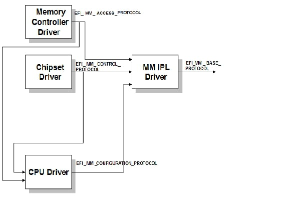
Fig. 1.2 Example MM Initialization Components
1.5. Initializing Management Mode in MM StandaloneMode
1.5.1. Initializing MM Standalone Mode in PEI phase
Management Mode initialization prepares the hardware for MMI generation and creates the necessary data structures for managing the MM resources such as MMRAM. It is initialized with the cooperation of several DXE driver or PEIMs. Details below:
A PEIM produces the EFI_PEI_MM_ACCESS_PPI , which describes the different MMRAM regions available in the system.
A PEIM produces the EFI_PEI_MM_CONTROL_PPI , which allows synchronous MMIs to be generated.
A PEIM (dependent on the EFI_PEI_MM_ACCESS_PPI and, perhaps, the EFI_PEI_MM_CONTROL_PPI ), does the following:
Initializes the MM entry vector with the code necessary to meet the entry point requirements described in Entering & Exiting MM.
Produces the EFI_MM_CONFIGURATION_PPI , which describes those areas of MMRAM which should be excluded from the memory map.
The MM IPL PEIM (dependent on the EFI_PEI_MM_ACCESS_PPI , EFI_PEI_MM_CONTROL_PPI and EFI_PEI_MM_CONFIGURATION_PPI ) does the following:
Opens MMRAM.
Creates the MMRAM heap, excluding any areas listed in EFI_PEI_MM_CONFIGURATION_PPI MmramReservedRegions field.
Loads the MM Foundation into MMRAM. The MM Foundation produces the MMST.
Invokes the EFI_PEI_MM_CONFIGURATION_PPI .RegisterMmEntry() function with the MM Foundation entry point.
At this point MM is initially configured and MMIs can be generated.
Publishes the EFI_PEI_MM_COMMUNICATION_PPI
During the remainder of the PEI phase, additional MM standalone drivers may load and be initialized in MMRAM.
During the remainder of the DXE phase, additional MM standalone drivers may load and be initialized in MMRAM.
A special MM IPL DXE driver does the following:
Communicate with MM Foundation and tell EFI_SYSTEM_TABLE pointer.
Publishes the EFI_MM_BASE_PROTOCOL in the UEFI Protocol Database
Publishes the EFI_MM_COMMUNICATION_PROTOCOL in the UEFI Protocol Database
During the remainder of the DXE phase, additional MM Traditional drivers may load and be initialized in MMRAM.
At some point prior to the processing of boot options, a DXE driver will install the EFI_DXE_MM_READY_TO_LOCK_PROTOCOL protocol in the UEFI protocol database. (outside of MM).
As a result, some DXE driver will cause the EFI_MM_READY_TO_LOCK_PROTOCOL protocol to be installed in the MM protocol database.
Optionally, close the MMRAM so that it is no longer visible using the EFI_MM_ACCESS_PROTOCOL . Closing MMRAM may not be supported on all platforms.
Optionally, lock the MMRAM so that its configuration can no longer be altered using the EFI_MM_ACCESS_PROTCOL . Locking MMRAM may not be supported on all platforms.
Note
In order to support both MM standalone driver and MM traditional driver, the MM Foundation must have same calling convention as DXE phase, instead of PEI phase. It means, if PEI phase is 32bit, DXE phase is 64bit, then the MM Foundation must be 64bit. The 32bit MM IPL PEIM must have ability to launch 64bit MM Foundation.
1.5.2. Initializing MM Standalone Mode in SEC phase
Standalone Mode can also be initialized in SEC phase. We take SEC phase initialization as example for MM Standalone Mode, as described below:
SEC does the following:
Initializes the MM entry vector with the code necessary to meet the entry point requirements described in Entering & Exiting MM.
Opens MMRAM.
Creates the MMRAM heap.
Loads the MM Foundation into MMRAM. The MM Foundation produces the MMST.
Invokes the RegisterMmEntry() function with the MM Foundation entry point.
At this point MM is initially configured and MMIs can be generated.
Optionally, closes MMRAM so that it is no longer visible.
Optionally, locks MMRAM so that its configuration can no longer be altered.
Then SEC Core can load PEI core as normal process.
A special MM IPL PEIM does the following:
Publishes the EFI_PEI_MM_COMMUNICATION_PPI
During the remainder of the PEI phase, additional MM standalone drivers may load and be initialized in MMRAM.
During the remainder of the DXE phase, additional MM standalone drivers may load and be initialized in MMRAM.
A special MM IPL DXE driver does the following:
Communicate with MM Foundation and tell EFI_SYSTEM_TABLE pointer.
Publishes the EFI_MM_BASE_PROTOCOL in the UEFI Protocol Database
Publishes the EFI_MM_COMMUNICATION_PROTOCOL in the UEFI Protocol Database
During the remainder of the DXE phase, additional MM traditional drivers may load and be initialized in MMRAM.
At some point prior to the processing of boot options, a DXE driver will install the EFI_DXE_MM_READY_TO_LOCK_PROTOCOL protocol in the UEFI protocol database. (outside of MM).
As a result, some DXE driver will cause the EFI_MM_READY_TO_LOCK_PROTOCOL protocol to be installed in the MM protocol database.
Note
In order to support both MM standalone driver and MM traditional driver, the MM Foundation must have same calling convention as DXE phase, instead of SEC phase. This means that if the SEC phase is 32bit, DXE phase is 64bit, then the MM Foundation must be 64bit. The 32bit SEC must have ability to launch 64bit MM Foundation.
1.6. Entering & Exiting MM
The code at the entry vector must:
Save any CPU state necessary for supporting the EFI_MM_CPU_PROTOCOL
Save any CPU state so that the normal operation can be resumed.
Select a single CPU to enter the MM Foundation.
If an entry point has been registered via RegisterMmEntry() , switch to the same CPU mode as the MM Foundation and call the MM Foundation entry point.
The MM Foundation entry point must:
Update the MMST with the CPU information passed to the entry point.
Call all root MMI controller handlers using MmiManage (NULL)
Return to the entry vector code.
After returning from the MM Foundation entry point, the code at the entry vector must:
Restore any CPU state information necessary for normal operation.
Resume normal operation
1.7. MM Traditional Drivers
There are two types of SM-related drivers: MM Drivers and Combination SM/DXE Drivers. Both types of drivers are initialized by calling their main entry point. The entry point of the driver is the same as a UEFI Specification EFI_IMAGE_ENTRY_POINT .
1.7.1. MM Drivers
MM Drivers must have the file type EFI_FV_FILETYPE_MM . MM Drivers are launched once, directly into MMRAM in MM Traditional Mode. MM Drivers cannot be launched until the dependency expression in the file section EFI_SECTION_MM_DEPEX evaluates to true. This dependency expression can refer to both UEFI and SM protocols. The entry point of the driver is the same as a UEFI Specification EFI_IMAGE_ENTRY_POINT .
1.7.2. Combination MM/DXE Drivers
Combination MM/DXE Drivers must have the file type EFI_FV_FILETYPE_COMBINED_MM_DXE . Combination Drivers are launched twice.
They are launched by the DXE Dispatcher as a normal DXE driver outside of MMRAM in MM Tradtional Mode after the dependency expression in the file section EFI_SECTION_DXE_DEPEX evaluates to true. As DXE Drivers, they have access to the normal UEFI interfaces.
Combination Drivers are also launched as MM Drivers inside of MMRAM after the dependency expression in the file section EFI_SECTION_MM_DEPEX evaluates to true.
Combination Drivers have access to DXE, UEFI and SM services during MM Initialization. Combination Drivers have access to MM services during MM Runtime.
Combination Drivers can determine whether or not they are executing during MM Initialization or MM Runtime by locating the EFI_MM_READY_TO_LOCK_MM_PROTOCOL .
On the first load, the entry point of the driver is the same as a UEFI specification EFI_IMAGE_ENTRY_POINT since the driver is loaded by the DXE core.
On the second load, the entry point of the driver is the same as a UEFI Specification EFI_IMAGE_ENTRY_POINT .
1.7.3. MM Standalone Drivers
MM Standalone Drivers must have the file type EFI_FV_FILETYPE_MM_STANDALONE . MM Standalone Drivers are launched once, directly into MMRAM. MM Standalone Drivers cannot be launched until the dependency expression in the file section EFI_SECTION_MM_DEPEX evaluates to true. This dependency expression must refer to MM protocols.
The entry point of the driver is defined below as MM_IMAGE_ENTRY_POINT .
1.7.4. MM_IMAGE_ENTRY_POINT
This function is the main entry point to an MM Standalone Driver.
Prototype
typedef
VOID
(EFIAPI \*MM_IMAGE_ENTRY_POINT) (
IN EFI_HANDLE                       *ImageHandle* ,
IN EFI_MM_SYSTEM_TABLE              *MmSystemTable*
);
Parameters
ImageHandle
The handle allocated for the MMStandalone Driver.
MmSystemTable
A pointer to the MM System Table.
Description
This function is the entry point to an MM Standalone Driver. An MM Standalone Driver is loaded and relocated into MMRAM by* MM Foundation . The first argument is the image’s image handle. The second argument is a pointer to the MM system table.
1.7.5. SOR and Dependency Expressions for SM
The Apriori file can also contain DXE and SM FFS files. The implementation doesn’t support SOR for the MM drivers, though.
1.8. MM Traditional Driver Initialization
An MM Driver’s initialization phase begins when the driver has been loaded into MMRAM in MM Traditional Mode and its entry point is called. An MM Driver’s initialization phase ends when the entry point returns.
During MM Driver initialization, MM Drivers have access to two sets of protocols: UEFI and SM. UEFI protocols are those which are installed and discovered using the UEFI Boot Services. UEFI protocols can be located and used by MM drivers only during MM Initialization. SM protocols are those which are installed and discovered using the Management Mode Services Table (MMST). SM protocols can be discovered by MM drivers during initialization time and accessed while inside of SM.
MM Drivers shall not use the following UEFI Boot Services during MM Driver Initialization:
Exit()
ExitBootServices()
1.9. MM Standalone Driver Initialization
An MM Standalone Driver’s initialization phase begins when the driver has been loaded into MMRAM in MM Standalone Mode and its entry point is called. An MM Standalone Driver’s initialization phase ends when the entry point returns.
During MM Standalone Driver initialization, MM Standalone Drivers can only access MM protocols. MM protocols are those which are installed and discovered using the Management Mode Services Table (MMST). MM protocols can be discovered by MM Drivers during initialization time and accessed while inside of MM.
1.10. MM Traditional Driver Runtime
During MM Driver runtime, MM Drivers only have access to MM protocols. In addition, depending on the platform architecture, memory areas outside of MMRAM may not be accessible to MM Drivers. Likewise, memory areas inside of MMRAM may not be accessible to UEFI drivers.
These MM Driver Runtime characteristics lead to several restrictions regarding the usage of UEFI services:
UEFI interfaces and services which are located during MM Driver Initialization should not be called or referenced during MM Driver Runtime. This includes the EFI System Table, the UEFI Boot Services and the UEFI Runtime Services.
Installed UEFI protocols should be uninstalled before exiting the driver entry point, or the UEFI protocol should refer to addresses which are not within MMRAM.
Events created during MM Driver Initialization should be closed before exiting the drier entry point.
1.11. MM Standalone Driver Runtime
During MM Standalone Driver runtime, MM drivers only have access to MM protocols. In addition, depending on the platform architecture, memory areas outside of MMRAM may not be accessible to MM Drivers.
1.12. Dispatching MMI Handlers
MMI handlers are registered using the MMST’s MmiHandlerRegister() function. MMI handlers fall into three categories:
- RootMMI Controller Handlers
These are handlers for devices which directly control MMI generation for the CPU(s). The handlers have the ability to detect, clear and disable one or more MMI sources. They are registered by calling MmiHandlerRegister() with HandlerType set to NULL. After an MMI source has been detected, the Root MMI handler calls the Child MMI Controllers or MMI Handlers whose handler functions were registered using either an MM Child Dispatch protocols or using MmiHandlerRegister() . To call the latter, it calls Manage() with a GUID identifying the MMI source so that any registered Child MMI Handlers or Leaf MMI Handlers will be called. If the handler returns EFI_INTERRUPT_PENDING , it indicates that the interrupt source could not be quiesced. If possible, the Root MMI handler should disable and clear the MMI source. If the handler does not return an error, the Root MMI Handler should clear the MMI source.
- Child MMI Controller Handlers
These are MMI handlers which handle a single interrupt source from a Root or Child MMI handler and, in turn, control one or more child MMI sources which can be detected, cleared and disabled. They are registered by calling the MmiHandlerRegister() function with HandlerType set to the GUID of the Parent MMI Controller MMI source. Handlers for this MMI handler’s MMI sources are called in the same manner as Root MMI Handlers.
- MMI Handlers
These MMI handlers perform basic software or hardware services based on the MMI source received. If the MMI handler manages a device outside the control of the Parent MMI Controller, it must make sure that the device is quiesced, especially if the device drives a level-active input.
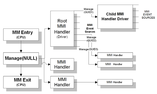
Fig. 1.3 MMI Handler Relationships
1.13. MM Services
1.13.1. MM Driver Model
The MM Driver model has similar constraints to those of UEFI runtime drivers. Specifically, during MM Driver Runtime, the drivers must not use core protocol services. There will be MMST-based services, which the drivers can access, but the UEFI System Table and other protocols installed during boot services are not available.
Instead, the full collection of UEFI Boot Services and UEFI Runtime Services are available only during the MM Driver Initialization phase. This visibility is useful so that the MM Driver can leverage the rich set of UEFI services. This design makes the UEFI protocol database useful to these drivers while outside of SM and during their initial load within SM.
The MMST-based services that are available include the following:
A minimal, blocking variant of the device I/O protocol
A memory allocator from MM memory
A minimal protocol database for protocols for use inside of SM.
These services are exposed by entries in the Management Mode System Table (MMST) .
1.13.2. MM Protocols
Additional standard protocols are exposed as SM protocols and accessed using the protocol services provided by the MMST. They may be located during MM Driver Initialization or MM Driver Runtime. MM Driver. For example, the status code equivalent in MM is simply a UEFI protocol whose interface references an MM-based driver’s service. Other MM Drivers locate this MM-based status code protocol and can use it during runtime to emit error or progress information.
1.14. MM UEFI Protocols
This section describes those protocols related to MM that are available through the UEFI boot services (called “UEFI Protocols”) or through the MMST (called “MM Protocols”).
1.14.1. UEFI Protocols
The system architecture of the MM driver is broken into the following pieces:
MM Base Protocol
MM Access Protocol
MM Control Protocol
The MM Base Protocol will be published by the MM IPL driver which activates the MM Foundation for usage during the DXE phase.The MM Access Protocol understands the particular enable and locking mechanisms that memory controller might support while executing in MM.
The MM Control Protocol understands how to trigger synchronous MMIs either once or periodically.
1.14.2. MM Protocols
The following figure shows the MM protocols that are published for an IA-32 system.
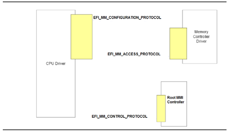
Fig. 1.4 Published Protocols for IA-32 Systems