2. Firmware Storage Design Discussion
2.1. Firmware Storage Introduction
This specification describes how files should be stored and accessed within non-volatile storage. Firmware implementations must support the standard PI Firmware Volume and Firmware File System format (described below), but may support additional storage formats.
2.1.1. Firmware Devices
A firmware device is a persistent physical repository that contains firmware code and/or data. It is typically a flash component but may be some other type of persistent storage. A single physical firmware device may be divided into smaller pieces to form multiple logical firmware devices. Similarly, multiple physical firmware devices may be aggregated into one larger logical firmware device.
This section describes the characteristics of typical physical firmware devices.
2.1.1.1. Flash
Flash devices are the most common non-volatile repository for firmware volumes. Flash devices are often divided into sectors (or blocks) of possibly differing sizes, each with different run-time characteristics. Flash devices have several unique qualities that are reflected in the design of the firmware file system:
Flash devices can be erased on a sector-by-sector basis. After an erasure, all bits within a sector return to their erase value, either all 0 or all 1.
Flash devices can be written on a bit-by-bit basis if the change is from its erase value to the non-erase value. For example, if the erase value is 1, then a bit with the value 1 can be changed to 0.
Flash devices can only change from a non-erase value to an erase value by performing an erase operation on an entire flash sector.
Some flash devices can enable or disable reads and writes to the entire flash device or to individual flash sectors.
Some flash devices can lock the current enable or disable state of reads and writes until the next reset.
Flash writes and erases are often longer operations than reads.
Flash devices often place restrictions on the operations that can be performed while a write or erase is occurring.
2.1.2. Firmware Volumes
A Firmware Volume (FV) is a logical firmware device. In this specification, the basic storage repository for data and/or code is the firmware volume. Each firmware volume is organized into a file system. As such, the file is the base unit of storage for firmware.
Each firmware volume has the following attributes:
Name. Each volume has a name consisting of an UEFI Globally Unique Identifier (GUID).
Size. Each volume has a size, which describes the total size of all volume data, including any header, files, and free space.
Format. Each volume has a format, which describes the Firmware File System used in the body of the volume.
Memory Mapped? Some volumes may be memory-mapped, which indicates that the entire contents of the volume appear at once in the memory address space of the processor.
Sticky Write? Some volumes may require special erase cycles in order to change bits from a non-erase value to an erase value.
Erase Polarity. If a volume supports “Sticky Write,” then all bits within the volume will return to this value (0 or 1) after an erase cycle.
Alignment. The first byte of a volume is required to be aligned on some power-of-two boundary. At a minimum, this must be greater than or equal to the highest file alignment value. If
EFI_FVB2_WEAK_ALIGNMENTis set in the volume header then the first byte of the volume can be aligned on any power-of-two boundary. A weakly aligned volume can not be moved from its initial linked location and maintain its alignment.Read Enable/Disable Capable/Status. Volumes may have the ability to change from readable to hidden.
Write Enable/Disable Capable/Status. Volumes may have the ability to change from writable to write protected.
Lock Capable/Status. Volumes may be able to have their capabilities locked.
Read-Lock Capable/Status. Volumes may have the ability to lock their read status.
Write-Lock Capable/Status. Volumes may have the ability to lock their write status.
Firmware volumes may also contain additional information describing the mapping between OEM file types and a GUID.
2.1.3. Firmware File System
A firmware file system (FFS) describes the organization of files and (optionally) free space within the firmware volume. Each firmware file system has a unique GUID, which is used by the firmware to associate a driver with a newly exposed firmware volume.
The PI Firmware File System is described in Firmware File System Format.
2.1.4. Firmware Files
Firmware files are code and/or data stored in firmware volumes. Each of the files has the following attributes:
Name. Each file has a name consisting of an UEFI GUID. File names must be unique within a firmware volume. Some file names have special significance.
Type. Each file has a type. There are four ranges of file types: Normal (0x00-0xBF), OEM (0xC0-0xDF), Debug (0xE0-0xEF) and Firmware Volume Specific (0xF0-0xFF). For more information on types, see Firmware File Types.
Alignment. Each file’s data can be aligned on some power-of-two boundary. The specific boundaries that are supported depend on the alignment and format of the firmware volume. If
EFI_FVB2_WEAK_ALIGNMENTis set in the volume header then file alignment does not depend on volume alignment.Size. Each file’s data is zero or more bytes.
Specific firmware volume formats may support additional attributes, such as integrity verification and staged file creation. The file data of certain file types is sub-divided in a standardized fashion into Firmware File Sections.
Non-standard file types are supported through the use of the OEM file types. See Firmware File Types for more information.
In the PEI phase, file-related services are provided through
the PEI Services Table, using FfsFindNextFile ,
FfsFindFileByName and FfsGetFileInfo . In the DXE phase,
file-related services are provided through the
EFI_FIRMWARE_VOLUME2_PROTOCOL services attached to a volume’s
handle ( ReadFile , ReadSection , WriteFile and
GetNextFile ).
2.1.4.1. Firmware File Types
Consider an application file named FOO.EXE. The format of the contents of FOO.EXE is implied by the “.EXE” in the file name. Depending on the operating environment, this extension typically indicates that the contents of FOO.EXE are a PE/COFF image and follow the PE/COFF image format.
Similarly, the PI Firmware File System defines the contents of a file that is returned by the firmware volume interface.
The PI Firmware File System defines an enumeration of file
types. For example, the type EFI_FV_FILETYPE_DRIVER
indicates that the file is a DXE driver and is interesting
to the DXE Dispatcher. In the same way, files with the type
EFI_FV_FILETYPE_PEIM are interesting to the PEI
Dispatcher.
Name |
Value |
Description |
|---|---|---|
|
0x01 |
Binary data |
|
0x02 |
Sectioned data |
|
0x03 |
Platform core code used during the SEC phase |
|
0x04 |
PEI Foundation |
|
0x05 |
DXE Foundation |
|
0x06 |
PEI module PEIM |
|
0x07 |
DXE driver |
|
0x08 |
Combined PEIM DXE driver |
|
0x09 |
Application |
|
0x0A |
Contains a PE32 image that will be loaded into MMRAM in MM Traditional Mode |
|
0x0B |
Firmware volume image |
|
0x0C |
Contains PE32 image that will be dispatched by the DXE Dispatcher and will also be loaded into MMRAM in MM Tradition Mode |
|
0x0D |
MM Foundation that support MM Traditional Mode |
|
0x0E |
Contains a PE32 image that will be loaded into MMRAM in MM Standalone Mode |
|
0x0F |
MM Foundation that support MM Tradition Mode and MM Standalone Mode |
|
0xC0 0xDF |
OEM File Types |
|
0xE0 0xEF |
Debug Test File Types |
|
0xF0 0xFF |
Firmware File System Specific File Types |
|
0xF0 |
Pad File For FFS |
2.1.4.1.1. EFI_FV_FILETYPE_APPLICATION
The file type EFI_FV_FILETYPE_APPLICATION denotes a
file that contains a PE32 image that can be loaded using
the UEFI Boot Service LoadImage() . Files of type
EFI_FV_FILETYPE_APPLICATION are not dispatched by the
DXE Dispatcher.
This file type is a sectioned file that must be constructed in accordance with the following rule:
The file must contain at least one
EFI_SECTION_PE32section. There are no restrictions on encapsulation of this section.
There are no restrictions on the encapsulation of the leaf section.
In the event that more than one EFI_SECTION_PE32
section is present in the file, the selection algorithm
for choosing which one represents the PE32 for the
application in question is defined by the LoadImage()
boot service. See the Platform Initialization Driver
Execution Environment Core Interface Specification for
details.
The file may contain other leaf and encapsulation sections as required or enabled by the platform design.
2.1.4.1.2. EFI_FV_FILETYPE_COMBINED_PEIM_DRIVER
The file type EFI_FV_FILETYPE_COMBINED_PEIM_DRIVER
denotes a file that contains code suitable for dispatch
by the PEI Dispatcher, as well as a PE32 image that can
be dispatched by the DXE Dispatcher. It has two uses:
Enables sharing code between PEI and DXE to reduce firmware storage requirements.
Enables bundling coupled PEIM/driver pairs in the same file.
This file type is a sectioned file and must follow the
intersection of all rules defined for both
EFI_FV_FILETYPE_PEIM and EFI_FV_FILETYPE_DRIVER
files. This intersection is listed below:
The file must contain one and only one
EFI_SECTION_PE32section. There are no restrictions on encapsulation of this section; however, care must be taken to ensure any execute-in-place requirements are satisfied.The file must not contain more than one
EFI_SECTION_DXE_DEPEXsection.The file must not contain more than one
EFI_SECTION_PEI_DEPEXsection.The file must contain no more than one
EFI_SECTION_VERSIONsection.
The file may contain other leaf and encapsulation sections as required or enabled by the platform design.
2.1.4.1.3. EFI_FV_FILETYPE_COMBINED_SMM_DXE
The file type EFI_FV_FILETYPE_COMBINED_MM_DXE denotes a
file that contains a PE32+ image that will be dispatched
by the DXE Dispatcher and will also be loaded into MMRAM
in MM Traditional Mode.
This file type is a sectioned file that must be constructed in accordance with the following rules:
The file must contain at least one
EFI_SECTION_PE32section. There are no restrictions on encapsulation of this section.The file must contain no more than one
EFI_SECTION_VERSIONsection.The file must contain no more than one
EFI_SECTION_DXE_DEPEXsection. This section is ignored when the file is loaded into SMRAM.The file must contain no more than one
EFI_SECTION_MM_DEPEXsection. This section is ignored when the file is dispatched by the DXE Dispatcher.
There are no restrictions on the encapsulation of the
leaf sections. In the event that more than one
EFI_SECTION_PE32 section is present in the file, the
selection algorithm for choosing which one represents the
DXE driver that will be dispatched is defined by the
LoadImage() boot service, which is used by the DXE
Dispatcher. See the Platform Initialization
Specification, Volume 2 for details. The file may contain
other leaf and encapsulation sections as required or
enabled by the platform design.
2.1.4.1.4. EFI_FV_FILETYPE_DRIVER
The file type EFI_FV_FILETYPE_DRIVER denotes a file
that contains a PE32 image that can be dispatched by the
DXE Dispatcher.
This file type is a sectioned file that must be constructed in accordance with the following rules:
The file must contain at least one
EFI_SECTION_PE32section. There are no restrictions on encapsulation of this section.The file must contain no more than one
EFI_SECTION_VERSIONsection.The file must contain no more than one
EFI_SECTION_DXE_DEPEXsection.
There are no restrictions on the encapsulation of the leaf sections.
In the event that more than one EFI_SECTION_PE32
section is present in the file, the selection algorithm
for choosing which one represents the DXE driver that
will be dispatched is defined by the LoadImage() boot
service, which is used by the DXE Dispatcher. See the
Platform Initialization Driver Execution Environment
Core Interface Specification for details.
The file may contain other leaf and encapsulation sections as required or enabled by the platform design.
2.1.4.1.5. EFI_FV_FILETYPE_DXE_CORE
The file type EFI_FV_FILETYPE_DXE_CORE denotes the DXE
Foundation file. This image is the one entered upon
completion of the PEI phase of a UEFI boot cycle.
This file type is a sectioned file that must be constructed in accordance with the following rules:
The file must contain at least one and only one executable section, which must have a type of
EFI_SECTION_PE32.The file must contain no more than one
EFI_SECTION_VERSIONsection.
The sections that are described in the rules above may be optionally encapsulated in compression and/or additional GUIDed sections as required by the platform design.
As long as the above rules are followed, the file may contain other leaf and encapsulation sections as required or enabled by the platform design.
2.1.4.1.6. EFI_FV_FILETYPE_FIRMWARE_VOLUME_IMAGE
The file type EFI_FV_FILETYPE_FIRMWARE_VOLUME_IMAGE
denotes a file that contains one or more firmware volume
images.
This file type is a sectioned file that must be constructed in accordance with the following rule:
The file must contain at least one section of type
EFI_SECTION_FIRMWARE_VOLUME_IMAGE. There are no restrictions on encapsulation of this section.
The file may contain other leaf and encapsulation sections as required or enabled by the platform design.
2.1.4.1.7. EFI_FV_FILETYPE_FREEFORM
The file type EFI_FV_FILETYPE_FREEFORM denotes a
sectioned file that may contain any combination of
encapsulation and leaf sections. While the section layout
can be parsed, the consumer of this type of file must
have a priori knowledge of how it is to be used.
Standard firmware file system services will not return
the handle of any pad files, nor will they permit
explicit creation of such files. The Name field of the
EFI_FFS_FILE_HEADER and EFI_FFS_FILE_HEADER2
structures is considered invalid for pad files and will
not be used in any operation that requires name
comparisons.
A single EFI_SECTION_FREEFORM_SUBTYPE_GUID section may
be included in a file of type EFI_FV_FILETYPE_FREEFORM
to provide additional file type differentiation. While it
is permissible to omit the
EFI_SECTION_FREEFORM_SUBTYPE_GUID section entirely,
there must never be more than one instance of it.
2.1.4.1.8. EFI_FV_FILETYPE_FFS_PAD
A pad file is an FFS-defined file type that is used to
pad the location of the file that follows it in the
storage file. The normal state of any valid (not deleted
or invalidated) file is that both its header and data are
valid. This status is indicated using the State bits
with State = 00000111b . Pad files differ from all
other types of files in that any pad file in this state
must not have any data written into the data space. It is
essentially a file filled with free space.
Standard firmware file system services will not return
the handle of any pad files, nor will they permit
explicit creation of such files. The Name field of the
EFI_FFS_FILE_HEADER structure is considered invalid for
pad files and will not be used in any operation that
requires name comparisons.
2.1.4.1.9. EFI_FV_FILETYPE_PEIM
The file type EFI_FV_FILETYPE_PEIM denotes a file that
is a PEI module (PEIM). A PEI module is dispatched by the
PEI Foundation based on its dependencies during execution
of the PEI phase. See the Platform Initialization Pre-EFI
Initialization Core Interface Specification for details
on PEI operation.
This file type is a sectioned file that must be constructed in accordance with the following rules:
The file must contain one and only one executable section. This section must have one of the following types:
EFI_SECTION_PE32
EFI_SECTION_PIC
EFI_SECTION_TE
The file must contain no more than one
EFI_SECTION_VERSIONsection.The file must contain no more than one
EFI_SECTION_PEI_DEPEXsection.
As long as the above rules are followed, the file may contain other leaf and encapsulation sections as required or enabled by the platform design. Care must be taken to ensure that additional encapsulations do not render the file inaccessible due to execute-in-place requirements.
2.1.4.1.10. EFI_FV_FILETYPE_PEI_CORE
The file type EFI_FV_FILETYPE_PEI_CORE denotes the PEI
Foundation file. This image is entered upon completion of
the SEC phase of a PI Architecture-compliant boot cycle.
This file type is a sectioned file that must be constructed in accordance with the following rules:
The file must contain one and only one executable section. This section must have one of the following types:
EFI_SECTION_PE32
EFI_SECTION_PIC
EFI_SECTION_TE
The file must contain no more than one
EFI_SECTION_VERSIONsection.
As long as the above rules are followed, the file may contain other leaf and encapsulations as required/enabled by the platform design.
2.1.4.1.11. EFI_FV_FILETYPE_RAW
The file type EFI_FV_FILETYPE_RAW denotes a file that
does not contain sections and is treated as a raw data
file. The consumer of this type of file must have a
priori knowledge of its format and content. Because there
are no sections, there are no construction rules.
2.1.4.1.12. EFI_FV_FILETYPE_SECURITY_CODE
The file type EFI_FV_FILETYPE_SECURITY_CORE denotes
code and data that comprise the first part of PI
Architecture firmware to execute. Its format is undefined
with respect to the PI Architecture, as differing
platform architectures may have varied requirements.
2.1.4.1.13. EFI_FV_FILETYPE_MM
The file type EFI_FV_FILETYPE_MM denotes a file that
contains a PE32+ image that will be loaded into MMRAM in
MM Tradition Mode.
This file type is a sectioned file that must be constructed in accordance with the following rules:
The file must contain at least one
EFI_SECTION_PE32section. There are no restrictions on encapsulation of this section.The file must contain no more than one
EFI_SECTION_VERSIONsection.The file must contain no more than one
EFI_SECTION_MM_DEPEXsection.
There are no restrictions on the encapsulation of the
leaf sections. In the event that more than one
EFI_SECTION_PE32 section is present in the file, the
selection algorithm for choosing which one represents the
DXE driver that will be dispatched is defined by the
LoadImage() boot service, which is used by the DXE
Dispatcher. See the Platform Initialization
Specification, Volume 2 for details. The file may contain
other leaf and encapsulation sections as required or
enabled by the platform design.
2.1.4.1.14. EFI_FV_FILETYPE_MM_CORE
The file type EFI_FV_FILETYPE_MM_CORE denotes the MM
Foundation file that only supports MM Traditional Mode.
This image will be loaded by MM IPL into MMRAM.
This file type is a sectioned file that must be constructed in accordance with the following rules:
The file must contain at least one and only one executable section, which must have a type of
EFI_SECTION_PE32.The file must contain no more than one
EFI_SECTION_VERSIONsection.
The sections that are described in the rules above may be optionally encapsulated in compression and/or additional GUIDed sections as required by the platform design.
As long as the above rules are followed, the file may contain other leaf and encapsulation sections as required or enabled by the platform design.
2.1.4.1.15. EFI_FV_FILETYPE_MM_STANDALONE
The file type EFI_FV_FILETYPE_MM_STANDALONE denotes a
file that contains a PE32+ image that will be loaded into
SMRAM in SMM Standalone Mode.
This file type is a sectioned file that must be constructed in accordance with the following rules:
The file must contain at least one
EFI_SECTION_PE32section. There are no restrictions on encapsulation of this section.The file must contain no more than one
EFI_SECTION_VERSIONsection.The file must contain no more than one
EFI_SECTION_MM_DEPEXsection.
There are no restrictions on the encapsulation of the
leaf sections. In the event that more than one
EFI_SECTION_PE32 section is present in the file, the
selection algorithm for choosing which one represents the
MM driver that will be dispatched is defined by MM
Foundation Dispatcher. See the Platform Initialization
Specification, Volume 4 for details. The file may
contain other leaf and encapsulation sections as required
or enabled by the platform design.
2.1.4.1.16. EFI_FV_FILETYPE_MM_CORE_STANDALONE
The file type EFI_FV_FILETYPE_SMM_CORE_STANDALONE
denotes the MM Foundation file that support MM
Traditional Mode and MM Standalone Mode. This image will
be loaded by standalone MM IPL into MMRAM.
2.1.5. Firmware File Sections
Firmware file sections are separate discrete “parts” within certain file types. Each section has the following attributes:
Type. Each section has a type. For more information on section types, see Firmware File Section Types.
Size. Each section has a size.
While there are many types of sections, they fall into the following two broad categories:
Encapsulation sections
Leaf sections
Encapsulation sections are essentially containers that hold other sections. The sections contained within an encapsulation section are known as child sections, and the encapsulation section is known as the parent section. Encapsulation sections may have many children. An encapsulation section’s children may be leaves and/or more encapsulation sections and are called peers relative to each other. An encapsulation section does not contain data directly; instead it is just a vessel that ultimately terminates in leaf sections.
Files that are built with sections can be thought of as a tree, with encapsulation sections as nodes and leaf sections as the leaves. The file image itself can be thought of as the root and may contain an arbitrary number of sections. Sections that exist in the root have no parent section but are still considered peers.
Unlike encapsulation sections, leaf sections directly contain data and do not contain other sections. The format of the data contained within a leaf section is defined by the type of the section.
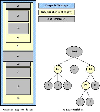
Fig. 2.3 Example File Image (Graphical and TreeRepresentations)
In the example shown in Example File Image (Graphical and TreeRepresentations), the
file image root contains two encapsulation sections (E0 and E1)
and one leaf section (L3). The first encapsulation section (E0)
contains children, all of which are leaves (L0, L1, and L2).
The second encapsulation section (E1) contains two children,
one that is an encapsulation (E2) and the other that is a leaf
(L6). The last encapsulation section (E2) has two children that
are both leaves (L4 and L5)
In the PEI phase, section-related services are provided through
the PEI Service Table, using FfsFindSectionData . In the DXE
phase, section-related services are provided through the
EFI_FIRMWARE_VOLUME2_PROTOCOL services attached to a volume’s
handle (ReadSection).
2.1.5.1. Firmware File Section Types
Architectural Section Types lists the defined architectural section types.
Name |
Value |
Description |
|---|---|---|
|
0x01 |
Encapsulation section where other sections are compressed |
|
0x02 |
Encapsulation section where other sections have format defined by a GUID |
|
0x03 |
Encapsulation section used during the build process but not required for execution |
|
0x10 |
PE32 Executable image |
|
0x11 |
Position Independent Code |
|
0x12 |
Terse Executable image |
|
0x13 |
DXE Dependency Expression |
|
0x14 |
Version Text and Numeric |
|
0x15 |
User Friendly name of the driver |
|
0x16 |
DOS style 16 bit EXE |
|
0x17 |
PI Firmware Volume image |
|
0x18 |
Raw data with GUID in header to define format |
|
0x19 |
Raw data |
|
0x1b |
PEI Dependency Expression |
|
0x1c |
Leaf section type for determining the dispatch order for an MM Traditional driver in MM Traditional Mode or MM Standaline driver in MM Standalone Mode |
2.2. PI Architecture Firmware File System Format
This section describes the standard binary encoding for PI Firmware Files, PI Firmware Volumes, and the PI Firmware File System. Implementations that allow the non-vendor firmware files or firmware volumes to be introduced into the system must support the standard formats. This section also describes how features of the standard format map into the standard PEI and DXE interfaces.
The standard firmware file and volume format also introduces additional attributes and capabilities that are used to guarantee the integrity of the firmware volume. The standard format is broken into three levels: the firmware volume format, the firmware file system format, and the firmware file format.
The standard firmware volume format (The Firmware Volume Format) consists of two parts: the firmware volume header and the firmware volume data. The firmware volume header describes all of the attributes specified in Firmware Volumes. The header also contains a GUID which describes the format of the firmware file system used to organize the firmware volume data. The firmware volume header can support other firmware file systems other than the PI Firmware File System.
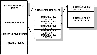
Fig. 2.4 The Firmware Volume Format
The PI Firmware File System format describes how firmware files and free space are organized within the firmware volume.
The PI Firmware File format describes how files are organized. The firmware file format consists of two parts: the firmware file header and the firmware file data.
2.2.1. Firmware Volume Format
The PI Architecture Firmware Volume format describes the binary
layout of a firmware volume. The firmware volume format
consists of a header followed by the firmware volume data. The
firmware volume header is described by
EFI_FIRMWARE_VOLUME_HEADER.
The format of the firmware volume data is described by a GUID.
Valid files system GUID values are
EFI_FIRMWARE_FILE_SYSTEM2_GUID and
EFI_FIRMWARE_FILE_SYSTEM3_GUID.
2.2.2. Firmware File System Format
The PI Architecture Firmware File System is a binary layout of file storage within firmware volumes. It is a flat file system in that there is no provision for any directory hierarchy; all files reside in the root directly. Files are stored end to end without any directory entry to describe which files are present. Parsing the contents of a firmware volume to obtain a listing of files present requires walking the firmware volume from beginning to end.
All files stored with the FFS must follow the PI Architecture Firmware File System Format. The standard file header provides for several levels of integrity checking to help detect file corruption, should it occur for some reason. This section describes:
PI Architecture’s Firmware File System GUID (s)
Volume Top File (VTF)
2.2.2.1. Firmware File System GUID
The PI Architecture firmware volume header contains a data
field for the file system GUID. See `
EFI_FIRMWARE_VOLUME_HEADER <V3-Code-Definitions.htm#92285>`__
for more information on the firmware volume header. There
are two valid FFS file system, the GUID is defined as `
EFI_FIRMWARE_FILE_SYSTEM2_GUID <V3-Code-Definitions.htm#29788>`__
and EFI_FIRMWARE_FILE_SYSTEM3_GUID.
If the FFS file system is backward compatible with
EFI_FIRMWARE_FILE_SYSTEM2_GUID and supports files larger
than 16 MB then EFI_FIRMWARE_FILE_SYSTEM3_GUID is used.
2.2.2.2. Volume Top File
A Volume Top File (VTF) is a file that must be located such that the last byte of the file is also the last byte of the firmware volume. Regardless of the file type, a VTF must have the file name GUID of See ``EFI_FFS_VOLUME_TOP_FILE_GUID` <V3-Code-Definitions.htm#92833>`__.
Firmware file system driver code must be aware of this GUID and insert a pad file as necessary to guarantee the VTF is located correctly at the top of the firmware volume on write and update operations. File length and alignment requirements must be consistent with the top of volume. Otherwise, a write error occurs and the firmware volume is not modified.
2.2.3. Firmware File Format
All FFS files begin with a header that is aligned on an 8-byteboundry with respect to the beginning of the firmware volume. FFS files can contain the following parts:
Header
Data
It is possible to create a file that has only a header and no data, which consumes 24 bytes of space. This type of file is known as a zero-length file.
If the file contains data, the data immediately follows the
header. The format of the data within a file is defined by the
Type field in the header, either EFI_FFS_FILE_HEADER or
EFI_FFS_FILE_HEADER2 in Firmware File.
Typical FFS File Layout illustrates the layout of a (typical) PI Architecture Firmware File smaller than 16 Mb:
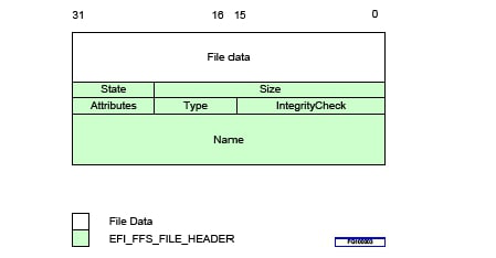
Fig. 2.5 Typical FFS File Layout
Figure 4 illustrates the layout of a PI Architecture Firmware File larger than 16 Mb:
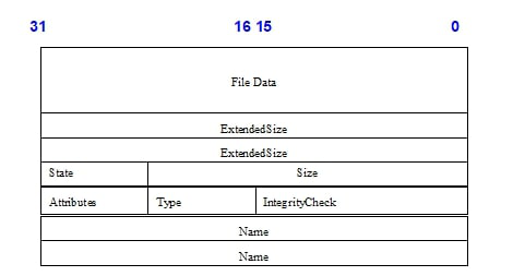
Fig. 2.6 File Header 2 layout for files larger than 16Mb
2.2.4. Firmware File Section Format
This section describes the standard firmware file section layout.
Each section begins with a section header, followed by data defined by the section type.
The section headers aligned on 4 byte boundaries relative to the start of the file’s image. If padding is required between the end of one section and the beginning of the next to achieve the 4-byte alignment requirement, all padding bytes must be initialized to zero.
Many section types are variable in length and are more accurately described as data streams rather than data structures.
Regardless of section type, all section headers begin with a 24-bit integer indicating the section size, followed by an 8-bit section type. The format of the remainder of the section header and the section data is defined by the section type. If the section size is 0xFFFFFF then the size is defined by a 32-bit integer that follows the 32-bit section header. Figures 5 and 6 shows the general format of a section.

Fig. 2.7 Format of a section (below 16Mb)

Fig. 2.8 Format of a section using the ExtendedLengthfield
2.2.5. File System Initialization
The algorithm below describes a method of FFS initialization that ensures FFS file corruption can be detected regardless of the cause.
The State byte of each file must be correctly managed to
ensure the integrity of the file system is not compromised in
the event of a power failure during any FFS operation. It is
expected that an FFS driver will produce an instance of the
Firmware Volume Protocol and that all normal file operations
will take place in that context. All file operations must
follow all the creation, update, and deletion rules described
in this specification to avoid file system corruption.
The following FvCheck() pseudo code must be executed during
FFS initialization to avoid file system corruption. If at any
point a failure condition is reached, then the firmware volume
is corrupted and a crisis recovery is initiated.All FFS files,
including files of type EFI_FV_FILETYPE_FFS_PAD must be
evaluated during file system initialization. It is legal for
multiple pad files with this file type to have the same Name
field in the file header. No checks for duplicate files should
be performed on pad files.
// Firmware volume initialization entry point - returns TRUE
// if FFS driver can use this firmware volume.
BOOLEAN FvCheck(Fv)
{
  // first check out firmware volume header
  if (FvHeaderCheck(Fv) == FALSE) {
    FAILURE();// corrupted firmware volume header
  }
  if (!((Fv->FvFileSystemId == EFI_FIRMWARE_FILE_SYSTEM2_GUID) || \
  (Fv->FvFileSystemId == EFI_FIRMWARE_FILE_SYSTEM3_GUID))){
    return (FALSE);   // This firmware volume is not
                      // formatted with FFS
  }
  // next walk files and verify the FFS is in good shape
  for (FilePtr = FirstFile; Exists(Fv, FilePtr);
          FilePtr = NextFile(Fv, FilePtr)) {
    if (FileCheck (Fv, FilePtr) != 0) {
      FAILURE(); // inconsistent file system
    }
  }
  if (CheckFreeSpace (Fv, FilePtr) != 0) {
    FAILURE();
  }
  return (TRUE);      // this firmware volume can be used by the FFS
                      // driver and the file system is OK
}
// FvHeaderCheck - returns TRUE if FvHeader checksum is OK.
BOOLEAN FvHeaderCheck (Fv)
{
  return (Checksum (Fv.FvHeader) == 0);
}
// Exists - returns TRUE if any bits are set in the file header
BOOLEAN Exists(Fv, FilePtr)
{
  return (BufferErased (Fv.ErasePolarity,
                FilePtr, sizeof (EFI_FIRMWARE_VOLUME_HEADER) == FALSE);
}
// BufferErased - returns TRUE if no bits are set in buffer
BOOLEAN BufferErased (ErasePolarity, BufferPtr, BufferSize)
{
  UINTN Count;
  if (Fv.ErasePolarity == 1) {
    ErasedByte = 0xff;
  } else {
    ErasedByte = 0;
  }
  for (Count = 0; Count < BufferSize; Count++) {
    if (BufferPtr[Count] != ErasedByte) {
      return FALSE;
    }
  }
  return TRUE;
}
// GetFileState - returns high bit set of state field.
  UINT8 GetFileState (Fv, FilePtr) {
  UINT8 FileState;
  UINT8 HighBit;
  FileState = FilePtr->State;
  if (Fv.ErasePolarity != 0) {
    FileState = ~FileState;
  }
  HighBit = 0x80;
  while (HighBit != 0 && (HighBit & FileState) == 0) {
    HighBit = HighBit >> 1;
  }
  return HighBit;
}
// FileCheck - returns TRUE if the file is OK
BOOLEAN FileCheck (Fv, FilePtr) {
  switch (GetFileState (Fv, FilePtr)) {
    case EFI_FILE_HEADER_CONSTRUCTION:
      SetHeaderBit (Fv, FilePtr, EFI_FILE_HEADER_INVALID);
      break;
    case EFI_FILE_HEADER_VALID:
      if (VerifyHeaderChecksum (FilePtr) != TRUE) {
        return (FALSE);
      }
      SetHeaderBit (Fv, FilePtr, EFI_FILE_DELETED);
      Break;
    case EFI_FILE_DATA_VALID:
      if (VerifyHeaderChecksum (FilePtr) != TRUE) {
        return (FALSE);
      }
      if (VerifyFileChecksum (FilePtr) != TRUE) {
        return (FALSE);
      }
      if (DuplicateFileExists (Fv, FilePtr,
                      EFI_FILE_DATA_VALID) != NULL) {
        return (FALSE);
      }
      break;
    case EFI_FILE_MARKED_FOR_UPDATE:
      if (VerifyHeaderChecksum (FilePtr) != TRUE) {
        return (FALSE);
      }
      if (VerifyFileChecksum (FilePtr) != TRUE) {
        return (FALSE);
      }
      if (FilePtr->State & EFI_FILE_DATA_VALID) == 0) {
        return (FALSE);
      }
      if (FilePtr->Type == EFI_FV_FILETYPE_FFS_PAD) {
        SetHeaderBit (Fv, FilePtr, EFI_FILE_DELETED);
      }
      else {
        if (DuplicateFileExists (Fv, FilePtr, EFI_FILE_DATA_VALID)) {
          SetHeaderBit (Fv, FilePtr, EFI_FILE_DELETED);
        }
        else {
          if (Fv->Attributes & EFI_FVB_STICKY_WRITE) {
            CopyFile (Fv, FilePtr);
            SetHeaderBit (Fv, FilePtr, EFI_FILE_DELETED);
          }
          else {
            ClearHeaderBit (Fv, FilePtr, EFI_FILE_MARKED_FOR_UPDATE);
          }
        }
      }
      break;
    case EFI_FILE_DELETED:
      if (VerifyHeaderChecksum (FilePtr) != TRUE) {
        return (FALSE);
      }
      if (VerifyFileChecksum (FilePtr) != TRUE) {
        return (FALSE);
      }
      break;
    case EFI_FILE_HEADER_INVALID:
      break;
  }
  return (TRUE);
}
// FFS_FILE_PTR * DuplicateFileExists (Fv, FilePtr, StateBit)
//    This function searches the firmware volume for another occurrence
//    of the file described by FilePtr, in which the duplicate files
// high state bit that is set is defined by the parameter StateBit.
// It returns a pointer to a duplicate file if it exists and NULL
// if it does not. If the file type is EFI_FV_FILETYPE_FFS_PAD
// then NULL must be returned.

// CopyFile (Fv, FilePtr)
//    The purpose of this function is to clear the
//    EFI_FILE_MARKED_FOR_UPDATE bit from FilePtr->State
//    in firmware volumes that have EFI_FVB_STICKY_WRITE == TRUE.
//    The file is copied exactly header and all, except that the
//    EFI_FILE_MARKED_FOR_UPDATE bit in the file header of the
//    new file is clear.
// VerifyHeaderChecksum (FilePtr)
//    The purpose of this function is to verify the file header
//    sums to zero. See IntegrityCheck.Checksum.Header definition
//    for details.
// VerifyFileChecksum (FilePtr)
//    The purpose of this function is to verify the file integrity
//    check. See IntegrityCheck.Checksum.File definition for details.
2.2.6. Traversal and Access to Files
The Security (SEC), PEI, and early DXE code must be able to traverse the FFS and read and execute files before a write-enabled DXE FFS driver is initialized. Because the FFS may have inconsistencies due to a previous power failure or other system failure, it is necessary to follow a set of rules to verify the validity of files prior to using them. It is not incumbent on SEC, PEI, or the early read-only DXE FFS services to make any attempt to recover or modify the file system. If any situation exists where execution cannot continue due to file system inconsistencies, a recovery boot is initiated.
There is one inconsistency that the SEC, PEI, and early DXE
code can deal with without initiating a recovery boot. This
condition is created by a power failure or other system failure
that occurs during a file update on a previous boot. Such a
failure will cause two files with the same file name GUID to
exist within the firmware volume. One of them will have the
EFI_FILE_MARKED_FOR_UPDATE bit set in its State field but
will be otherwise a completely valid file. The other one may be
in any state of construction up to and including
EFI_FILE_DATA_VALID . All files used prior to the
initialization of the write-enabled DXE FFS driver must be
screened with this test prior to their use. If this condition
is discovered, it is permissible to initiate a recovery boot
and allow the recovery DXE to complete the update.
The following pseudo code describes the method for determining which of these two files to use. The inconsistency is corrected during the write-enabled initialization of the DXE FFS driver.
// Screen files to ensure we get the right one in case
// of an inconsistency.
FFS_FILE_PTR EarlyFfsUpdateCheck(FFS_FILE_PTR * FilePtr) {
  FFS_FILE_PTR * FilePtr2;
  if (VerifyHeaderChecksum (FilePtr) != TRUE) {
    return (FALSE);
  }
  if (VerifyFileChecksum (FilePtr) != TRUE) {
    return (FALSE);
  }
  switch (GetFileState (Fv, FilePtr)) {
    case EFI_FILE_DATA_VALID:
      return (FilePtr);
      break;
    case EFI_FILE_MARKED_FOR_UPDATE:
      FilePtr2 = DuplicateFileExists (Fv, FilePtr,
                            EFI_FILE_DATA_VALID);
      if (FilePtr2 != NULL) {
        if (VerifyHeaderChecksum (FilePtr) != TRUE) {
          return (FALSE);
        }
        if (VerifyFileChecksum (FilePtr) != TRUE) {
          return (FALSE);
        }
        return (FilePtr2);
      } else {
        return (FilePtr);
      }
      break;
  }
}
Note: There is no check for duplicate files once a file in the
EFI_FILE_DATA_VALID state is located. The condition where
two files in a single firmware volume have the same file
name GUID and are both in the EFI_FILE_DATA_VALID state
cannot occur if the creation and update rules that are
defined in this specification are followed.
2.2.7. File Integrity and State
File corruption, regardless of the cause, must be detectable so that appropriate file system repair steps may be taken. File corruption can come from several sources but generally falls into three categories:
General failure
Erase failure
Write failure
A general failure is defined to be apparently random corruption of the storage media. This corruption can be caused by storage media design problems or storage media degradation, for example. This type of failure can be as subtle as changing a single bit within the contents of a file. With good system design and reliable storage media, general failures should not happen. Even so, the FFS enables detection of this type of failure.
An erase failure occurs when a block erase of firmware volume media is not completed due to a power failure or other system failure. While the erase operation is not defined, it is expected that most implementations of FFS that allow file write and delete operations will also implement a mechanism to reclaim deleted files and coalesce free space. If this operation is not completed correctly, the file system can be left in an inconsistent state.
Similarly, a write failure occurs when a file system write is in progress and is not completed due to a power failure or other system failure. This type of failure can leave the file system in an inconsistent state.
All of these failures are detectable during FFS initialization,
and, depending on the nature of the failure, many recovery
strategies are possible. Careful sequencing of the State bits
during normal file transitions is sufficient to enable
subsequent detection of write failures. However, the State
bits alone are not sufficient to detect all occurrences of
general and/or erase failures. These types of failures require
additional support, which is enabled with the file header
IntegrityCheck field.
For sample code that provides a method of FFS initialization that can detect FFS file corruption, regardless of the cause, see File System Initialization.
2.2.8. File State Transitions
2.2.8.1. Overview
There are three basic operations that may be done with the FFS:
Creating a file
Deleting a file
Updating a file
All state transitions must be done carefully at all times to
ensure that a power failure never results in a corrupted
firmware volume. This transition is managed using the
State field in the file header.
For the purposes of the examples below, positive decode
logic is assumed ( EFI_FVB_ERASE_POLARITY = 0 ). In actual
use, the EFI_FVB_ERASE_POLARITY in the firmware volume
header is referenced to determine the truth value of all FFS
State bits. All State bit transitions must be atomic
operations. Further, except when specifically noted, only
the most significant State bit that is TRUE has meaning.
Lower-order State bits are superseded by higher-order
State bits.
Type EFI_FVB_ERASE_POLARITY is defined in `
EFI_FIRMWARE_VOLUME_HEADER. <V3-Code-Definitions.htm#92285>`__.
2.2.8.2. Initial State
The initial condition is that of “free space.” All free
space in a firmware volume must be initialized such that all
bits in the free space contain the value of
EFI_FVB_ERASE_POLARITY . As such, if the free space is
interpreted as an FFS file header, all State bits are
FALSE .
Type EFI_FVB_ERASE_POLARITY is defined in `
EFI_FIRMWARE_VOLUME_HEADER. <V3-Code-Definitions.htm#92285>`__
2.2.8.3. Creating a File
A new file is created by allocating space from the firmware volume immediately beyond the end of the preceding file (or the firmware volume header if the file is the first one in the firmware volume). Creating a File illustrates the steps to create a new file, which are detailed below the figure.
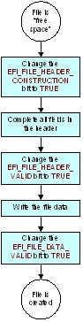
Fig. 2.9 Creating a File
As shown in Creating a File, the following steps are required to create a new file:
Allocate space in the firmware volume for a new file header, either
EFI_FFS_FILE_HEADER, orEFI_FFS_FILE_HEADER2if the file is 16MB or more in size, and complete all fields of the header (except for theStatefield, which is updated independently from the rest of the header). This allocation is done by interpreting the free space as a file header and changing theEFI_FILE_HEADER_CONSTRUCTIONbit toTRUE. The transition of this bit to theTRUEstate must be atomic and fully complete before any additional writes to the firmware volume are made. This transition yieldsState= 00000001b, which indicates the header construction has begun but has not yet been completed. This value has the effect of “claiming” the FFS header space from the firmware volume free space.While in this state, the following fields of the FFS header are initialized and written to the firmware volume:
NameIntegrityCheck.HeaderTypeAttributesSize
If
FFS_ATTRIB_LARGE_FILEis set inAttributestheSizefield of the FFS header must be zero andExtendedSizemust contian the size of the FFS file.The value ofIntegrityCheck.Headeris calculated as described inEFI_FFS_FILE_HEADER.Mark the new header as complete and write the file data. To mark the header as complete, the
EFI_FILE_HEADER_VALIDbit is changed toTRUE. The transition of this bit to theTRUEstate must be atomic and fully complete before any additional writes to the firmware volume are made. This transition yieldsState= 00000011b, which indicates the header construction is complete, but the file data has not yet been written. This value has the effect of “claiming” the full length of the file from the firmware volume free space. Once theEFI_FILE_HEADER_VALIDbit is set, no further changes to the following fields may be made:
Name
IntegrityCheck.Header
Type
Attributes
SizeWhile in this state, the file data and
IntegrityCheck.Fileare written to the firmware volume. The order in which these are written does not matter. The calculation of the value forIntegrityCheck.Fileis described in `EFI_FFS_FILE_HEADERFirmware Storage Code Definitions .
Mark the data as valid. To mark the data as valid, the
EFI_FILE_DATA_VALIDbit is changed toTRUE. The transition of this bit to theTRUEstate must be atomic and fully complete before any additional writes to the firmware volume are made. This transition yieldsState= 00000111b, which indicates the file data is fully written and is valid.
2.2.8.4. Deleting a File
Any file with EFI_FILE_HEADER_VALID set to TRUE and
EFI_FILE_HEADER_INVALID and EFI_FILE_DELETED set to FALSE
is a candidate for deletion.
To delete a file, the EFI_FILE_DELETED bit is set to the
TRUE state. The transition of this bit to the TRUE state
must be atomic and fully complete before any additional writes
to the firmware volume are made. This transition yields State
= 0001xx11b , which indicates the file is marked deleted. Its
header is still valid, however, in as much as its length field
is used in locating the next file in the firmware volume.
Note: The EFI_FILE_HEADER_INVALID bit must be left in the
FALSE state.
2.2.8.5. Updating a File
A file update is a special case of file creation where the file
being added already exists in the firmware volume. At all times
during a file update, only one of the files, either the new one
or the old one, is valid at any given time. This validation is
possible by using the EFI_FILE_MARKED_FOR_UPDATE bit in the
old file.
Updating a File illustrates the steps to update a file, which are detailed below the figure.
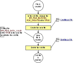
Fig. 2.10 Updating a File
As shown in Updating a File, the following steps are required to update a file:
Set the
EFI_FILE_MARKED_FOR_UPDATEbit toTRUEin the old file. The transition of this bit to theTRUEstate must be atomic and fully complete before any additional writes to the firmware volume are made. This transition yieldsState= 00001111b, which indicates the file is marked for update. A file in this state remains valid as long as no other file in the firmware volume has the same name and aStateof000001xxb.Create the new file following the steps described in Creating a File. When the new file becomes valid, the old file that was marked for update becomes invalid. That is to say, a file marked for update is valid only as long as there is no file with the same name in the firmware volume that has a
Stateof000001xxb. In this way, only one of the files, either the new or the old, is valid at any given time. The act of writing theEFI_FILE_DATA_VALIDbit in the new file’sStatefield has the additional effect of invalidating the old file.Delete the old file following the steps described in Deleting a File..