2. Overview
The Pre-EFI Initialization (PEI) phase of the PI Architecture specifications (hereafter referred to as the “PI Architecture”) is invoked quite early in the boot flow. Specifically, after some preliminary processing in the Security (SEC) phase, any machine restart event will invoke the PEI phase.
The PEI phase will initially operate with the platform in a nascent state, leveraging only on-processor resources, such as the processor cache as a call stack, to dispatch Pre-EFI Initialization Modules (PEIMs). These PEIMs are responsible for the following:
Initializing some permanent memory complement
Describing the memory in Hand-Off Blocks (HOBs)
Describing the firmware volume locations in HOBs
Passing control into the Driver Execution Environment (DXE) phase
Philosophically, the PEI phase is intended to be the thinnest amount of code to achieve the ends listed above. As such, any more sophisticated algorithms or processing should be deferred to the DXE phase of execution.
The PEI phase is also responsible for crisis recovery and resuming from the S3 sleep state. For crisis recovery, the PEI phase should reside in some small, fault-tolerant block of the firmware store. As a result, it is imperative to keep the footprint of the PEI phase as small as possible. In addition, for a successful S3 resume, the speed of the resume is of utmost importance, so the code path through the firmware should be minimized. These two boot flows also speak to the need to keep the processing and code paths in the PEI phase to a minimum.
The implementation of the PEI phase is more dependent on the processor architecture than any other phase. In particular, the more resources the processor provides at its initial or near initial state, the richer the interface between the PEI Foundation and PEIMs. As such, there are several parts of the following discussion that note requirements on the architecture but are otherwise left architecturally dependent.
2.1. Design Goals
The PI Architecture requires the PEI phase to configure a system to meet the minimum prerequisites for the Driver Execution Environment (DXE) phase of the PI Architecture architecture. In general, the PEI phase is required to initialize a linear array of RAM large enough for the successful execution of the DXE phase elements.
The PEI phase provides a framework to allow vendors to supply separate initialization modules for each functionally distinct piece of system hardware that must be initialized prior to the DXE phase of execution in the PI Architecture. The PEI phase provides a common framework through which the separate initialization modules can be independently designed, developed, and updated. The PEI phase was developed to meet the following goals in the PI architecture:
Enable maintenance of the “chain of trust.” This includes protection against unauthorized updates to the PEI phase or its modules, as well as a form of authentication of the PEI
Foundation and its modules during the PEI phase.
Provide a core PEI module (the PEI Foundation) that will remain more or less constant for a particular processor architecture but that will support add-in modules from various vendors, particular for processors, chipsets, RAM initialization, and so on.
Allow independent development of early initialization modules.
2.2. Pre-EFI Initialization (PEI) Phase
The design for the Pre-EFI Initialization (PEI) phase of a PI Architecture-compliant boot is as an essentially miniature version of the DXE phase of the PI Architecture and addresses many of the same issues. The PEI phase is designed to be developed in several parts. The PEI phase consists of the following:
Some core code known as the PEI Foundation
Specialized plug-ins known as Pre-EFI Initialization Modules (PEIMs)
Unlike DXE, the PEI phase cannot assume the availability of reasonable amounts of RAM, so the richness of the features in DXE does not exist in PEI. The PEI phase limits its support to the following actions:
Locating, validating, and dispatching PEIMs
Facilitating communication between PEIMs
Providing handoff data to subsequent phases
See PEI Operations Diagram. below shows a diagram of the process completed during the PEI phase.
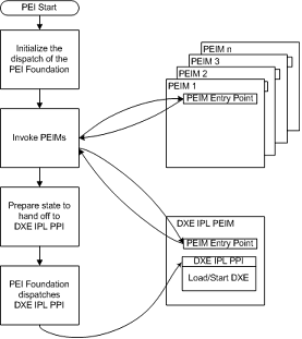
Fig. 2.1 PEI Operations Diagram
2.3. PEI Services
The PEI Foundation establishes a system table named the PEI Services Table that is visible to all Pre-EFI Initialization Modules (PEIMs) in the system. A PEI Service is defined as a function, command, or other capability manifested by the PEI Foundation when that service’s initialization requirements are met. Because the PEI phase has no permanent memory available until nearly the end of the phase, the range of services created during the PEI phase cannot be as rich as those created during later phases. Because the location of the PEI Foundation and its temporary RAM is not known at build time, a pointer to the PEI Services Table is passed into each PEIM’s entry point and also to part of each PEIM-to-PEIM Interface (PPI).
The PEI Foundation provides the classes of services listed in See PEI Foundation Classes of Service. .
PPI Services |
Manages PPIs to facilitate intermodule calls between PEIMs Interfaces are installed and tracked on a database maintained in temporary RAM |
|---|---|
Boot Mode Services |
Manages the boot mode S3 S5 normal boot diagnostics etc of the system |
HOB Services |
Creates data structures called Hand Off Blocks HOBs that are used to pass information to the next phase of the PI Architecture |
Firmware Volume Services |
Finds PEIMs and other firmware files in the firmware volumes |
PEI Memory Services |
Provides a collection of memory management services for use both before and after permanent memory has been discovered |
Status Code Services |
Provides common progress and error code reporting services for example port 080h or a serial port for simple text output for debug |
Reset Services |
Provides a common means by which to initiate a warm or cold restart of the system |
2.4. PEI Foundation
The PEI Foundation is the entity that is responsible for the following:
Successfully dispatching Pre-EFI Initialization Modules (PEIMs)
Maintaining the boot mode
Initializing permanent memory
Invoking the Driver Execution Environment (DXE) loader
The PEI Foundation is written to be portable across all platforms of a given instruction-set architecture. As such, a binary for 32-bit Intel ® architecture (IA-32) should work across all Pentium ® processors, from the Pentium II processor with MMX™ technology through the latest Pentium 4 processors. Similarly, the PEI Foundation binary for the Itanium ® processor family should work across all Itanium processors.
Regardless of the processor microarchitecture, the set of services exposed by the PEI Foundation should be the same. This uniform surface area around the PEI Foundation allows PEIMs to be written in the C programming language and compiled across any microarchitecture.
2.5. PEI Dispatcher
The PEI Dispatcher is essentially a state machine that is implemented in the PEI Foundation. The PEI Dispatcher evaluates the dependency expressions in Pre-EFI Initialization Modules (PEIMs) that are in the firmware volume(s) being examined.
The dependency expressions are logical combinations of
PEIM-to-PEIM Interfaces (PPIs). These expressions describe the
PPIs that must be available before a given PEIM can be invoked.
To evaluate the dependency expression for the PEIM, the PEI
Dispatcher references the PPI database in the PEI Foundation to
determine which PPIs have been installed. If the PPI has been
installed, the dependency expression will evaluate to TRUE,
which tells the PEI Dispatcher it can run the PEIM. At this
point, the PEI Foundation passes control to the PEIM with a
true dependency expression.
Once the PEI Dispatcher has evaluated all of the PEIMs in all
of the exposed firmware volumes and no more PEIMs can be
dispatched (i.e., the dependency expressions do not evaluate
from FALSE to TRUE ), the PEI Dispatcher will exit. It is
at this point that the PEI Dispatcher cannot invoke any
additional PEIMs. The PEI Foundation then reassumes control
from the PEI Dispatcher and invokes the DXE IPL PPI to pass
control to the DXE phase of execution.
2.6. Pre-EFI Initialization Modules (PEIMs)
Pre-EFI Initialization Modules (PEIMs) are specialized drivers that personalize the PEI Foundation to the platform. They are analogous to DXE drivers and generally correspond to the components being initialized. It is the responsibility of the PEI Foundation code to dispatch the PEIMs in a sequenced order and provide basic services. The PEIMs are intended to mirror the components being initialized.
Communication between PEIMs is not easy in a “memory poor” environment. Nonetheless, PEIMs cannot be coded without some interaction between one another and, even if they could, it would be inefficient to do so. The PEI phase provides mechanisms for PEIMs to locate and invoke interfaces from other PEIMs.
Because the PEI phase exists in an environment where minimal hardware resources are available and execution is performed from the boot firmware device, it is strongly recommended that PEIMs do the minimum necessary work to initialize the system to a state that meets the prerequisites of the DXE phase.
It is expected that, in the future, common practice will be that the vendor of a software or hardware component will provide the PEIM (possibly in source form) so the customer can debug integration problems quickly.
2.7. PEIM-to-PEIM Interfaces (PPIs)
PEIMs communicate with each other using a structure called a
PEIM-to-PEIM Interface (PPI). PPIs are contained in a
EFI_PEI_PPI_DESCRIPTOR data structure, which is composed of a
GUID/pointer pair. The GUID “names” the interface and the
associated pointer provides the associated data structure
and/or service set for that PPI. A consumer of a PPI must use
the PEI Service LocatePpi() to discover the PPI of interest.
The producer of a PPI publishes the available PPIs in its PEIM
using the PEI Services InstallPpi() or ReinstallPpi().
All PEIMs are registered and located in the same fashion, namely through the PEI Services listed above. Within this name space of PPIs, there are two classes of PPIs:
Architectural PPIs
Additional PPIs
An architectural PPI is a PPI whose GUID is described in the
PEI CIS and is a GUID known to the PEI Foundation. These
architectural PPIs typically provide a common interface to the
PEI Foundation of a service that has a platform-specific
implementation, such as the PEI Service ReportStatusCode().
Additional PPIs are PPIs that are important for interoperability but are not depended upon by the PEI Foundation. They can be classified as mandatory or optional. Specifically, to have a large class of interoperable PEIMs, it would be good to signal that the final boot mode was installed in some standard fashion so that PEIMs could use this PPI in their dependency expressions. The alternative to defining these additional PPIs in the PEI CIS would be to have a proliferation of similar services under different names.
2.8. Firmware Volumes
Pre-EFI Initialization Modules (PEIMs) reside in firmware volumes (FVs). The PEI phase supports the ability for PEIMs to reside in multiple firmware volumes.. Other PEIMs can expose firmware volumes for use by the PEI Foundation.