12. Special Paths Unique to the Itanium® Processor Family
12.1. Introduction
The Itanium processor family supports the full complement of boot modes listed in the PEI CIS. In addition, however, Itanium® architecture requires an augmented flow. This flow includes a “recovery check call” in which all processors execute the PEI Foundation when an Itanium platform restarts. Each processor has its own version of temporary memory such that there are as many concurrent instances of PEI execution as there are Itanium processors.
There is a point in the multiprocessor flow, however, when all processors have to call back into the Processor Abstraction Layer A (PAL-A) component to assess whether the processor revisions and PAL-B binaries are compatible. This callback into the PAL-A does not preserve the state of the temporary memory, however. When the PAL-A returns control back to the various processors, the PEI Foundation and its associated data structures have to be reinstantiated.
At this point, however, the flow of the PEI phase is the same as for IA-32 Intel architecture in that all processors make forward progress up through invoking the DXE IPL PPI.
12.2. Unique Boot Paths for Itanium Architecture
Intel® Itanium processors possess two unique boot paths that also invoke the dispatcher located at the System Abstraction Layer entry point (SALE_ENTRY):
Processor INIT
Machine Check (MCHK)
INIT and MCHK are two asynchronous events that start up the Security (SEC) code/dispatcher in an Itanium®-based system. The PI Architecture security module is transparent during all the code paths except for the recovery check call that happens during a cold boot. The PEIMs that handle these events are architecture aware and do not return control to the PEI Dispatcher. They call their respective architectural handlers in the operating system.
Itanium Processor Boot Path (INIT and MCHK) shows the boot path for INIT and MCHK events.
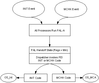
Fig. 12.1 Itanium Processor Boot Path (INIT and MCHK)
12.3. Min-State Save Area
When the Processor Abstraction Layer (PAL) hands control to the dispatcher, it will supply the following:
Unique handoff state in the registers
A pointer, called the min-state pointer, to the minimum-state saved buffer area
This buffer is a unique per-processor save area that is
registered to each processor during the normal OS boot path.
The PI Architecture defines a unique, PI Architecture-specific
data pointer, EFI_PEI_MIN_STATE_DATA, that is attached to
this min-state pointer. This data structure is defined in the
next topic.
Min-State Buffer Organization
shows a typical organization of a min-state buffer. The PEI
Data Pointer references EFI_PEI_MIN_STATE_DATA.
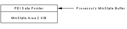
Fig. 12.2 Min-State Buffer Organization
12.3.1. EFI_PEI_MIN_STATE_DATA
Note: This data structure is for the Itanium processor family only.
Summary
A structure that encapsulates the Processor Abstraction Layer (PAL) min-state data structure for purposes of firmware state storage and reference.
Prototype
typedef struct {
  UINT64  OsInitHandlerPointer;
  UINT64  OsInitHandlerGP;
  UINT64  OsInitHandlerChecksum;
  UINT64  OSMchkHandlerPointer;
  UINT64  OSMchkHandlerGP;
  UINT64  OSMchkHandlerChecksum;
  UINT64  PeimInitHandlerPointer;
  UINT64  PeimInitHandlerGP;
  UINT64  PeimInitHandlerChecksum;
  UINT64  PeimMchkHandlerPointer;
  UINT64  PeimMchkHandlerGP;
  UINT64  PeimMckhHandlerChecksum;
  UINT64  TypeOfOSBooted;
  UINT8   MinStateReserved[0x400];
  UINT8   OEMReserved[0x400];
} EFI_PEI_MIN_STATE_DATA;
Parameters
OsInitHandlerPointerThe address of the operating system’s INIT handler. The INIT is a restart type for the Itanium processor family.
OsInitHandlerGPThe value of the operating system’s INIT handler’s General Purpose (GP) register. Per the calling conventions for the Itanium processor family, the GP must be set before invoking the function.
OsInitHandlerChecksumA 64-bit checksum across the contents of the operating system’s INIT handler. This can be used by the PEI firmware to corroborate the integrity of the INIT handler prior to invocation.
OSMchkHandlerPointerThe address of the operating system’s Machine Check (MCHK) handler. MCHK is a restart type for the Itanium processor family.
OSMchkHandlerGPThe value of the operating system’s MCHK handler’s GP register. Per the calling conventions for the Itanium processor family, the GP must be set before invoking the function.
OSMchkHandlerChecksumA 64-bit checksum across the contents of the operating system’s MCHK handler. This can be used by the PEI firmware to corroborate the integrity of the MCHK handler prior to invocation.
PeimInitHandlerPointerThe address of the PEIM’s INIT handler.
PeimInitHandlerGPThe value of the PEIM’s INIT handler’s GP register. Per the calling conventions for the Itanium processor family, the GP must be set before invoking the function.
PeimInitHandlerChecksumA 64-bit checksum across the contents of the PEIM’s INIT handler. This can be used by the PEI firmware to corroborate the integrity of the INIT handler prior to invocation.
PeimMchkHandlerPointerThe address of the PEIM’s MCHK handler.
PeimMchkHandlerGPThe value of the PEIM’s MCHK handler’s GP register. Per the calling conventions for the Itanium processor family, the GP must be set before invoking the function.
PeimMckhHandlerChecksumA 64-bit checksum across the contents of the PEIM’s MCHK handler. This can be used by the PEI firmware to corroborate the integrity of the MCHK handler prior to invocation.
TypeOfOSBootedDetails the type of operating system that was originally booted. This allows for different preliminary processing in firmware based upon the target OS.
MinStateReservedReserved bytes that must not be interpreted by OEM firmware. Future versions of PEI may choose to expand in this range.
OEMReservedReserved bytes for the OEM. PEI core components should not attempt to interpret the contents of this region.
Description
A 64-bit PEI data pointer is defined at the beginning of the
Itanium processor family min-state data structure. This data
pointer references an EFI_PEI_MIN_STATE_DATA structure that
is defined above. This latter structure contains the entry
points of INIT and MCHK code blocks. The pointers are defined
such that the INIT and MCHK code can be either written as
ROM-based PEIMs or as DXE drivers. The distinction between PEIM
and DXE driver are at the OEM’s discretion.
In Itanium® architecture, the PEI firmware must register a min-state with the PAL. This min-state is memory when the PAL code can deposit processor-specific information upon various restart events (INIT, RESET, Machine Check). Upon receipt of INIT or MCHK, the PEI firmware shall first invoke the PEIM INIT or MCHK handlers, respectively, and then the OS INIT or MCHK handler. The min-state data structure is a natural location from which to reference the PEI data structure that contains these latter entry points.
12.4. Dispatching Itanium Processor Family PEIMs
The Itanium processor family dispatcher starts dispatching all the PEIMs as it resolves the dependency grammar contained within their headers. Because all Itanium processors enter into SALE_ENTRY for a recovery check, some of the PEIMs will contain multiprocessor (MP) code and will work on all processors. The behavior of a particular PEIM that is dispatched depends on the following:
Handoff state given by the Processor Abstraction Layer (PAL)
The boot mode flag
Once the processor runs some code and one of the recovery check PEIM determines that the firmware needs to be recovered, it flips the boot flag to recovery and invokes the dispatcher again in recovery mode.
If it is a nonrecovery situation (normal boot), then the recovery check PEIM wakes up all the processors and returns them to PAL-A for further initialization. Note that when control for a normal boot returns back to the PAL to run PAL-B code, all of the register contents are lost. When control returns to the dispatcher, the PEIMs gain control in the dispatched order and can determine the memory topology (if needed in a platform implementation) by reading the memory controller registers of the chipset. The PEIMs can then build Hand-Off Blocks (HOBs).
When the first phase is done, there will be coherent memory on the system that all the node processors can see. The system then begins to execute the dispatcher in a second phase, during which it builds HOBs. On a multinode system with many processors, the configuration of memory may take several steps and therefore quite a bit of code.
When the second phase is done, the last PEIM will build DXE as described in PEI to DXE Handoff and hand control to the PI Architecture DXE phase for further initialization of the platform.
Boot Path in Itanium Processors depicts the initial flow between PAL-A , PAL-B, and the PEI Foundation located at SALE_ENTRY point.
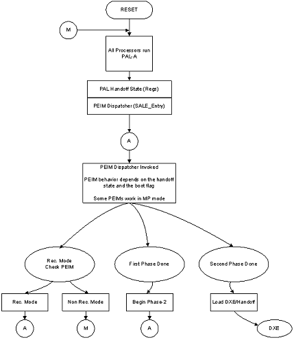
Fig. 12.3 Boot Path in Itanium Processors