Display-specific Methods
The methods described in this section are all associated with specific display devices. This device-specific association is represented in the namespace example in the previous section by the positioning of these methods in a device tree.
_DOS (Enable/Disable Output Switching)
Many ACPI machines currently reprogram the active display output automatically when the user presses the display toggle switch on the keyboard. This is done because most video device drivers are currently not capable of being notified synchronously of such state changes. However, this behavior violates the ACPI specification, because the system modifies some graphics device registers.
The existence of the _DOS method indicates that the platform runtime firmware is capable of automatically switching the active display output or controlling the brightness of the LCD. If it exists at all, the _DOS method must be present for all display output devices. This method is required if the system supports display switching or LCD brightness control.
Arguments:(1)
Arg0 - An Integer containing the encoded switching controls (see below)
Return Value:
None
Additional Argument Information:
Bits [1:0]:
0 - The platform runtime firmware should not automatically switch
(toggle) the active display output, but instead just save the desired
state change for the display output devices in variables associated with
each display output, and generate the display switch event. OSPM can
query these state changes by calling the \_DGS method.

1 - The platform runtime firmware should automatically switch (toggle)
the active display output, with no interaction required on the OS part.
The display switch event should not be generated in this case.

2 - The \_DGS values should be locked. It's highly recommended that the
platform runtime firmware do nothing when hotkey pressed. No switch, no
notification.

3 - The platform runtime firmware should not automatically switch
(toggle) the active display output, but instead generate the display
switch event notify codes 0x82, 0x83, or 0x84. OSPM will determine what
display output state should be set, and change the display output state
without further involvement from the platform runtime firmware.
Bit [2]:
0 - The platform runtime firmware should automatically control the
brightness level of the LCD when the power changes from AC to DC.

1 - The platform runtime firmware should not automatically control the
brightness level of the LCD when the power changes from AC to DC.
The _DOS method controls this automatic switching behavior. This method should do so by saving the parameter passed to this method in a global variable somewhere in the platform runtime firmware data segment. The platform runtime firmware then checks the value of this variable when doing display switching. This method is also used to control the generation of the display switching Notify (VGA, 0x80/0x81).
The platform runtime firmware, when doing switching of the active display, must verify the state of the variable set by the _DOS method. The default value of this variable must be 1.
_DOD (Enumerate All Devices Attached to the Display Adapter)
This method is used to enumerate devices attached to the display adapter. This method is required if integrated controller supports output switching.
On many laptops today, a number of devices can be connected to the graphics adapter in the machine. These devices are on the motherboard and generally are not directly enumerable by the video driver; for this reason, all motherboard VGA attached devices are listed in the ACPI namespace.
These devices fall into two categories:
Video output devices. For example, a machine with a single display device on the motherboard can have three possible output devices attached to it, such as a TV, a CRT, or a panel.
Non-video output devices. For example, TV Tuner, DVD decoder, Video Capture. They just attach to VGA and their power management closely relates to VGA.
Both ACPI and the video driver have the ability to program and configure output devices. This means that both ACPI and the video driver must enumerate the devices using the same IDs. To solve this problem, the _DOD method returns a list of devices attached to the graphics adapter, along with device-specific configuration information. This information will allow the cooperation between ACPI components and the video driver.
Every child device enumerated in the ACPI namespace under the graphics adapter must be specified in this list of devices. Each display device must have its own ID, which is unique with respect to any other attachable devices enumerated.
Arguments:
None
Return Value:
A Package containing a variable-length list of Integers, each of which contains the 32-bit device attribute of a child device (See Table B-2 below).
Example
Method (_DOD, 0) {
   Return (
      Package()
      {
         0x00000110, // Primary LCD panel, not detectable by firmware
         0x80000100, // CRT type display, not detectable by firmware
         0x80000220, // TV type display, not detectable by the firmware
         0x80000411, // Secondary LCD panel, not detectable by firmware
      }
   )
}
Table B-2: Video Output Device Attributes
Bits |
Definition |
|---|---|
15:0 |
Device ID. The device ID must match the ID’s specified by Video Chip Vendors. They must also be unique under VGA namespace:
Bits [3:0] Display Index: A zero-based instance of the Display, when multiple displays of the same type are attached, regardless of where it is associated. Starting from the first adapter and its first display of the type on the first integrated internal device and then incrementing per device-function according to its relative port number.
Bits [7:4] Display Port Attachment: This field differentiates displays of the same type attached at different points of one adapter. The zero-based number scheme is specific to each Video Chip Vendors’ implementation.
Bits [11:8] Display Type: Decribes the specific type of Display Technology in use (see notes below table)::
0 – Other
1 – VGA* CRT or VESA* Compatible Analog Monitor
2 – TV/HDTV or other Analog-Video Monitor
3 – External Digital Monitor
4 – Internal/Integrated Digital Flat Panel
5-15 – Reserved for future use
Bits [15:12] Chipset-vendor specific
|
16 |
Platform boot firmware can detect the device. |
17 |
Non-VGA output device whose power is related to the VGA device. This can be used when specifying devices like TV Tuner, DVD decoder, Video Capture … etc. |
20:18 |
For VGA multiple-head devices, this specifies head or pipe ID e.g. for Dual-Pipe*, Dual-Display*, Duo-View*, TwinView*, Triple-View* … etc, beginning with 0 for head 0 or single-head device and increasing for each additional head. |
30:21 |
Reserved (must be 0) |
31 |
Device ID Scheme:
1 - Uses the bit-field definitions above (bits 15:0)
0 - Other scheme, contact the Video Chip Vendor
|
As mentioned in the above table, a “Pipe” or “Head” refers to a unique display content stream e.g. at a particular color-depth, resolution, and refresh-rate. The “Port” refers to the display output device attachment and may include a DAC, encoder or other mechanism required to support a given display end-point. The “Display Type” describes the generalized class of display output technology, and the means of integration. The “Display Index” is then an index that assists in creating a unique identifier display end-points in scenarios where other attributes are the same.
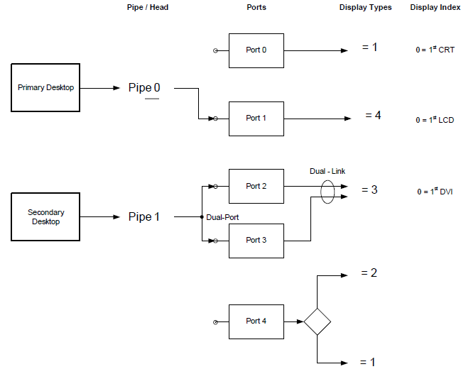
Fig. 6 Fig. B-1: Example Display Architecture
Table B-3: Example Device IDs
Bits |
Definition |
|---|---|
0x000xyyyy |
Bit [31] = 0. Other proprietary scheme - 0x110 Device ID is an exception. (See Note 3) |
0x00000110 |
Integrated LCD Panel #1 using a common, backwards compatible ID |
0x80000100 |
Integrated VGA CRT or VESA compatible Monitor #1 on Port0 |
0x80000240 |
Integrated TV #1 on Port4 |
0x80000410 |
Integrated Internal LCD Panel #1 on Port1 |
0x80000421 |
LVDS Panel #2 Dual-Link using Port2 & 3. (See Note 4) |
0x80000131 |
VGA CRT or VESA compatible Monitor #2 on Port3 |
0x80000121 |
Dual-Link VGA CRT or VESA compatible Monitor #2 using Port2 & 3. (See Note 4.) |
0x80000320 |
DVI Monitor #1 on Port2 (shares Port2 with a Dual-Function DVI/TV Encoder). (See Note 5) |
0x80000331 |
DVI Monitor #2 on Port3 |
0x80000330 |
Dual-Link DVI Monitor #1 using Port2 & 3 |
0x80000231 |
TV #2 on Port2 (shares Port2 with a Dual-Function DVI/TV Encoder). (See Note 5) |
Note
An “External Digital Monitor” is an external display device attachable via a user-accessible connector standard (e.g. DFP* or DVI* Compatible Monitors).
An “Internal Flat Panel” is a non-detachable fixed pixel display device, including a backlight, and is internally associated, without user-accessible connectors, to the Video Chip (e.g. TFT LCD via TMDS*, LVDS* interface).
When Bit [31] is 0, no assumptions can be made on which ID will be used for any particular display type. Contact the Video Chip vendor for details of the ID scheme employed.
In certain cases multiple Displays Ports may be combined to increase bandwidth for a particular Display in higher-resolution modes. In this situation, the Display Type and Port Number should remain the same in order to retain a consistent ID for the same device, regardless of the selected display mode.
In certain cases, more than one type of display (and connector) may be supportable on a single Port (e.g. DVI + TV + CRT on a single Display Encoder device), while only one display is selectable at any time. In this case, the Port Number field of the ID may be the same as other Display IDs, however the other fields (e.g. Display Type) provide uniqueness.
_ROM (Get ROM Data)
This method is used to get a copy of the display devices’ ROM data. This method is required when the ROM image is stored in a proprietary format such as stored in the platform firmware ROM. This method is not necessary if the ROM image can be read through a standard PCI interface (using ROM BAR). If _ROM is present, it is preferred over the image read through the standard PCI interface, in order to allow platform runtime firmware to provide re-configured ROM data via the method.
The video driver can use the data returned by this method to program the device. The format of the data returned by this function is a large linear buffer limited to 4 KB. The content of the buffer is defined by the graphics independent hardware vendor (IHV) that builds this device. The format of this ROM data will traditionally be compatible with the ROM format of the normal PCI video card, which will allow the video driver to program its device, independently of motherboard versus add-in card issues.
The data returned by the _ROM method is implementation-specific data that the video driver needs to program the device. This method is defined to provide this data as motherboard devices typically don’t have a dedicated option ROM. This method will allow a video driver to get the key implementation specific data it needs so that it can fully control and program the device without platform runtime firmware support.
Arguments:(2)
Arg0 - An Integer containing the offset of the display device ROM data
Arg1 - An Integer containing the size of the buffer to fill in (up to 4K).
Return Value:
A Buffer containing the requested ROM data
_GPD (Get POST Device)
This method is required if the _VPO method is implemented.
This method is used as a mechanism for the OS to query a CMOS value that determines which VGA device will be posted at boot. A zero return value indicates the motherboard VGA will be posted on the next boot, a 1 indicates a PCI VGA device will be posted, and a 2 indicates an AGP VGA device will be posted.
Arguments:
None
Return Value:
An Integer containing encoded post information (32 bits valid):
Bits [1:0]
  00 - Post the motherboard VGA device
  01 - Post an add-in PCI VGA device
  10 - Post an add-in AGP VGA device
  11 - Post an add-in PCI-Express VGA device
Bits [31:2] - Reserved (must be 0)
_SPD (Set POST Device)
This method is required if the _VPO method is implemented.
This method is used as a mechanism for the OS to update a CMOS value that determines which video device will be posted at boot. A zero argument will cause the “motherboard” to be posted on the next boot, a 1 will cause an add-in PCI device to be posted, and a 2 will cause an add-in AGP device to be posted.
Arguments:(1)
Arg0 - An Integer containing encode post information (32 bits valid):
Bits [1:0]
  00 - Post the motherboard VGA device
  01 - Post an add-in PCI VGA device
  10 - Post an add-in AGP VGA device
  11 - Post an add-in PCI-Express VGA device
Bits [31:2] - Reserved (must be 0)
Return Value:
An Integer containing the status of the operation:
0 - Operation was successful
Non-zero - Operation failed
Example:
Method (_SPD, 1) { // Make the motherboard device the device to post }
_VPO (Video POST Options)
This method is required for systems with video devices built onto the motherboard and support changing post-VGA device.
This method is used as a mechanism for the OS to determine what options are implemented. This method will be used in conjunction with _GPD and _SPD.
Arguments:
None
Return Value:
An Integer containing the options that are implemented and available:
Bit [0] - Posting the motherboard VGA device is an option.
          (Bit [0] should always be set)
Bit [1] - Posting a PCI VGA device is an option.
Bit [2] - Posting an AGP VGA device is an option.
Bit [3] - Posting a PCI-Express VGA device is an option.
Bits [31:4] - Reserved (must be zero)