1. Introduction
The Advanced Configuration and Power Interface (ACPI) specification was developed to establish industry common interfaces enabling robust operating system (OS)-directed motherboard device configuration and power management of both devices and entire systems. ACPI is the key element in Operating System-directed configuration and Power Management (OSPM).
ACPI evolved the existing pre-ACPI collection of power management BIOS code, Advanced Power Management (APM) application programming interfaces (APIs, PNPBIOS APIs, Multiprocessor Specification (MPS) tables and so on into a well-defined power management and configuration interface specification. ACPI provides the means for an orderly transition from existing (legacy) hardware to ACPI hardware, and it allows for both ACPI and legacy mechanisms to exist in a single machine and to be used as needed.
Further, system architectures being built at the time of the original ACPI specification’s inception, stretched the limits of historical “Plug and Play” interfaces. ACPI evolved existing motherboard configuration interfaces to support advanced architectures in a more robust, and potentially more efficient manner.
The interfaces and OSPM concepts defined within this specification are suitable to all classes of computers including (but not limited to) desktop, mobile, workstation, and server machines. From a power management perspective, OSPM/ACPI promotes the concept that systems should conserve energy by transitioning unused devices into lower power states including placing the entire system in a low-power state (sleeping state) when possible.
This document describes ACPI hardware interfaces, ACPI software interfaces and ACPI data structures that, when implemented, enable support for robust OS-directed configuration and power management (OSPM).
1.1. Principal Goals
ACPI is the key element in implementing OSPM. ACPI-defined interfaces are intended for wide adoption to encourage hardware and software vendors to build ACPI-compatible (and, thus, OSPM-compatible) implementations.
The principal goals of ACPI and OSPM are to:
Enable all computer systems to implement motherboard configuration and power management functions, using appropriate cost/function tradeoffs:
Computer systems include (but are not limited to) desktop, mobile, workstation, and server machines.
Machine implementers have the freedom to implement a wide range of solutions, from the very simple to the very aggressive, while still maintaining full OS support.
Wide implementation of power management will make it practical and compelling for applications to support and exploit it. It will make new uses of PCs practical and existing uses of PCs more economical.
Enhance power management functionality and robustness:
Power management policies too complicated to implement in platform firmware can be implemented and supported in the OS, allowing inexpensive power managed hardware to support very elaborate power management policies.
Gathering power management information from users, applications, and the hardware together into the OS will enable better power management decisions and execution.
Unification of power management algorithms in the OS will reduce conflicts between the firmware and OS and will enhance reliability.
Facilitate and accelerate industry-wide implementation of power management:
OSPM and ACPI reduces the amount of redundant investment in power management throughout the industry, as this investment and function will be gathered into the OS. This will allow industry participants to focus their efforts and investments on innovation rather than simple parity.
The OS can evolve independently of the hardware, allowing all ACPI-compatible machines to gain the benefits of OS improvements and innovations.
Create a robust interface for configuring motherboard devices:
Enable new advanced designs not possible with existing interfaces.
1.2. Power Management Rationale
It is necessary to move power management into the OS and to use an abstract interface (ACPI) between the OS and the hardware to achieve the principal goals set forth above. Because ACPI is abstract, the OS can evolve separately from the hardware and, likewise, the hardware from the OS.
ACPI is by nature more portable across operating systems and processors. ACPI control methods allow for very flexible implementations of particular features.
Issues with older power management approaches include the following:
Minimal support for power management inhibits application vendors from supporting or exploiting it.
Moving power management functionality into the OS makes it available on every machine on which the OS is installed. The level of functionality (power savings, and so on) varies from machine to machine, but users and applications will see the same power interfaces and semantics on all OSPM machines.
This will enable application vendors to invest in adding power management functionality to their products.
Legacy power management algorithms were restricted by the information available to the platform firmware that implemented them. This limited the functionality that could be implemented.
Centralizing power management information and directives from the user, applications, and hardware in the OS allows the implementation of more powerful functionality. For example, an OS can have a policy of dividing I/O operations into normal and lazy. Lazy I/O operations (such as a word processor saving files in the background) would be gathered up into clumps and done only when the required I/O device is powered up for some other reason. A non-lazy I/O request made when the required device was powered down would cause the device to be powered up immediately, the non-lazy I/O request to be carried out, and any pending lazy I/O operations to be done. Such a policy requires knowing when I/O devices are powered up, knowing which application I/O requests are lazy, and being able to assure that such lazy I/O operations do not starve.
Appliance functions, such as answering machines, require globally coherent power decisions. For example, a telephone-answering application could call the OS and assert, “I am waiting for incoming phone calls; any sleep state the system enters must allow me to wake and answer the telephone in 1 second.” Then, when the user presses the “off” button, the system would pick the deepest sleep state consistent with the needs of the phone answering service.
Platform firmware has become very complex to deal with power management. It is difficult to make work with an OS and is limited to static configurations of the hardware.
There is much less state information for the platform firmware to retain and manage (because the OS manages it).
Power management algorithms are unified in the OS, yielding much better integration between the OS and the hardware.
Because additional ACPI tables (Definition Blocks) can be loaded, for example, when a mobile system docks, the OS can deal with dynamic machine configurations.
Because the platform firmware has fewer functions and they are simpler, it is much easier (and therefore cheaper) to implement and support.
1.3. Legacy Support
ACPI provides support for an orderly transition from legacy hardware to ACPI hardware, and allows for both mechanisms to exist in a single machine and be used as needed.
Hardware/OS |
Legacy OS |
ACPI OS with OSPM |
|---|---|---|
Legacy hardware |
A legacy OS on legacy hardware does what it always did. |
If the OS lacks legacy support, legacy support is completely contained within the hardware functions. |
Legacy and ACPI hardware support in machine |
It works just like a legacy OS on legacy hardware. |
During boot, the OS tells the hardware to switch from legacy to OSPM/ACPI mode and from then on, the system has full OSPM/ACPI support. |
ACPI-only hardware |
There is no power management. |
There is full OSPM/ACPI support. |
1.4. OEM Implementation Strategy
Any OEM is, as always, free to build hardware as they see fit. Given the existence of the ACPI specification, two general implementation strategies are possible:
An original equipment manufacturer (OEM) can adopt the OS vendor-provided ACPI OSPM software and implement the hardware part of the ACPI specification (for a given platform) in one of many possible ways.
An OEM can develop a driver and hardware that are not ACPI-compatible. This strategy opens up even more hardware implementation possibilities. However, OEMs who implement hardware that is OSPM-compatible but not ACPI-compatible will bear the cost of developing, testing, and distributing drivers for their implementation.
1.5. Power and Sleep Buttons
OSPM provides a new appliance interface to consumers. In particular, it provides for a sleep button that is a “soft” button that does not turn the machine physically off but signals the OS to put the machine in a soft off or sleeping state. ACPI defines two types of these “soft” buttons: one for putting the machine to sleep and one for putting the machine in soft off.
This gives the OEM two different ways to implement machines: A one-button model or a two-button model. The one-button model has a single button that can be used as a power button or a sleep button as determined by user settings. The two-button model has an easily accessible sleep button and a separate power button. In either model, an override feature that forces the machine to the soft-off state without OSPM interaction is also needed to deal with various rare, but problematic, situations.
1.6. ACPI Specification and the Structure of ACPI
This specification defines ACPI hardware interfaces, ACPI software interfaces and ACPI data structures. This specification also defines the semantics of these interfaces.
Fig. 1.1 below lays out the software and hardware components for OSPM/ACPI, and how they relate to each other. This specification describes the interfaces between components, the contents of the ACPI System Description Tables, and the related semantics of the other ACPI components. Notice that the ACPI System Description Tables, which describe a particular platform’s hardware, are at heart of the ACPI implementation and the role of the ACPI System Firmware is primarily to supply the ACPI Tables (rather than a native instruction API).
ACPI is not a software specification; it is not a hardware specification, although it addresses both software and hardware and how they must behave. ACPI is, instead, an interface specification comprised of both software and hardware elements.
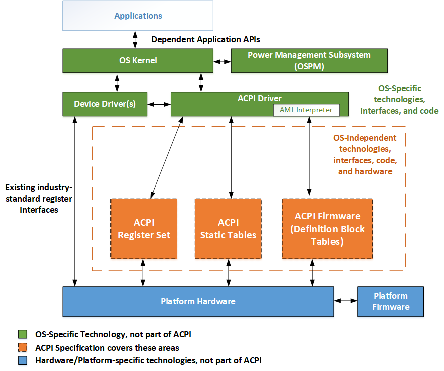
Fig. 1.1 OSPM/ACPI Global System
There are three run-time components to ACPI:
ACPI System Description Tables
Describes the interfaces to the hardware. Some descriptions limit what can be built (for example, some controls are embedded in fixed blocks of registers and the table specifies the address of the register block). Most descriptions allow the hardware to be built in arbitrary ways and can describe arbitrary operation sequences needed to make the hardware function. ACPI Tables containing “Definition Blocks” can make use of a pseudo-code type of language, the interpretation of which is performed by the OS. That is, OSPM contains and uses an interpreter that executes procedures encoded in the pseudo-code language and stored in the ACPI tables containing “Definition Blocks.” The pseudo-code language, known as ACPI Machine Language (AML), is a compact, tokenized, abstract type of machine language.
ACPI Registers
The constrained part of the hardware interface, described (at least in location) by the ACPI System Description Tables.
ACPI Platform Firmware
Refers to the portion of the firmware that is compatible with the ACPI specifications. Typically, this is the code that boots the machine (as legacy BIOSs have done) and implements interfaces for sleep, wake, and some restart operations. It is called rarely, compared to a legacy BIOS. The ACPI Description Tables are also provided by the ACPI Platform Firmware.
1.7. OS and Platform Compliance
The ACPI specification contains only interface specifications. ACPI does not contain any platform compliance requirements. The following sections provide guidelines for class specific platform implementations that reference ACPI-defined interfaces and guidelines for enhancements that operating systems may require to completely support OSPM/ACPI. The minimum feature implementation requirements of an ACPI-compatible OS are also provided.
1.7.1. Platform Implementations of ACPI-defined Interfaces
System platforms implement ACPI-defined hardware interfaces via the platform hardware and ACPI-defined software interfaces and system description tables via the ACPI system firmware. Specific ACPI-defined interfaces and OSPM concepts while appropriate for one class of machine (for example, a mobile system), may not be appropriate for another class of machine (for example, a multi-domain enterprise server). It is beyond the capability and scope of this specification to specify all platform classes and the appropriate ACPI-defined interfaces that should be required for the platform class.
Platform design guide authors are encouraged to require the appropriate ACPI-defined interfaces and hardware requirements suitable to the particular system platform class addressed in a particular design guide. Platform design guides should not define alternative interfaces that provide similar functionality to those defined in the ACPI specification.
1.7.1.1. Recommended Features and Interface Descriptions for Design Guides
Common description text and category names should be used in design guides to describe all features, concepts, and interfaces defined by the ACPI specification as requirements for a platform class. Listed below is the recommended set of high-level text and category names to be used to describe the features, concepts, and interfaces defined by ACPI.
Note
The definitions and relational requirements of the interfaces specified below are generally spread throughout the ACPI specification:
Power or sleep button with S5 override (also possible in generic space)
Real time clock wakeup alarm control/status
SCI /SMI routing control/status for Power Management and General-purpose events
System power state controls (sleeping/wake control)
Processor power state control (c states)
Processor throttling control/status
Processor performance state control/status
General-purpose event control/status
Global Lock control/status
System Reset control
Embedded Controller control/status
SMBus Host Controller (HC) control/status
Smart Battery Subsystem
ACPI-defined Generic Register Interfaces and object definitions in the ACPI Namespace.
General-purpose event processing
Motherboard device identification, configuration, and insertion/removal
Thermal zones
Power resource control
Device power state control
System power state control
System indicators
Devices and device controls:
Processor
Control Method Battery
Smart Battery Subsystem
Mobile Lid
Power or sleep button with S5 override (also possible in fixed space)
Embedded controller
Fan
Generic Bus Bridge
ATA Controller
Floppy Controller
GPE Block
Module
Memory
Global Lock related interfaces
ACPI Event programming model
ACPI-defined Platform Firmware Responsibilities
ACPI-defined State Definitions:
Global system power states (G-states, S0, S5)
System sleeping states (S-states S1-S4)
Device power states (D-states)
Processor power states (C-states)
Device and processor performance states (P-states)
1.7.1.2. Terminology Examples for Design Guides
The following example shows how a client platform design guide could use the recommended terminology to define ACPI requirements, with a goal of requiring robust configuration and power management for the system class.
Note
This example is provided as a guideline for how ACPI terminology can be used. It should not be interpreted as a statement of ACPI requirements.
Platforms compliant with this platform design guide must implement the following ACPI defined system features, concepts, and interfaces, along with their associated event models:
System Address Map Interfaces
ACPI System Description Tables provided in the system firmware
ACPI-defined Fixed Registers Interfaces:
Power management timer control/status
Power or sleep button with S5 override (may also be implemented in generic register space)
Real time clock wakeup alarm control/status
General-purpose event control/status
SCI /SMI routing control/status for Power Management and General-purpose events (control required only if system supports legacy mode)
System power state controls (sleeping/wake control)
Processor power state control (for C1)
Global Lock control/status (if Global Lock interfaces are required by the system)
ACPI-defined Generic Register Interfaces and object definitions in the ACPI Namespace:
General-purpose event processing
Motherboard device identification, configuration, and insertion/removal
System power state control ( Section 7.3)
Devices and device controls:
Processor
Control Method Battery (or Smart Battery Subsystem on a mobile system)
Smart Battery Subsystem (or Control Method Battery on a mobile system)
Power or sleep button with S5 override (may also be implemented in fixed register space)
Global Lock related interfaces when a logical register in the hardware is shared between OS and firmware environments
ACPI Event programming model
ACPI-defined Platform Firmware Responsibilities
ACPI-defined State Definitions:
System sleeping states (At least one system sleeping state, S1-S4, must be implemented)
Device power states (D-states must be implemented in accordance with device class specifications)
Processor power states (All processors must support the C1 Power State)
The following example shows how a design guide could use the recommended terminology to define ACPI related requirements for systems that execute multiple OS instances, with a goal of requiring robust configuration and continuous availability for the system class.
Note
This example is provided as a guideline for how ACPI terminology can be used. It should not be interpreted as a statement of ACPI requirements.
Platforms compliant with this platform design guide must implement the following ACPI defined system features and interfaces, along with their associated event models:
System Address Map Interfaces
ACPI System Description Tables provided in the system firmware
ACPI-defined Fixed Registers Interfaces:
Power management timer control/status
General-purpose event control/status
SCI /SMI routing control/status for Power Management and General-purpose events
(control required only if system supports legacy mode)
System power state controls (sleeping/wake control)
Processor power state control (for C1)
Global Lock control/status (if Global Lock interfaces are required by the system)
ACPI-defined Generic Register Interfaces and object definitions in the ACPI Namespace:
General-purpose event processing
Motherboard device identification, configuration, and insertion/removal (Section 6)
System power state control (Section 7.3)
System indicators
Devices and device controls:
Processor
Global Lock related interfaces when a logical register in the hardware is shared between OS and firmware environments
ACPI Event programming model (Section 5.6)
ACPI-defined Platform Firmware Responsibilities (Section 15)
ACPI-defined State Definitions:
Processor power states (All processors must support the C1 Power State)
1.7.2. OSPM Implementations
OS enhancements are needed to support ACPI-defined features, concepts, and interfaces, along with their associated event models appropriate to the system platform class upon which the OS executes. This is the implementation of OSPM. The following outlines the OS enhancements and elements necessary to support all ACPI-defined interfaces. To support ACPI through the implementation of OSPM, the OS needs to be modified to:
Find and consume the ACPI System Description Tables.
Interpret ACPI machine language (AML).
Enumerate and configure motherboard devices described in the ACPI Namespace.
Interface with the power management timer.
Interface with the real-time clock wake alarm.
Enter ACPI mode (on legacy hardware systems).
Implement device power management policy.
Implement power resource management.
Implement processor power states in the scheduler idle handlers.
Control processor and device performance states.
Implement the ACPI thermal model.
Support the ACPI Event programming model including handling SCI interrupts, managing fixed events, general-purpose events, embedded controller interrupts, and dynamic device support.
Support acquisition and release of the Global Lock.
Use the reset register to reset the system.
Provide APIs to influence power management policy.
Implement driver support for ACPI-defined devices.
Implement APIs supporting the system indicators.
Support all system states S1-S5.
1.7.3. OS Requirements
The following list describes the minimum requirements for an OSPM/ACPI-compatible OS:
Use Section 15 to get the system address map on Intel Architecture (IA) platforms:
INT 15H, E820H - Query System Address Map interface (see Section 15)
EFI GetMemoryMap() Boot Services Function (see Section 15)
Find and consume the ACPI System Description Tables (see Section 5).
Implementation of an AML interpreter supporting all defined AML grammar elements (see Section 20).
Support for the ACPI Event programming model including handling SCI interrupts, managing fixed events, general-purpose events, embedded controller interrupts, and dynamic device support.
Enumerate and configure motherboard devices described in the ACPI Namespace.
Implement support for the following ACPI devices defined within this specification:
Embedded Controller Device (see Section 12)
GPE Block Device (see Section 9.11)
Implementation of the ACPI thermal model (see Section 3.10).
Support acquisition and release of the Global Lock.
OS-directed power management support (device drivers are responsible for maintaining device context as described by the Device Power Management Class Specifications described in
appendix-a).
1.8. Target Audience
This specification is intended for the following users:
OEMs building hardware containing ACPI-compatible interfaces
Operating system and device driver developers
All platform system firmware developers
CPU and chip set vendors
Peripheral vendors
1.9. Document Organization
The ACPI specification document is organized into the following four parts:
The first part of the specification (chapters 1 through 3) introduces ACPI and provides an executive overview.
The second part (chapters 4 and 5) defines the ACPI hardware and software programming models.
The third part (chapters 6 through 17) specifies the ACPI implementation details; this part of the specification is primarily for developers.
The fourth part (chapters 18 and 19) is technical reference material: chapter 18 is the ACPI Source Language (ASL) reference, which is referenced by many other sections in this specification.
Appendices contain device class specifications, describing power management characteristics of specific classes of devices, and device class-specific ACPI interfaces.
1.9.1. ACPI Introduction and Overview
The first three sections of the specification provide an executive overview of ACPI.
- Chapter 1: Introduction
Discusses the purpose and goals of the specification, presents an overview of the ACPI-compatible system architecture, specifies the minimum requirements for an ACPI-compatible system, and provides references to related specifications.
- Chapter 2: Definition of Terms
Defines the key terminology used in this specification. In particular, the global system states (Mechanical Off, Soft Off, Sleeping, Working, and Non-Volatile Sleep) are defined in this Chapter, along with the device power state definitions: Off (D3), D3hot, D2, D1, and Fully-On (D0). Device and processor performance states (P0, P1, …Pn) are also discussed.
- Chapter 3: ACPI Overview
Gives an overview of the ACPI specification in terms of the functional areas covered by the specification: system power management, device power management, processor power management, Plug and Play, handling of system events, battery management, and thermal management.
1.9.2. Programming Models
Chapters 4 and 5 define the ACPI hardware and software programming models. This part of the specification is primarily for system designers, developers, and project managers.
All of the implementation-oriented, reference, and platform example Chapters of the specification that follow (all the rest of the Chapters of the specification) are based on the models defined in Chapters 4 and 5. These Chapters are the heart of the ACPI specification. There are extensive cross-references between the two Chapters.
- Chapter 4: ACPI Hardware Specification
Defines a set of hardware interfaces that meet the goals of this specification.
- Chapter 5: ACPI Software Programming Model
Defines a set of software interfaces that meet the goals of this specification.
1.9.3. Implementation Details
The third part of the specification defines the implementation details necessary to actually build components that work on an ACPI-compatible platform. This part of the specification is primarily for developers.
- Chapter 6: Configuration
Defines the reserved Plug and Play objects used to configure and assign resources to devices, and share resources and the reserved objects used to track device insertion and removal. Also defines the format of ACPI-compatible resource descriptors.
- Chapter 7: Power and Performance Management
Defines the reserved device power-management objects and the reserved-system power-management objects.
- Chapter 8: Processor Configuration and Control
Defines how the OS manages the processors’ power consumption and other controls while the system is in the working state.
- Chapter 9: ACPI-Specific Device Objects
Lists the integrated devices that need support for some device-specific ACPI controls, along with the device-specific ACPI controls that can be provided. Most device objects are controlled through generic objects and control methods and have generic device IDs; this Chapter discusses the exceptions.
- Chapter 10: Power Source Devices
Defines the reserved battery device and AC adapter objects.
- Chapter 11: Thermal Management
Defines the reserved thermal management objects.
- Chapter 12: ACPI Embedded Controller Interface Specification
Defines the interfaces between an ACPI-compatible OS and an embedded controller.
- Chapter 13: ACPI System Management Bus Interface Specification
Defines the interfaces between an ACPI-compatible OS and a System Management Bus (SMBus) host controller.
- Chapter 14: Platform Communications Channel
Explains the generic mechanism for OSPM to communicate with an entity in the platform defines a new address space type.
- Chapter 15: System Address Map Interfaces
Explains the special INT 15 call for use in ISA/EISA/PCI bus-based systems. This call supplies the OS with a clean memory map indicating address ranges that are reserved and ranges that are available on the motherboard. UEFI-based memory address map reporting interfaces are also described.
- Chapter 16: Waking and Sleeping
Defines in detail the transitions between system working and sleeping states and their relationship to wake events. Refers to the reserved objects defined in Chapters 6, 7, and 8.
- Chapter 17: Non-Uniform Memory Access (NUMA) Architecture Platforms
Discusses in detail how ACPI define interfaces can be used to describe a NUMA architecture platform. Refers to the reserved objects defined in Chapters 5, 6, 8, and 9.
- Chapter 18: ACPI Platform Error Interfaces
Defines interfaces that enable OSPM to processes different types of hardware error events that are detected by platform-based error detection hardware.
1.9.4. Technical Reference
The fourth part of the specification contains reference material for developers.
- Chapter 19: ACPI Source Language Reference
Defines the syntax of all the ASL statements that can be used to write ACPI control methods, along with example syntax usage.
- Chapter 20: ACPI Machine Language Specification
Defines the grammar of the language of the ACPI virtual machine language. An ASL translator (compiler) outputs AML.
- Chapter 21: ACPI Data Tables and Table Language Definition
Describes a simple language (the Table Definition Language or TDL) that can be used to generate any ACPI data table.
- Appendix A: Device class specifications
Describes device-specific power management behavior on a per device-class basis.
- Appendix B: Video Extensions
Contains video device class-specific ACPI interfaces
1.9.5. Revsion Numbers
Updates to the ACPI specification are considered either new revisions or errata as described below:
A new revision is produced when there is substantive new content or changes that may modify existing behavior. New revisions are designated by a Major.Minor version number (e.g. 6.3). In cases where the changes are exceptionally minor, we may have a Major.Minor.Minor naming convention (e.g. 6.3.1).
An errata is produced when proposed changes or fixes of the specification do not include any significant new material or modify existing behavior. Errata are designated by adding an upper-case letter at the end of the version number, such as 6.2A.