10. Power Source and Power Meter Devices
This section specifies the battery, AC adapter, and power source device objects OSPM uses to manage power resources, as well as the power meter device objects OSPM uses to measure power consumption.
A battery device is required to either have a Smart Battery subsystem or a Control Method Battery interface as described in this section. OSPM is required to be able to connect and manage a battery on either of these interfaces. This section describes these interfaces.
In the case of a compatible ACPI Smart Battery Table, the Definition Block needs to include a Bus/Device package for the SMB-HC. This will install an OS-specific driver for the SMBus, which in turn will locate the components of the Smart Battery subsystem. In addition to the battery or batteries, the Smart Battery subsystem includes a charger and a manager device to handle subsystems with multiple batteries.
The Smart Battery System Manager is one implementation of a manager device that is capable of arbitrating among the available power sources (AC power and batteries) for a system. It provides a superset of the Smart Battery Selector functionality, such as safely responding to power events (AC versus battery power), inserting and removing batteries and notifying the OS of all such changes. Additionally, the Smart Battery System Manager is capable of handling configurations including simultaneous charging and discharging of multiple batteries. Unlike the Smart Battery Selector that shares responsibility for configuring the battery system with OSPM, the Smart Battery System Manager alone controls the safe configuration of the battery system and simply issues status changes to OSPM when the configuration changes. Smart Battery System Manager is the recommended solution for handling multiple-battery systems.
A Power Meter device is the logical representation of a platform sensor that measures the power consumption of one or more devices in the system. A basic platform implementation implements interfaces that query the current power consumption and get the currently configured power consumption hardware limit, while more advance power meter device implementations provide interfaces that support OSPM configurable power consumption trip points that trigger SCI events, or enable configuration of the underlying hardware to enforce a hard limit on the maximum amount of power that can be consumed.
10.1. Smart Battery Subsystems
The Smart Battery subsystem is defined by the:
System Management Bus Specification (SMBS)
Smart Battery Data Specification (SBDS)
Smart Battery Charger Specification (SBCS)
Smart Battery System Manager Specification (SBSM)
Smart Battery Selector Specification (SBSS)
An ACPI-compatible Smart Battery subsystem consists of:
An SMB-HC (CPU to SMB-HC) interface
At least one Smart Battery
A Smart Battery Charger
Either a Smart Battery System Manager or a Smart Battery Selector if more than one Smart Battery is supported
In such a subsystem, a standard way of communicating with a Smart Battery and Smart Battery Charger is through the SMBus physical protocols. The Smart Battery System Manager or Smart Battery Selector provides event notification (battery insertion/removal, and so on) and charger SMBus routing capability for any Smart Battery subsystem. A typical Smart Battery subsystem is illustrated below:
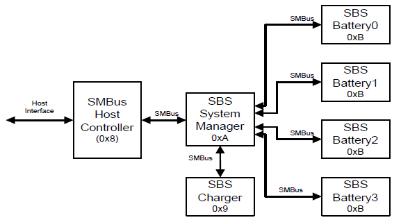
Fig. 10.1 Typical Smart Battery Subsystem (SBS)
SMBus defines a fixed 7-bit slave address per device. This means that all batteries in the system have the same address (defined to be 0xB). The slave addresses associated with Smart Battery subsystem components are shown in the following table.
SMBus Device Description |
SMBus Slave Address (A0-A6) |
|---|---|
SMBus Host Slave Interface |
0x8 |
Smart Battery Charger/Charger Selector or Charger System Manager |
0x9 |
Smart Battery System Manager or Smart Battery Selector |
0xA |
Smart Battery |
0xB |
Each SMBus device has up to 256 registers that are addressed through the SMBus protocol’s Command value. SMBus devices are addressed by providing the slave address with the desired register’s Command value. Each SMBus register can have non-linear registers; that is, command register 1 can have a 32-byte string, while command register 2 can have a byte, and command register 3 can have a word.
The SMBus host slave interface provides a standard mechanism for the host CPU to generate SMBus protocol commands that are required to communicate with SMBus devices (in other words, the Smart Battery components). ACPI defines such an SMB-HC that resides in embedded controller address space; however, an OS can support any SMB-HC that has a native SMB-HC device driver.
Event notification for battery insertion and removal
Event notification for AC power connected or disconnected
Status of which Smart Battery is communicating with the SMB-HC
Status of which Smart Battery(s) are powering the system
Status of which Smart Battery(s) are connected to the charger
Status of which Smart Batteries are present in the system
Event notification when the Smart Battery System Manager switches from one power source to another
Hardware-switching to an alternate Smart Battery when the Smart Battery supplying power runs low
Hardware switching between battery-powered and AC-powered powered operation
The Smart Battery System Manager function can reside in a standalone SMBus slave device (Smart Battery System Manager that responds to the 0xA slave address), may be present within a smart charger device (Smart Battery Charger that responds to the 0x9 slave address), or may be combined within the embedded controller (that responds to the 0xA slave address). If both a Smart Battery Charger and a standalone Smart Battery System Manager are present in the same Smart Battery subsystem, then the driver assumes that the standalone Smart Battery System Manager is wired to the batteries.
The Smart Battery charger is an SMBus device that provides a standard programming model to control the charging of Smart Batteries present in a Smart Battery subsystem. For single battery systems, the Smart Battery Charger is also responsible for notifying the system of the battery and AC status.
The Smart Battery provides intelligent chemistry-independent power to the system. The Smart Battery is capable of informing the Smart Battery charger of its charging requirements (which provides chemistry independence) and providing battery status and alarm features needed for platform battery management.
10.1.1. ACPI Smart Battery Status Change Notification Requirements
The Smart Battery System Manager, the Smart Battery Selector, and the Smart Battery Charger each have an optional mechanism for notifying the system that the battery configuration or AC status has changed. ACPI requires that this interrupt mechanism be through the SMBus Alarm Notify mechanism.
For systems using an embedded controller as the SMBus host, a battery system device issues a status change notification by either mastering the SMBus to send the notification directly to the SMBus host, or by emulating it in the embedded controller. In either case, the process is the same. After the notification is received or emulated, the embedded controller asserts an SCI. The source of the SCI is identified by a GPE that indicates the SCI was caused by the embedded controller. The embedded controller’s status register alarm bit is set, indicating that the SMBus host received an alarm message. The Alarm Address Register contains the address of the SMBus device that originated the alarm and the Alarm Data Registers contain the contents of that device’s status register.
10.1.1.1. Smart Battery Charger
This requires a Smart Battery Charger, on a battery or AC status change, to generate an SMBus Alarm Notify. The contents of the Smart Battery Charger’s ChargerStatus() command register (0x13) is placed in the embedded controller’s Alarm Data Registers, the Smart Battery Charger’s slave address (See Note Below) (0x09) is placed in the embedded controller’s Alarm Address Register and the EC’s Status Register’s Alarm bit is set. The embedded controller then asserts an SCI.
Note
The 1.0 SMBus protocol specification is ambiguous about the definition of the “slave address” written into the command field of the host controller. In this case, the slave address is actually the combination of the 7-bit slave address and the Write protocol bit. Therefore, bit 0 of the initiating device’s slave address is aligned to bit 1 of the host controller’s slave command register, bit 1 of the slave address is aligned to bit 2 of the controller’s slave command register, and so on.
10.1.1.2. Smart Battery Charger with optional System Manager or Selector
A Smart Battery Charger that contains the optional System Manager or Selector function (as indicated by the ChargerSpecInfo() command register, 0x11, bit 4) is required to generate an SMBus Alarm Notify on a battery or AC status change. The content of the Smart Battery Charger with an optional System Manager, the BatterySystemState() command register (0x21) (or in the case of an optional Selector, the SelectorState() (0x01) ), is placed in the EC’s Alarm Data Registers, the Smart Battery Charger’s slave address (0x09) is placed in the embedded controller’s Alarm Address Register, and the embedded controller’s Status Register’s Alarm bit is set. The embedded controller then asserts an SCI.
10.1.1.3. Smart Battery System Manager
The Smart Battery System Manager is required to generate an SMBus Alarm Notify on a battery or AC status change. The content of the Smart Battery System Manager’s BatterySystemState() command register (0x01) is placed in the EC’s Alarm Data Registers, the Smart Battery System Manager’s slave address (0x0A) is placed in the EC’s Alarm Address Register, and the embedded controller’s Status Register’s Alarm bit is set. The embedded controller then asserts an SCI.
10.1.1.4. Smart Battery Selector
The requirements for the Smart Battery Selector are the same as the requirements for the Smart Battery System Manager, with the exception that the contents of the SelectorState() command register (0x01) are used instead of BatterySystemState(). The Smart Battery Selector is a subset of the Smart Battery System Manager and does not have the added support for simultaneous charge/discharge of multiple batteries. The System Manager is the preferred implementation.
10.1.2. Smart Battery Objects
The Smart Battery subsystem requires a number of objects to define its interface. These are summarized below:
Object |
Description |
|---|---|
_HID |
This is the hardware ID named object that contains a string. For Smart Battery subsystems, this object returns the value of “ACPI0002.” This identifies the Smart Battery subsystem to the Smart Battery driver. |
_SBS |
This is the Smart Battery named object that contains a DWORD. This named object returns the configuration of the Smart Battery. |
10.1.3. _SBS (Smart Battery Subsystem)
The _SBS control method returns the configuration of the Smart Battery subsystem. This named object returns a DWORD value with a number from 0 to 4. If the number of batteries is greater than 0, then the Smart Battery driver assumes that a Smart Battery System Manager or Smart Battery Selector is present. If 0, then the Smart Battery driver assumes a single Smart Battery and neither a Smart Battery System Manager nor Smart Battery Selector is present.
Arguments:
None
Return Value:
The DWORD returned by _SBS is an Integer containing the Smart Battery subsystem configuration:
0 - Maximum of one Smart Battery and no Smart Battery System Manager or Smart Battery Selector.
1 - Maximum of one Smart Battery and a Smart Battery System Manager or Smart Battery Selector.
2 - Maximum of two Smart Batteries and a Smart Battery System Manager or Smart Battery Selector.
3 - Maximum of three Smart Batteries and a Smart Battery System Manager or Smart Battery Selector.
4 - Maximum of four Smart Batteries and a Smart Battery System Manager or Smart Battery Selector.
The maximum number of batteries is for the entire system. Therefore, if the platform is capable of supporting four batteries, but only two are normally present in the system, then this field should return 4. Notice that a value of 0 indicates a maximum support of one battery and there is no Smart Battery System Manager or Smart Battery Selector present in the system
As the SMBus is not an enumerable bus, all devices on the bus must be declared in the ACPI name-space. As the Smart Battery driver understands Smart Battery, Smart Battery Charger, and Smart Battery System Manager or Smart Battery Selector; only a single device needs to be declared per Smart Battery subsystem. The driver gets information about the subsystem through the hardware ID (which defines a Smart Battery subsystem) and the number of Smart Batteries supported on this subsystem (_SBS named object). The ACPI Smart Battery table indicates the energy levels of the platform at which the system should warn the user and then enter a sleeping state. The Smart Battery driver then reflects these as threshold alarms for the Smart Batteries.
A Smart Battery device declaration in the ACPI namespace requires the _GLK object if potentially contentious accesses to device resources are performed by non-OS code. See _GLK (Global Lock) for details about the _GLK object.
10.1.3.1. Example: Single Smart Battery Subsystem
This section illustrates how to define a Smart Battery subsystem containing a single Smart Battery and charger. The platform implementation is illustrated below:
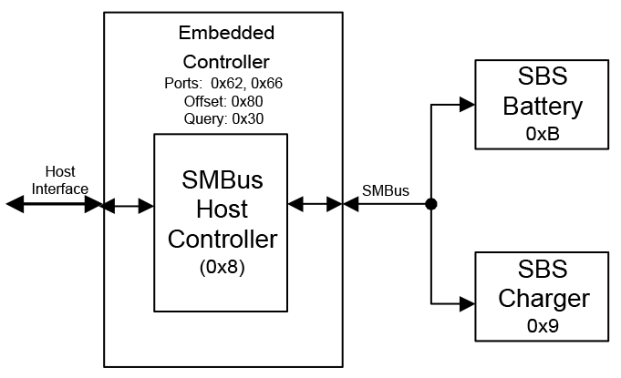
Fig. 10.2 Single Smart Battery Subsystem
In this example, the platform is using an SMB-HC that resides within the embedded controller and meets the ACPI standard for an embedded controller interface and SMB-HC interface. The embedded controller interface sits at system I/O port addresses 0x62 and 0x66. The SMB-HC is at base address 0x80 within embedded controller address space (as defined by the ACPI embedded controller specification) and responds to events on query value 0x30.
In this example the Smart Battery subsystem only supports a single Smart Battery. The ASL code for describing this interface is shown below:
Device (EC0) {
   Name (_HID, EISAID("PNP0C09"))
   Name (_CRS,
      ResourceTemplate () {                // port 0x62 and 0x66
         IO (Decode16, 0x62, 0x62, 0, 1),
         IO (Decode16, 0x66, 0x66, 0, 1)
      }
   )
   Name (_GPE, 0)
   Device (SMB0) {
      Name (_HID, "ACPI0001")              // Smart Battery Host Controller
      Name (_EC, 0x8030)                   // EC offset (0x80), Query (0x30)
      Device (SBS0){                       // Smart Battery Subsystem
         Name (_HID, "ACPI0002")           // Smart Battery Subsystem ID
         Name(_SBS, 0x1)                   // Indicates support for one battery
      }                                    // end of SBS0
   }                                       // end of SMB0
}                                          // end of EC
10.1.3.2. Multiple Smart Battery Subsystem: Example
This section illustrates how to define a Smart Battery subsystem that contains three Smart Batteries, a Smart Battery System Manager, and a Smart Battery Charger. The platform implementation is illustrated below:
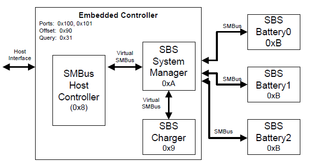
Fig. 10.3 Smart Battery Subsystem
In this example, the platform is using an SMB-HC that resides within the embedded controller and meets the ACPI standard for an embedded controller interface and SMB-HC interface. The embedded controller interface sits at system I/O port addresses 0x100 and 0x101. The SMB-HC resides at base address 0x90 within embedded controller address space (as defined by the ACPI embedded controller specification) and responds to events on query value 0x31.
In this example the Smart Battery subsystem supports three Smart Batteries. The Smart Battery Charger and Smart Battery System Manager reside within the embedded controller, meet the Smart Battery System Manager and Smart Battery Charger interface specification, and respond to their 7-bit addresses (0xA and 0x9 respectively). The ASL code for describing this interface is shown below:
Device (EC1) {

Name (_HID, EISAID("PNP0C09"))
   Name (_CRS,
      ResourceTemplate () {             // port 0x100 and 0x101
         IO(Decode16, 0x100, 0x100, 0, 2)
      }
   )
   Name (_GPE, 1)
   Device (SMB1) {
      Name (_HID, "ACPI0001")           // Smart Battery Host Controller
      Name (_EC, 0x9031)                // EC offset (0x90), Query (0x31)
      Device (SBS1){                    // Smart Battery Subsystem
         Name (_HID, "ACPI0002")        // Smart Battery Subsystem ID
         Name (_SBS, 0x3)               // Indicates support for three batteries
      }                                 // end of SBS1
   }                                    // end of SMB1
}                                       // end of EC
10.2. Control Method Batteries
The following section illustrates the operation and definition of the Control Method Battery.
The Hardware ID for a Control Method Battery is PNP0C0A.
10.2.1. Battery Events
The AML code handling an SCI for a battery event notifies the system of which battery’s status may have changed. The OS uses the _BST control method to determine the current status of the batteries and what action, if any, should be taken (for more information about the _BST control method, see Battery Control Methods ). The typical action is to notify applications monitoring the battery status to provide the user with an up-to-date display of the system battery state. But in some cases, the action may involve generating an alert or even forcing a system into a sleeping state. In any case, any changes in battery status should generate an SCI in a timely manner to keep the system power state UI consistent with the actual state of the system battery (or batteries).
Unlike most other devices, when a battery is inserted or removed from the system, the device itself (the battery bay) is still considered to be present in the system. For most systems, the _STA for this device will always return a value with bits 0-3 set and will toggle bit 4 to indicate the actual presence of a battery (see Section 7.2.4 ). When this insertion or removal occurs, the AML code handler for this event should issue a Notify(battery_device, 0x81) to indicate that the static battery information has changed. For systems that have battery slots in a docking station or batteries that cannot be surprise-removed, it may be beneficial or necessary to indicate that the entire device has been removed. In this case, the standard methods and notifications described in Device Insertion, Removal, and Status Objects should be used.
When the present state of the battery has changed or when the trip point set by the _BTP control method is reached or crossed, the hardware will assert a general purpose event. The AML code handler for this event issues a Notify(battery_device, 0x80) on the battery device. This notification is also sent when the Status Flags returned from _BMD change.
In the case where the remaining battery capacity becomes critically low, the AML code handler issues a Notify(battery_device, 0x80) and reports the battery critical flag in the _BST object. The OS performs an emergency shutdown. For a full description of the critical battery state, see Low Battery Levels.
Sometimes the value to be returned from _BST or _BIF will be temporarily unknown. In this case, the method may return the value 0xFFFFFFFF as a placeholder. When the value becomes known, the appropriate notification (0x80 for _BST or 0x81 for BIF) should be issued, in like manner to any other change in the data returned by these methods. This will cause OSPM to re-evaluate the method–obtaining the correct data value.
When one or more of the status flags returned by the _BMD control method change, AML code issues a Notify(battery_device, 0x82) on the battery device unless this change occurs during a call to _BMC and the value of the status flags in _BMD match the value passed in to _BMC. If the value of the status bits cannot be set to reflect the action requested by the executing _BMC, the AML code will issue this notification. For example, calling _BMC with bit 0 set to initiate a calibration cycle while AC power is not available will cause AML to issue a Notify(battery_device, 0x82).
A user can program peak power delivery thresholds in the _BPT control method for each battery. When a threshold is crossed, the platform firmware such as the embedded controller will assert an SCI interrupt. The AML event handler for this interrupt issues a Notify(<battery_device>, 0x83) on the battery device.
10.2.2. Battery Control Methods
The Control Method Battery is a battery with an AML code interface between the battery and the host PC. The battery interface is completely accessed by AML code control methods, allowing the OEM to use any type of battery and any kind of communication interface supported by ACPI. OSPM requires accurate battery data to perform optimal power management policy and to provide the end user with a meaningful estimation of remaining battery life. As such, control methods that return battery information should calculate this information rather than return hard coded data.
A Control Method Battery is described as a device object. Each device object supporting the Control Method Battery interface contains the following additional control methods. When there are two or more batteries in the system, each battery will have an independent device object in the namespace.
Object |
Description |
|---|---|
_BCT |
Returns battery estimated charging time. |
_BIF |
Returns static information about a battery (in other words, model number, serial number, design voltage, and so on). |
_BIX |
Returns extended static information about a battery (in other words, model number, serial number, design voltage, and so on). |
_BMA |
Sets the averaging interval of the battery capacity measurement, in milliseconds. |
_BMC |
Control calibration and charging. |
_BMD |
Returns battery information related to battery recalibration and charging control. |
_BMS |
Sets the sampling time of the battery capacity measurement, in milliseconds. |
_BPC |
Returns static variables that are associated with system power characteristics on the battery path and power threshold support settings. |
_BPS |
Returns the power delivery capabilities of the battery at the present time. |
_BPT |
Control method to set a Battery Power Threshold. |
_BST |
Returns the current battery status (in other words, dynamic information about the battery, such as whether the battery is currently charging or discharging, an estimate of the remaining battery capacity, and so on). |
_BTH |
Communicates battery thermal throttle limit set by battery thermal zone. |
_BTM |
Returns battery estimated runtime at the present average rate of drain, or the runtime at a specified rate. |
_BTP |
Sets the Battery Trip point, which generates an SCI when batterycapacity reaches the specified point. |
_OSC |
OSPM Capabilities conveyance for batteries. |
_PCL |
List of pointers to the device objects representing devices powered by the battery - see Section 10.3.2 |
_STA |
Returns general status of the battery - see Section 6.3.7. |
A Control Method Battery device declaration in the ACPI namespace requires the _GLK object if potentially contentious accesses to device resources are performed by non-OS code. See _GLK (Global Lock) for details about the _GLK object.
10.2.2.1. _BCT (Battery Charge Time)
When the battery is charging, this optional object returns the estimated time from present to when it is charged to a given percentage of Last Full Charge Capacity.
Arguments:
Arg0 - ChargeLevel (Integer (DWORD)): The queried charge level in units of percent of Last Full Charge Capacity. For example: 96 refers to 96% of Last Full Charge Capacity. Valid values are 1 - 100 (0x00000001 - 0x00000064).
Return Value:
An Integer (DWORD) containing a result code as follows:
0x00000000 - Specified targeted charging capacity is smaller than the current remaining capacity or larger than 100% of Last Full Charge Capacity. 0x00000001 - 0xFFFFFFFE - Estimated charging time in seconds 0xFFFFFFFF - Charging time is unknown
10.2.2.2. _BIF (Battery Information)
This object returns the static portion of the Control Method Battery information. This information remains constant until the battery is changed. This object is deprecated in ACPI 4.0. The _BIX object provides expanded battery information and includes all of the information provide by _BIF. See _BIX (Battery Information Extended) ).
Arguments:
None
Return Value:
A Package containing the battery information as described below.
Return Value Information:
_BIF returns a package in the format shown below:
Package {
   Power Unit                       // Integer (DWORD)
   Design Capacity                  // Integer (DWORD)
   Last Full Charge Capacity        // Integer (DWORD)
   Battery Technology               // Integer (DWORD)
   Design Voltage                   // Integer (DWORD)
   Design Capacity of Warning       // Integer (DWORD)
   Design Capacity of Low           // Integer (DWORD)
   Battery Capacity Granularity 1   // Integer (DWORD)
   Battery Capacity Granularity 2   // Integer (DWORD)
   Model Number                     // String (ASCIIZ)
   Serial Number                    // String (ASCIIZ)
   Battery Type                     // String (ASCIIZ)
   OEM Information                  // String (ASCIIZ)
}
Field |
Format |
Description |
|---|---|---|
Power Unit |
Integer (DWORD) |
Indicates the units used by the battery to report its capacity and charge/discharge rate information to the OS.
0x00000000 - Capacity information is reported in [mWh] and charge/discharge rate information in [mW].
0x00000001 - Capacity information is reported in [mAh] and charge/discharge rate information in [mA].
|
Design Capacity |
Integer (DWORD) |
Battery’s design capacity. Design Capacity is the nominal capacity of a new battery. The Design Capacity value is expressed as power [mWh] or current [mAh] depending on the Power Unit value.
0x000000000 - 0x7FFFFFFF (in [mWh] or [mAh] )
0xFFFFFFFF - Unknown design capacity
|
Last Full Charge Capacity |
Integer (DWORD) |
Predicted battery capacity when fully charged. The Last Full Charge Capacity value is expressed as power (mWh) or current (mAh) depending on the Power Unit value.
0x000000000h - 0x7FFFFFFF (in [mWh] or [mAh] )
0xFFFFFFFF - Unknown last full charge capacity
|
Battery Technology |
Integer (DWORD) |
0x00000000 - Primary (for example, non-rechargeable)
0x00000001 - Secondary (for example, rechargeable)
|
Design Voltage |
Integer (DWORD) |
Nominal voltage of a new battery.
0x000000000 - 0x7FFFFFFF in [mV]
0xFFFFFFFF - Unknown design voltage
|
Design capacity of Warning |
Integer (DWORD) |
OEM-designed battery warning capacity. See Low Battery Levels
0x000000000 - 0x7FFFFFFF in [mWh] or [mAh]
|
Design Capacity of Low |
Integer (DWORD) |
OEM-designed low battery capacity. See Low Battery Levels
0x000000000 - 0x7FFFFFFF in [mWh] or [mAh]
|
Battery Capacity Granularity 1 |
Integer (DWORD) |
Battery capacity granularity between low and warning in [mAh] or [mWh]. That is, this is the smallest increment in capacity that the battery is capable of measuring. See note below for more details |
Battery Capacity Granularity 2 |
Integer (DWORD) |
Battery capacity granularity between warning and Full in [mAh] or [mWh]. That is, this is the smallest increment in capacity that the battery is capable of measuring. This may be a different value than Battery Capacity Granularity 1 to accommodate systems where the granularity accuracy may change depending on the battery level. See note below for more details. |
Model Number |
String (ASCIIZ) |
OEM-specific Control Method Battery model number |
Serial Number |
String (ASCIIZ) |
OEM-specific Control Method Battery serial number |
Battery Type |
String (ASCIIZ) |
The OEM-specific Control Method Battery type |
OEM Information |
String (ASCIIZ) |
OEM-specific information for the battery that the UI uses to display the OEM information about the Battery. If the OEM does not support this information, this field should contain a NULL string. |
Additional Notes:
A secondary-type battery should report the corresponding capacity (except for Unknown).
On a multiple-battery system, all batteries in the system should return the same granularity.
Operating systems prefer these control methods to report data in terms of power (watts).
On a multiple-battery system, all batteries in the system must use the same power unit.
The definition of battery capacity granularity has been clarified. For OSPM to determine if systems support the clarified definition of battery capacity granularity, OSPM may evaluate an _OSC method at
the battery scope to indicate support for this capability, and for the platform to indicate if it supports these extended capabilities.
10.2.2.3. _BIX (Battery Information Extended)
The _BIX object returns the static portion of the Control Method Battery information. This information remains constant until the battery is changed. The _BIX object returns all information available via the _BIF object plus additional battery information. The _BIF object is deprecated in lieu of _BIX in ACPI 4.0.
Arguments:
None
Return Value:
A Package containing the battery information as described below
Return Value Information:
_BIX returns a package in the format below.
Package {
   // ASCIIZ is ASCII character string terminated with a 0x00.
   Revision                            //Integer
   Power Unit                          //Integer (DWORD)
   Design Capacity                     //Integer (DWORD)
   Last Full Charge Capacity           //Integer (DWORD)
   Battery Technology                  //Integer (DWORD)
   Design Voltage                      //Integer (DWORD)
   Design Capacity of Warning          //Integer (DWORD)
   Design Capacity of Low              //Integer (DWORD)
   Cycle Count                         //Integer (DWORD)
   Measurement Accuracy                //Integer (DWORD)
   Max Sampling Time                   //Integer (DWORD)
   Min Sampling Time                   //Integer (DWORD)
   Max Averaging Interval              //Integer (DWORD)
   Min Averaging Interval              //Integer (DWORD)
   Battery Capacity Granularity 1      //Integer (DWORD)
   Battery Capacity Granularity 2      //Integer (DWORD)
   Model Number                        //String (ASCIIZ)
   Serial Number                       //String (ASCIIZ)
   Battery Type                        //String (ASCIIZ)
   OEM Information                     //String (ASCIIZ)
   Battery Swapping Capability         //Integer (DWORD)
}
Field |
Format |
Description |
|---|---|---|
Revision |
Integer |
Current revision is: 1 |
Power Unit |
Integer (DWORD) |
Indicates the units used by the battery to report its capacity and charge/discharge rate information to the OS.
0x00000000 - Capacity information is reported in [mWh] and charge/discharge rate information in [mW].
0x00000001 - Capacity information is reported in [mAh] and charge/discharge rate information in [mA].
|
Design Capacity |
Integer (DWORD) |
Battery’s design capacity. Design Capacity is the nominal capacity of a new battery. The Design Capacity value is expressed as power [mWh] or current [mAh] depending on the Power Unit value.
0x000000000 - 0x7FFFFFFF (in [mWh] or [mAh] )
0xFFFFFFFF - Unknown design capacity
|
Last Full Charge Capacity |
Integer (DWORD) |
Predicted battery capacity when fully charged. The Last Full Charge Capacity value is expressed as power (mWh) or current (mAh) depending on the Power Unit value.
0x000000000h - 0x7FFFFFFF (in [mWh] or [mAh])
0xFFFFFFFF - Unknown last full charge capacity
|
Battery Technology |
Integer (DWORD) |
0x00000000 - Primary (for example, non-rechargeable)
0x00000001 - Secondary (for example, rechargeable)
|
Design Voltage |
Integer (DWORD) |
Nominal voltage of a new battery.
0x000000000 - 0x7FFFFFFF in [mV]
0xFFFFFFFF - Unknown design voltage
|
Design capacity of Warning |
Integer (DWORD) |
OEM-designed battery warning capacity. See Low Battery Levels
0x000000000 - 0x7FFFFFFF in [mWh] or [mAh]
|
Design Capacity of Low |
Integer (DWORD) |
OEM-designed low battery capacity. See Low Battery Levels
0x000000000 - 0x7FFFFFFF in [mWh] or [mAh]
|
Cycle Count |
Integer (DWORD) |
The number of cycles the battery has experienced. A cycle is defined as: An amount of discharge approximately equal to the value of Design Capacity.
0x000000000 - 0xFFFFFFFE
0xFFFFFFFF - Unknown cycle count
|
Measurement Accuracy |
Integer (DWORD) |
The accuracy of the battery capacity measurement, in thousandth of a percent. (0% - 100.000%) For example, The value 80000 would mean 80% accuracy. |
Max Sampling Time |
Integer (DWORD) |
The sampling time is the duration between two consecutive measurements of the battery’s capacities specified in _BST, such as present rate and remaining capacity. If the OSPM makes two succeeding readings through _BST beyond the duration, two different results will be returned. The Max Sampling Time is the maximum sampling time the battery can support, in milliseconds. 0xFFFFFFFF is returned if the information is unavailable. |
Min Sampling Time |
Integer (DWORD) |
The Min Sampling Time is the minimum sampling time the battery can support, in milliseconds. 0xFFFFFFFF is returned if the information is unavailable. |
Max Averaging Interval |
Integer (DWORD) |
The Average Interval is the length of time (in milliseconds) within which the battery averages the capacity measurements specified in _BST, such as remaining capacity and present rate. The Sampling time specifies the frequency of measurements, and the average interval specifies the width of the time window of every measurement. This field indicates the maximum Average Interval that the battery supports. |
Min Averaging Interval |
Integer (DWORD) |
This field indicates the minimum Average Interval that the battery supports |
Battery Capacity Granularity 1 |
Integer (DWORD) |
Battery capacity granularity between low and warning in [mAh] or [mWh]. That is, this is the smallest increment in capacity that the battery is capable of measuring. See note below for more details |
Battery Capacity Granularity 2 |
Integer (DWORD) |
Battery capacity granularity between warning and Full in [mAh] or [mWh]. That is, this is the smallest increment in capacity that the battery is capable of measuring. This may be a different value than Battery Capacity Granularity 1 to accommodate systems where the granularity accuracy may change depending on the battery level. See note below for more details. |
Model Number |
String (ASCIIZ) |
OEM-specific Control Method Battery model number |
Serial Number |
String (ASCIIZ) |
OEM-specific Control Method Battery serial number |
Battery Type |
String (ASCIIZ) |
The OEM-specific Control Method Battery type |
OEM Information |
String (ASCIIZ) |
OEM-specific information for the battery that the UI uses to display the OEM information about the Battery. If the OEM does not support this information, this field should contain a NULL string. |
Battery Swapping Capability |
Integer (DWORD) |
0x00000000 Non swappable battery (for example, sealed internal battery not accessible to user)
0x00000001 Cold swappable battery, i.e. batteries that require system to be shut down in order to replace the battery while on DC power (for example, phone and laptop batteries accessible to user)
0x00000010 Hot swappable battery, i.e. batteries that do not require the system to be shut down in order to replace/remove the battery while on DC power (for example, accessory batteries, cd tray batteries, external batteries, dock batteries, keyboard batteries)
|
Note
A secondary-type battery should report the corresponding capacity (except for Unknown).
On a multiple-battery system, all batteries in the system should return the same granularity.
Operating systems prefer these control methods to report data in terms of power (watts).
On a multiple-battery system, all batteries in the system must use the same power unit.
The definition of battery capacity granularity has been clarified. For OSPM to determine if systems support the clarified definition of battery capacity granularity, OSPM may evaluate an _OSC method at the battery scope to indicate support for this capability, and for the platform to indicate if it supports these extended capabilities.
10.2.2.4. _BMA (Battery Measurement Averaging Interval)
This object is used to set the averaging interval of the battery capacity measurement, in milliseconds. The Battery Measurement Averaging Interval is the length of time within which the battery averages the capacity measurements specified in _BST, such as remaining capacity and present rate.
The OSPM may read the Max Average Interval and Min Average Interval with _BIX during boot time, and set a specific average interval within the range with _BMA.
Arguments:(1)
Arg0 - AveragingInterval (Integer(DWORD)) the averaging interval of battery capacity measurement:
0x00000001 - 0xFFFFFFFF (in units of millisecond)
Return Value:
An Integer (DWORD) containing a result code as follows:
0x00000000 - Success.
0x00000001 - Failure to set Battery Measurement Averaging Interval because it is out of the battery’s measurement capability.
0x00000002 - 0xFFFFFFFF - Reserved.
10.2.2.5. _BMC (Battery Maintenance Control)
This object is used to initiate calibration cycles or to control the charger and whether or not a battery is powering the system. This object is only present under a battery device if the _BMD Capabilities Flags field has bit 0, 1, 2, or 5 set.
Arguments:(1)
Arg0 - An Integer containing feature control flags:
Bit [0] - Set to initiate an AML controlled calibration cycle. Clear to end the calibration cycle
Bit [1] - Set to disable charging. Clear to enable charging
Bit [2] - Set to allow the battery to discharge while AC power is available. Clear to prevent discharging while AC power is available
Bit [3] – Set to request suspension of Battery Charge Limiting mode
Return Value:
None
See Battery Calibration for more information.
Evaluating this object with bit0 set will initiate an AML controlled recalibration cycle if _BMD indicates that this is supported. The calibration cycle is controlled by the platform and will typically include disabling the AC adapter and discharging the battery, then charging the battery. While the battery is charging, the platform runtime firmware should set Bit [4] of the Status flags returned by _BMD if it is possible to put the system into standby during calibration to speed up charging. Evaluating this with Bit [0] equal to 0 will abort the calibration cycle if one is in process. If the platform runtime firmware determines that the calibration cycle must be aborted (for example AC power is lost), or the calibration completes successfully, the platform runtime firmware will end the cycle automatically, clear the _BMD Status Flag Bit [0], and send a notify 0x82. While the calibration cycle is in process, the battery will report data normally, so the OS must disable battery alarms.
Bit [1], Bit [2], and Bit [3] may not be used in conjunction with the AML controlled calibration cycle. Having Bit [0] set will override Bit [1], Bit [2], and Bit [3]. Bit [1] will prevent the battery from charging even though AC power is connected. Bit [2] will allow the system to draw its power from the battery even though AC power is available. When the battery is no longer capable of delivering current, this setting is automatically cleared, and the system will continue running off AC power without interruption. In addition, if AC power is lost this bit will be cleared. When AC power comes back, the OS must set the bit again if the user wants to continue discharging. When the system clears this bit automatically, it will result in a change in the Status Flags returned by _BMD. This will cause a notify 0x82. Bit [1] is only cleared automatically if an AML controlled calibration cycle is initiated.
When a battery is discharging because Bit [2] is set, the _PSR method of the AC adapter device will report that AC is offline because the system is not running off of the AC adapter. If the batteries are controlled individually (Bit [3] of the _BMD Capabilities Flags), setting either battery to discharge will cause _PSR to report AC offline. If more than one battery in the system has Bit [2] set to discharge the battery, it is up to the system to decide which battery to discharge, so only on a system that discharges the batteries one at a time, a battery with Bit2 set may not be discharging if another battery in the system is being discharged.
If Batteries are not controlled individually, calling _BMC will initiate calibration, disable charge, and/or allow discharge on all batteries in the system. The state of these batteries will be reflected in the _BMD Status Flags for all batteries.
Bit [3] is set to request temporary suspension of Battery Charge Limiting. This bit may not be set unless Bit [6] of the _BMD Capabilities Flags is also set.
10.2.2.6. _BMD (Battery Maintenance Data)
This optional object returns information about the battery’s capabilities and current state in relation to battery calibration and charger control features. If the _BMC object (defined below) is present under a battery device, this object must also be present. Whenever the Status Flags value changes, AML code will issue a Notify(battery_device, 0x82). In addition, AML will issue a Notify(battery_device, 0x82) if evaluating _BMC did not result in causing the Status Flags to be set as indicated in that argument to _BMC. AML is not required to issue Notify(battery_device, 0x82) if the Status Flags change while evaluating _BMC unless the change does not correspond to the argument passed to _BMC.
Arguments:
None
Return Value:
A Package containing the battery maintenance data as described below
Return Value Information:
_BMD returns a package in the format below:
Package {
   Status Flags                                   // Integer (DWORD)
   Capability Flags                               // Integer (DWORD)
   Recalibrate Count                              // Integer (DWORD)
   Quick Recalibrate Time                         // Integer (DWORD)
   Slow Recalibrate Time                          // Integer (DWORD)
}
Field |
Format |
Description |
|---|---|---|
Status Flags |
Integer (DWORD) |
Bit values.
Bit [0] is mutually exclusive with bit [1] and bit [2]. If the charger is being manually controlled, there cannot be an AML controlled calibration cycle.
Bit[0] - 1 indicates the battery is running an AML controlled calibration cycle
Bit[1] - 1 indicates that charging has been disabled.
Bit[2] - 1 indicates the battery is configured to discharge while AC power is available.
Bit[3] - 1 indicates that the battery should be recalibrated.
Bit[4] - 1 indicates that the OS should put the system into standby to speed charging during a calibration cycle. This is optional (based on user preference) if “Slow Recalibrate Time” is not equal to 0x00000000.
Bit[5] – 1 indicates that Battery Charge Limiting cannot be suspended due to Thermal Conditions.
Bit[6] – 1 indicates that Battery Charge Limiting cannot be suspended for Battery Protection reasons.
Bit [31:7] - reserved.
|
Capability Flags |
Integer (DWORD) |
Bit values that describe the capabilities of the battery system. These bits allows a battery system with more limited capabilities to still be calibrated by OSPM.
Bit[0] - 1 indicates that an AML controlled calibration cycle is supported.
Bit[1] - 1 indicates that disabling the charger is supported.
Bit[2] - 1 indicates that discharging while running on AC is supported.
Bit[3] - 1 indicates that calling _BMC for one battery will affect the state of all batteries in the system. This is for battery systems that cannot control batteries individually.
Bit[4] - 1 indicates that calibration should be done by first fully charging the battery and then discharging it. Not setting this bit will indicate that calibration can be done by simply discharging the battery.
Bit[5] – 1 indicates that Battery Charge Limiting suspension is supported.
Bits[31:6] - Reserved
|
Recalibrate Count |
Integer (DWORD) |
This is used by battery systems that can’t detect when calibration is required, but wish to recommend that the battery should be calibrated after a certain number of cycles. Counting the number of cycles and partial cycles is done by the OS.
0x00000000 - Only calibrate when Status Flag bit [3] is set.
0x00000000-0xFFFFFFFF - calibrate battery after detecting this many battery cycles.
|
Quick Recalibrate Time |
Integer (DWORD) |
Returns the estimated time it will take to calibrate the battery if the system is put into standby whenever Status Flags bit [4] is set. While the AML controlled calibration cycle is in progress, this returns the remaining time in the calibration cycle.
0x000000000 - indicates that standby while calibrating the battery is not supported. The system should remain in S0 until calibration is completed.
0x00000001 - 0xFFFFFFFE - estimated recalibration time in seconds.
0xFFFFFFFF - indicates that the estimated time to recalibrate the battery is unknown.
|
Slow Recalibrate Time |
Integer (DWORD) |
Returns the estimated time it will take to calibrate the battery if Status Flag Bit [4] is ignored. While the AML controlled calibration cycle is in progress, this returns the remaining time in the calibration cycle.
0x000000000 - indicates that battery calibration may not be successful if Status Flags Bit [4] is ignored.
0x00000001 - 0xFFFFFFFE - estimated recalibration time in seconds.
0xFFFFFFFF - indicates that the estimated time to recalibrate the battery is unknown.
|
See Battery Calibration for amore information.
The Capability Flags and Recalibration Count are used to indicate what functions are controlled by AML and what functions are controlled by OSPM as described in section 3.9.5, “Battery Calibration”. If the system does not implement an AML controlled calibration cycle (bit [0]), it may indicate using bit [1] and bit [2] that the OS can control a generic calibration cycle without prompting the user to remove the power cord. Recalibration Count may be used to indicate that the platform runtime firmware cannot determine when calibration should be preformed so bit 3 of the Status Flags will never be set. In that case, OSPM will attempt to count the number of cycles.
Bit [3] is used by systems that do not have individual control over the batteries and can only perform calibration on all batteries in the system at once. On such a system, if one battery requests calibration and another battery does not, the OS may suggest that the user remove the battery that doesn’t need calibration, before initiating the calibration cycle. When this bit is set, reading the Recalibrate Time from either battery should give the time to recalibrate all batteries present in the system.
10.2.2.7. _BMS (Battery Measurement Sampling Time)
This object is used to set the sampling time of the battery capacity measurement, in milliseconds.
The Sampling Time is the duration between two consecutive measurements of the battery’s capacities specified in _BST, such as present rate and remaining capacity. If the OSPM makes two succeeding readings through _BST beyond the duration, two different results will be returned.
The OSPM may read the Max Sampling Time and Min Sampling Time with _BIX during boot time, and set a specific sampling time within the range with _BMS.
Arguments:(1)
Arg0 - SamplingTime (Integer(DWORD)) the sampling time of battery capacity measurement:
0x00000001 - 0xFFFFFFFF (in units of millisecond)
Return Value:
An Integer (DWORD) containing a result code as follows:
0x00000000 - Success.
0x00000001 - Failure to set Battery Measurement Sampling Time because it is out of the battery’s measurement capability.
0x00000002 - 0xFFFFFFFF - Reserved.
10.2.2.8. _BPC (Battery Power Characteristics)
This optional object returns static values that are used to configure power threshold support in the platform firmware. OSPM can use the information to determine the capabilities of power delivery and threshold support for each battery in the system.
Arguments:
None
Return Value:
A Package containing the system power characteristics on the battery path and the power threshold support in the platform firmware like the Embedded Controller.
Return Value Information:
_BPC returns a package in the format below:
Package () {
  Revision,                                // Integer
  Power Threshold Support,                 // Integer
  Max Instantaneous Peak Power Threshold,  // Integer
  Max Sustainable Peak Power Threshold     // Integer
}
Field |
Format |
Description |
|---|---|---|
Revision |
Integer |
Current revision is 1 |
Power Threshold Support Capability |
Integer |
This is the power threshold support capability that must be declared by the platform firmware to indicate what power threshold it supports. Refer to the table below for more details. |
Maximum Instantaneous Peak Power Threshold Value |
Integer |
The maximum threshold for instantaneous peak output power of the battery. This defines the maximum threshold setting for use as an input to _BPT. The unit for this value is mW or mA, based on the Power Unit value returned by _BIX. |
Maximum Sustainable Peak Power Threshold Value |
Integer |
The maximum threshold for sustainable peak output power of the battery. This defines the maximum threshold setting for use as an input to _BPT. The unit for this value is mW or mA, based on the Power Unit value returned by _BIX. |
Bit |
Interpretation |
|---|---|
[1:0] |
0 – The platform firmware does not support thresholds for the battery Peak Power.
1 – The platform firmware supports the threshold for the battery Instantaneous Peak Power.
2 – The platform firmware supports the threshold for the battery Sustainable Peak Power.
3 – The platform firmware supports the threshold for both the battery Instantaneous Peak Power and the Sustainable Peak Power.
|
[31:2] |
Reserved (must be 0)
|
10.2.2.9. _BPS (Battery Power State)
This optional object returns the power delivery capabilities of the battery at the present time. If multiple batteries are present within the system, the sum of peak power levels from each battery can be used to determine the total available power.
Arguments:
None
Return Value:
A Package containing the battery power delivery capabilities as described below
Return Value Information:
_BPS returns a package in the format below:
Package () {
  Revision,                         // Integer
  Instantaneous Peak Power Level,   // Integer
  Instantaneous Peak Power Period,  // Integer
  Sustainable Peak Power Level,     // Integer
  Sustainable Peak Power Period,    // Integer
}
Field |
Format |
Description |
|---|---|---|
Revision |
Integer |
Current revision is 1 |
Instantaneous Peak Power Level |
Integer |
The instantaneous peak output power of the battery in mW or mA, based on the Power Unit value returned by _BIX. The time period is specified in the “Instantaneous Peak Power Period” variable. This value shall account for the battery resistances, and the minimum system voltage. If this feature is not supported, then the platform firmware shall report Zero for this field. |
Instantaneous Peak Power Period |
Integer |
The time period in milliseconds that the battery can supply as specified in the “Instantaneous Peak Power Level” variable. If this feature is not supported, then the platform firmware shall report Zero for this field. |
Sustainable Peak Power Level |
Integer |
The sustainable peak output power of the battery in mW or mA, based on the Power Unit value returned by _BIX. The time period is specified by the “Sustainable Peak Power Period” variable. This value shall account for the battery resistances, and the minimum system voltage. If this feature is not supported, then the platform firmware shall report Zero for this field. |
Sustainable Peak Power Period |
Integer |
The time period in milliseconds that the battery can supply as specified in the “Sustainable Peak Power Level” variable. If this feature is not supported, then the platform firmware shall report Zero for this field. |
10.2.2.10. _BPT (Battery Power Threshold)
This optional object may be present under a battery device. OSPM must read _BPC first to determine the power delivery capability threshold support in the platform firmware and invoke this Method in order to program the threshold accordingly. If the platform does not support battery peak power thresholds, this Method should not be included in the namespace.
OSPM can call this object to set a relative battery peak power capability change threshold. A notification must be issued when the value from the fuel gauge has changed by the amount that is greater than or equal to the last argument passed to _BPT. For example, if the last threshold passed to _BPT is 250mW and ID is 0x1 (Instantaneous Peak Power), the platform must generate a GPE when the battery instantaneous peak power delivery capability has changed by 250mW or more since the threshold was last set. The AML handler for the SCI interrupt should issue a Notify (<battery_device>, 0x83). This will cause the OSPM to re-evaluate _BPS to obtain the current battery power delivery capability, and may call _BPT to set a new threshold value or re-arm the threshold crossing event for the same relative threshold value.
OSPM determines an appropriate threshold value for the battery device based on the power delivery capability from the battery and the requirements of the power control algorithm. The upper bound of instantaneous peak power or sustainable peak power can be queried through _BPS when the battery state of charge is 100%. If the battery power delivery capability is used to adjust the peak system performance, then a low threshold will be desired. If it is used for fail-safe protection, then a high threshold value can be used.
OSPM checks the power threshold support capability of the firmware through _BPC before it programs the power threshold through _BPT. The power threshold ID selected must be supported by the platform firmware. If the platform firmware does not support the power threshold for the Instantaneous Peak Power of the battery, setting a threshold for the Instantaneous Peak Power through _BPT will be ignored by the platform firmware. The firmware should set the return value 0x00000004 to indicate that the threshold request is not supported. If the threshold ID matches and the firmware is able to process the request, the return value should be 0x00000000. Otherwise, a proper return value should be set.
Arguments: (3)
Arg0 – Revision, Integer. For this version of the specification, this version is 1.
Arg1 – Threshold ID, Integer:
0: Clear all threshold trip points
1: Set Instantaneous Peak Power Threshold
2: Set Sustainable Peak Power Threshold
Arg2 – Threshold value, integer. This is the value in mW or mA, based on the Power Unit field returned by _BIX, used to set a threshold. A value of 0 disables the selected threshold. The value for either threshold must not be greater than the maximum values reported by _BPC.
Return Value:
An Integer containing the status of the operation:
0x00000000 – Success
0x00000001 – Failure, invalid threshold value
0x00000002 – Failure, hardware timeout
0x00000003 – Failure, unknown hardware error
0x00000004 – Failure, unsupported threshold type
0x00000005 – Failure, unsupported revision
0x00000006 and above - Reserved
10.2.2.11. _BST (Battery Status)
This object returns the present battery status. Whenever the Battery State value changes, the system will generate an SCI to notify the OS.
Arguments:
None
Return Value:
A Package containing the battery status as described below
Return Value Information:
_BST returns a package in the format below
Package {
   Battery State               // Integer (DWORD)
   Battery Present Rate        // Integer (DWORD)
   Battery Remaining Capacity  // Integer (DWORD)
   Battery Present Voltage     // Integer (DWORD)
}
Element |
Format |
Description |
|---|---|---|
Battery State |
Integer (DWORD) |
Bit values. Notice that the Charging bit and the Discharging bit are mutually exclusive and must not both be set at the same time. Even in critical state, hardware should report the corresponding charging/discharging state.
Bit [0] - 1 indicates the battery is discharging.
Bit [1] - 1 indicates the battery is charging.
Bit [2] - 1 indicates the battery is in the critical energy state (see Low Battery Levels). This does not mean battery failure.
Bit [3] – 1 indicates the battery is in the Battery Charge Limiting state (see Section 3.9.6).
|
Battery Present Rate |
Integer (DWORD) |
Returns the power or current being supplied or accepted through the battery’s terminals (direction depends on the Battery State value). The Battery Present Rate value is expressed as power [mWh] or current [mAh] depending on the Power Unit value. Batteries that are rechargeable and are in the discharging state are required to return a valid Battery Present Rate value.
0x00000000 - 0x7FFFFFFF in [mW] or [mA] 0xFFFFFFFF - Unknown rate
|
Battery Remaining Capacity |
Integer (DWORD) |
Returns the estimated remaining battery capacity. The Battery Remaining Capacity value is expressed as power [mWh] or current [mAh] depending on the Power Unit value. Batteries that are rechargeable are required to return a valid Battery Remaining Capacity value.
0x00000000 - 0x7FFFFFFF in [mWh] or [mAh]
0xFFFFFFFF - Unknown capacity
|
Battery Present Voltage |
Integer (DWORD) |
Returns the voltage across the battery’s terminals. Batteries that are rechargeable must report Battery Present Voltage.
0x000000000 - 0x7FFFFFFF in [mV]
0xFFFFFFFF - Unknown voltage Note: Only a primary battery can report unknown voltage.
|
Note that when the battery is a primary battery (a non-rechargeable battery such as an Alkaline-Manganese battery) and cannot provide accurate information about the battery to use in the calculation of the remaining battery life, the Control Method Battery can report the percentage directly to OS. It does so by reporting the Last Full Charged Capacity =100 and BatteryPresentRate=0xFFFFFFFF. This means that Battery Remaining Capacity directly reports the battery’s remaining capacity [%] as a value in the range 0 through 100 as follows:

Fig. 10.4 Remaining Battery Percent Formula

Fig. 10.5 Remaining Battery Life Formula
10.2.2.12. _BTH (Battery Throttle Limit)
This method will communicate to the platform firmware the thermal throttle limit set by on the battery.
Arguments:
Arg0 - An integer from 0 to 100 containing the battery thermal throttle limit in percentage. At 100%, the battery can be charged at maximum current.
Return Value:
None.
Note:: Firmware is responsible for taking the current thermal throttle limit into account when engaging charging
Example:
Scope(\_SB.PCI0.ISA0) {
   Device(EC0) {
      Name(_HID, EISAID("PNP0C09"))                       // ID for this EC
      // current resource description for this EC
      Name(_CRS, ResourceTemplate() {
         IO(Decode16,0x62,0x62,0,1)
         IO(Decode16,0x66,0x66,0,1)
      })
      Name(_GPE, 0)                                       // GPE index for this EC
      // create EC's region and field for thermal support
      OperationRegion(EC0, EmbeddedControl, 0, 0xFF)
      Field(EC0, ByteAcc, Lock, Preserve) {
         TMP, 16,                                         // current temp
         PSV, 16,                                         // passive cooling temp
         BTH 16,                                          // battery charge rate limit
      }
      // following is a method that OSPM will schedule after
      // it receives an SCI and queries the EC to receive value 7
      Method(_Q07) {
         Notify (\_SB.PCI0.ISA0.EC0.TZ0, 0x80) }          // end of Notify method
                                                          // create a thermal zone
      ThermalZone (TZ0) {
         Method(_TMP) { Return (\_SB.PCI0.ISA0.EC0.TMP )} // get current temp
         Method(_PSV) { Return (\_SB.PCI0.ISA0.EC0.PSV) } // passive cooling temp
         Name(_TZD, Package (){\_SB.PCI0.ISA0.EC0.BAT0})  // passive cooling devices
         Name(_TC1, 4)                                    // bogus example constant
         Name(_TC2, 3)                                    // bogus example constant
         Name(_TSP, 150)                                  // passive sampling = 15 sec
      }                                                   // end of TZ0
      Device (BAT0) {
            Name(_HID, "PNP0C0A")
         Name(_UID, One)
         Method (_BTH, 0x1, NotSerialized) {
            Store(Arg0, \_SB.PCI0.ISA0.EC0.BTH)
               }
      // additional battery objects
      }
   }                                                      // end of ECO
}                                                         // end of \\_SB.PCI0.ISA0 scope
}                                                         // end of \\_SB scope
10.2.2.13. _BTM (Battery Time)
This optional object returns the estimated runtime of the battery while it is discharging.
Arguments:(1)
Arg0 - An Integer containing the rate at which the battery is expected to discharge
0 - Indicates that the battery will continue discharging at the current rate. The rate should be based on the average rate of drain, not the current rate of drain.
1 - 0x7FFFFFFF The discharge rate (in mA or mW)
Return Value:
An Integer containing the estimated remaining runtime:
0 - The input discharge rate (Arg0) is too large for the battery or batteries to supply. If the input argument was 0, this value indicates that the battery is critical. 1 - 0xFFFFFFFE - Estimated runtime in seconds 0xFFFFFFFF - Runtime is unknown
10.2.2.14. _BTP (Battery Trip Point)
This object is used to set a trip point to generate an SCI whenever the Battery Remaining Capacity reaches or crosses the value specified in the _BTP object. Specifically, if Battery Remaining Capacity is less than the last argument passed to _BTP, a notification must be issued when the value of Battery Remaining Capacity rises to be greater than or equal to this trip-point value. Similarly, if Battery Remaining Capacity is greater than the last argument passed to _BTP, a notification must be issued when the value of Battery Remaining Capacity falls to be less than or equal to this trip-point value. The last argument passed to _BTP will be kept by the system.
If the battery does not support this function, the _BTP control method is not located in the namespace. In this case, the OS must poll the Battery Remaining Capacity value.
Arguments:(1)
- Arg0 - An Integer containing the new battery trip point
0 - Clear the trip point 1 - 0x7FFFFFFF - New trip point, in units of mWh or mAh depending on the Power Units value
Return Value:
None
10.2.2.15. _OSC Definition for Control Method Battery
_OSC for a control method battery is uniquely identified by the following UUID:
F18FC78B-0F15-4978-B793-53F833A1D35B
The Revision 1 capabilities described under this _OSC are defined in the table below.
Capabilities DWORD2 bits |
Interpretation |
|---|---|
0 |
0 - OS does not support revised battery granularity definition.
1 - OS supports revised battery granularity definition.
|
1 |
0 - OS does not support specifying wake on low battery user preference.
1 - OS supports specifying wake on low battery user preference, See _BLT (Battery Level Threshold) for more information.
|
2 |
0 - OS does not support battery power delivery capability threshold notifications.
1 - OS supports battery power delivery capability threshold notifications.
|
3-31 |
Reserved |
Bits defined in Capabilities DWORD2 provide information regarding OS supported features. Contents in DWORD2 are passed one-way; the OS will disregard the corresponding bits of DWORD2 in the Return Code.
10.3. AC Adapters and Power Source Objects
The Power Source objects describe the system’s power source. These objects may be defined under a Power Source device which is declared using a hardware identifier (_HID) of “ACPI0003”. Typically there will be a power source device for each physical power supply contained within the system. However, in cases where the power supply is shared, as in a blade server configuration, this may not be possible. Instead the firmware can choose to expose a virtual power supply that represents one or more of the physical power supplies.
Object |
Description |
|---|---|
_PSR |
Returns whether this power source device is currently online. |
_PCL |
List of pointers to devices this power source is powering. |
_PIF |
Returns static information about a power source. |
_PRL |
List of pointers to all the other power source devices that belong in the same redundancy group of which the power supply device is a member. |
10.3.1. _PSR (Power Source)
Returns whether the power source device is currently in use. This can be used to determine if system is running off this power supply or adapter. On mobile systes this will report that the system is not running on the AC adapter if any of the batteries in the system is being forced to discharge. In systems that contains multiple power sources, this object reports the power source’s online or offline status.
Arguments:
None
Return Value:
An Integer containing the power source status:
0 - Off-line (not on AC power) 1 - On-line
10.3.2. _PCL (Power Consumer List)
This object evaluates to a list of pointers, each pointing to a device or a bus powered by the power source device. Pointing to a bus indicates that all devices under the bus are powered by the power source device.
Arguments:
None
Return Value:
A variable-length Package containing a list of References to devices or buses
10.3.3. _PIF (Power Source Information)
This object returns information about the Power Source, which remains constant until the Power Source is changed. When the power source changes, the platform issues a Notify(0x0) (Bus Check) to the Power Source device to indicate that OSPM must re-evaluate the _PIF object.
Arguments:
None
Return Value:
A Package with the following format:
Package {
    Power Source State                      // Integer (DWORD)
    Maximum Output Power                    // Integer (DWORD)
    Maximum Input Power                     // Integer (DWORD)
    Model Number                            // String (ASCIIZ)
    Serial Number                           // String (ASCIIZ)
    OEM Information                         // String (ASCIIZ)
}
Element |
Object Type |
Description |
|---|---|---|
Power Source State |
Integer (DWORD) |
Bit values that describe the type of this Power Source. These bits are especially useful in server scenarios.
Bit [0] - indicates the power source is a redundant one. If this bit is set, this Power Source device should have a _PRL object.
Bit [1] - indicates the power source is being shared across multiple machines.
Bit [31:2] - Reserved.
|
Maximum Output Power |
Integer (DWORD) |
The maximum rated output wattage of the power source device. [mW] 0xFFFFFFFF is returned if the information is unavailable. |
Maximum Input Power |
Integer (DWORD) |
The maximum rated input wattage of the power source device. [mW] 0xFFFFFFFF is returned if the information is unavailable. |
Model Number |
String (ASCIIZ) |
OEM-specific Power Source model number. This element is optional and an empty string (a null character) should be used if this is not supported. |
Serial Number |
String (ASCIIZ) |
OEM-specific Power Source serial number. This element is optional and an empty string (a null character) should be used if this is not supported. |
OEM Information |
String (ASCIIZ) |
OEM-specific information that the UI uses to display about the Power Source device. This element is optional and a NULL string should be used if this is not supported. |
10.3.4. _PRL (Power Source Redundancy List)
This optional object evaluates to a list of Power Source devices that are in the same redundancy grouping as Power Source device under which this object is defined. A redundancy grouping is a group of power supplies that together provide redundancy. For example, on a system that contains two power supplies that each could independently power the system, both power supplies would be part of the same redundancy group. This is used in conjunction with the Power Source State values specified by the _PIF object.
The entries should be in the format of a fully qualified ACPI namespace path.
Arguments:
None
Return Value:
A variable-length Package containing a list of References to power source devices. It has the following format:
Package {
    Power source[0],  // Reference
    Power source[1],  // Reference
    Power source[n]   // Reference
}
10.4. Power Meters
The following section describes Power Metering objects. These objects may be defined under a Power Meter device which is declared using the ACPI000D hardware identifier (_HID).
Object |
Description |
|---|---|
_GAI |
Gets the averaging interval used by the power meter. |
_GHL |
Gets the hardware power consumption limit that is enforced by the Power Meter. |
_PAI |
Sets the power averaging interval used by the Power Meter. |
_PMC |
Returns Power Meter capabilities. |
_PMD |
Returns a list of devices whose power consumption is measured by the Power Meter. |
_PMM |
Returns the power consumption measured by the Power Meter. |
_PTP |
Sets Power Meter device trip points. |
_SHL |
Sets the hardware power consumption limit that is enforced by the Power Meter. |
10.4.1. _PMC (Power Meter Capabilities)
This object returns the capabilities of a power meter. This information remains constant unless either the power meter’s firmware or the BMC hardware changes, at which time the platform is required to send Notify(power_meter, 0x80) for the OSPM to re-evaluate _PMC.
Arguments:
None
Return Value:
A Package with the following format:
Package {
    Supported Capabilities                // Integer (DWORD)
    Measurement Unit                      // Integer (DWORD)
    Measurement Type                      // Integer (DWORD)
    Measurement Accuracy                  // Integer (DWORD)
    Measurement Sampling Time             // Integer (DWORD)
    Minimum Averaging Interval            // Integer (DWORD)
    Maximum Averaging Interval            // Integer (DWORD)
    Hysteresis Margin                     // Integer (DWORD)
    Hardware Limit Is Configurable        // Boolean (DWORD)
    Min Configurable Hardware Limit       // Integer (DWORD)
    Max Configurable Hardware Limit       // Integer (DWORD)
    Model Number                          // String
    Serial Number                         // String
    OEM Information                       // String
}
Element |
Object Type |
Description |
|---|---|---|
Supported Capabilities |
Integer (DWORD) |
A bitmask that represents the capability flags:
Bit [0] - indicates the power meter supports measurement.
Bit [1] - indicates the power meter supports trip points.
Bit [2] - indicates the power meter supports hardware enforced limit.
Bit [3 ]- indicates that the power meter supports notifications when the hardware limit is enforced.
Bit [7:4] - reserved.
Bit [8] - indicates the power meter only reports data when discharging. This applies to power meters that are battery-type devices.
Bit [9:31] Reserved
|
Measurement Unit |
Integer (DWORD) |
The units used by the power meter to report measurement and configure trip points and hardware enforced limits. 0x00000000 - indicates measurements are reported in [mW]. |
Measurement Type |
Integer (DWORD) |
The type of measurement the power meter is measuring. A power meter may measure either input or output power, not both.
0x00000000 - indicates the power meter is measuring input power.
0x00000001 - indicates the power meter is measuring output power.
|
Measurement Accuracy |
Integer (DWORD) |
The accuracy of the power meter device, in thousandth of a percent. (0% - 100.000%) For example, The value 80000 would mean 80% accuracy. |
Measurement Sampling Time |
Integer (DWORD) |
The sampling time of the power meter device, in milliseconds. This is the minimum amount of time at which the measurement value will change. In other words, the same reading will be returned by _PMM if OSPM makes 2 consecutive reads within a measurement sampling time. 0xFFFFFFFF is returned if the information is unavailable. |
Minimum Averaging Interval |
Integer (DWORD) |
This is the minimum length of time (in milliseconds) within which the power meter firmware is capable of averaging the measurements within it. |
Maximum Averaging Interval |
Integer (DWORD) |
This is the maximum length of time (in milliseconds) within which the power meter firmware is capable of averaging the measurements within it. |
Hysteresis Margin |
Integer (DWORD) |
The margin used by the BMC for hysteresis, in the unit of [Measurement Unit / Measurement Sampling Time]. This indicates the margin built around the trip points and hardware limit notifications. This margin prevents unnecessary notifies to the OSPM when the reading is fluctuating very close to one of the trip points or the hardware limit. 0xFFFFFFFF is returned if the information is unavailable. |
Hardware Limit Is Configurable |
Integer (DWORD) |
This boolean value represents whether hardware enforced limit is configurable by the OSPM:
0x00000000 (zeros) - indicates the limit is read-only.
0xFFFFFFFF (ones) - indicates the limit is writable.
|
Minimum Configurable Hardware Limit |
Integer (DWORD) |
The minimum value that can be configured into the hardware enforced limit, expressed in the units as specified by Measurement Unit. |
Maximum Configurable Hardware Limit |
Integer (DWORD) |
The maximum value that can be configured into the hardware enforced limit, expressed in the units as specified by Measurement Unit. |
Model Number |
String (ASCIIZ) |
OEM-specific Power meter model number. This element is optional and an empty string (a null character) should be used if this is not supported. |
Serial Number |
String (ASCIIZ) |
OEM-specific Power meter serial number. This element is optional and an empty string (a null character) should be used if this is not supported. |
OEM Information |
String (ASCIIZ) |
OEM-specific information that the UI uses to display about the Power meter device. This element is optional and a NULL string should be used if this is not supported. |
10.4.2. _PTP (Power Trip Points)
This object sets the upper and lower trip points for the power meter device. These 2 trip points define a hysteresis range for which the OSPM can tolerate without re-reading the current measurement via _PMM. When the power meter draw goes outside the range, a Notify(power_meter, 0x81) should be sent to notify the OSPM, at which time the OSPM should re-evaluate _PMM and also set a pair of trip points around the newest reading. If the latest value measured by the power meter is outside of the range defined by the trip points by the time _PTP is called, a result code is returned.
Arguments:(2)
Arg0 (Integer) : Upper Trip Point
Arg1 (Integer) : Lower Trip Point
Return Value:
An Integer containing the status of the operation:
0x00000000 - Success
0x00000001 - Failure to set trip points because latest measurement is out of range
0x00000002 - Failure to set trip points due to hardware timeout
0x00000003 - Failure to set trip points due to unknown hardware error
0x00000004 - 0xFFFFFFFF - Reserved
10.4.3. _PMM (Power Meter Measurement)
This object returns the latest measurement reading from the power meter device. The value returned represents real power (i.e. power factor is included in the value). In most cases this is a rolling average value that is computed by the firmware over an averaging interval. On systems where this interval can be configured, the _PAI object should be present under the power meter device (see Section 10.4.4).
Arguments
None
Return Value
An Integer is returned to represent the latest measurement reading from the power meter device. This value should be in the unit specified in the power meter capabilities (typically in milliwatts), and is required to be the RMS value if the power meter is measuring in AC. If an error occurs while obtaining the meter reading or if the value is not available then an Integer with all bits set is returned.
10.4.4. _PAI (Power Averaging Interval)
This object sets the averaging interval used by the power meter. The averaging interval is the total time the power meter will take instantaneous measurement samples for, before averaging them to produce the average power measurement as returned by _PMM. If the platform changes the averaging interval independently from OSPM, the platform must issue a Notify(power_meter, 0x84) to indicate the change to the OSPM. Upon receiving the notification, OSPM evaluates the _GAI object to read the new averaging interval.
Arguments:(1)
Arg0 - An Integer that represents the desired value OSPM chose to be the power averaging interval, in milliseconds. This value needs to be within the minimum and maximum averaging interval as specified by _PMC. Otherwise, a failure result code is returned.
Return Value:
An Integer containing the status of the operation:
0x00000000 - Success
0x00000001 - Failure to set power averaging interval because it is out of range
0x00000002 - Failure to set power averaging interval due to hardware timeout
0x00000003 - Failure to set power averaging interval due to unknown hardware error
0x00000004 - 0xFFFFFFFF - Reserved
10.4.5. _GAI (Get Averaging Interval)
This object gets the averaging interval used by the power meter. The averaging interval is the total time the power meter will take instantaneous measurement samples for, before averaging them to produce the average power measurement as returned by _PMM. If the platform changes the averaging interval independently from OSPM, the platform must issue a Notify(power_meter, 0x84) to indicate the change to the OSPM. Upon receiving the notification, OSPM evaluates the _GAI object to read the new averaging interval.
Arguments:
None
Return Value:
An Integer containing the currently configured power averaging interval,in milliseconds. If an error occurs while obtaining the averaging interval or if the value is not available then an Integer with all bits set is returned.
10.4.6. _SHL (Set Hardware Limit)
This object sets the hardware limit enforced by the power meter. This limit, if supported, will be enforced by the circuitry on the platform hardware, to the best of its effort. This value is typically also configurable via other out-of-band management mechanism. When the enforcement happens, the platform should send a Notify(power_meter, 0x83) to the OSPM.
Arguments:(1)
Arg0 - An Integer value that represent the desired value OSPM chose as the hardware enforced limit of this power meter, in the unit specified in _PMC. This value needs to be within the minimum and maximum hardware limit as specified by _PMC. Otherwise, a failure result code is returned.
Return Value:
An Integer containing the status of the operation:
- 0x00000000 - Success
- 0x00000001 - Failure to set hardware limit because it is out of range
- 0x00000002 - Failure to set hardware limit due to the hardware timeout
- 0x00000003 - Failure to set hardware limit due to unknown hardware error
- 0x00000004 - 0xFFFFFFFF - Reserved
10.4.7. _GHL (Get Hardware Limit)
This object gets the hardware limit enforced by the power meter. This limit can be changed by either the OSPM or by the platform through some out-of-band mechanism. When this value is changed, a Notify(power_meter, 0x82) should be sent to notify the OSPM to re-read the hardware limit. If an error occurs while obtaining the hardware limit or if the value is not available then an Integer with all bits set is returned.
Arguments:
None
Return Value:
An Integer is returned to represent the currently configured hardware enforced limit of the power meter, in the unit specified in _PMC.
10.4.8. _PMD (Power Metered Devices)
This object evaluates to a package of device names. Each name corresponds to a device in the ACPI namespace that is being measured by the power meter device. The measurement reported by the power meter is roughly correspondent to the total power draw of all the devices returned.
If this control method is present, the package needs to contain at least 1 device. On a system that supports power metering, a system power meter that measures the power draw of the entire system should always be present and have a _PMD that contains \_SB as its sole entry.
Arguments:
None
Return Value:
A variable-length Package consisting of references to devices being measured by the power meter:
Package {
    Power Meter[0]            // NamePath
    Power Meter[1]            // NamePath
    ...
    Power Meter[n]            // NamePath
}
10.5. Wireless Power Controllers
FCC regulations dictate reduced output power levels for wireless devices in the presence of a human body. To get platform certifications and for regulatory compliance, wireless devices put static transmit power limit data in device memory (either EEPROM or flash) and apply it on a per band/country basis. FCC regulations allow devices to dynamically reduce Effective Isotropically Radiated Power (EIRP) when in close proximity to a human body to mitigate its adverse effects.
On current platforms, a dedicated Specific Absorption Rate (SAR) sensor for each wireless device is used for notifying the wireless device that the system is in close proximity to a human body. This solution requires multiple SAR sensors for systems that have multiple wireless devices, and doesn’t provide any mechanism for the wireless devices to collaborate for better efficiency.
The idea is to create a well-defined Wireless Power Calibration ACPI device with an ACPI event which can constitute the basis for notifying the Operating System (OS) and all other wireless devices on a given system. Wireless Power Calibration device event can be triggered from any proximity sensor device or by wireless device to mitigate interference from other wireless devices as well. The OS can then map specific notifications to each wireless device to invoke specific actions.
Define Plug and play ID for Wireless Power Calibration device(ACPI0014)
Wireless Power Calibration Device. This device can have a control method to sense proximity using platform defined sensor such as SAR, depth camera, touch device etc.
Device can also have control method to broadcast other wireless device notifying the user proximity change or in band interference.
Define a notification value for the device
Notifying the Wireless Power Calibration device with specific ACPI notify event id will enable wireless device or platform drivers to notify if EIRP needs to be regulated.
Object |
Description |
|---|---|
_WPC |
Indicate the WPC device current operational state.[Required] |
_WPP |
Evaluate the WPC object and return the status of last operational state.[Optional] |
10.5.1. Wireless Power Calibration Device
The following sections illustrate the operation and definition of the control method based Wireless Power Calibration Device (WPC).
10.5.2. Wireless Power Calibration (_WPC)
The wireless power calibration can support the _WPC methods per participant device to calibrate power and notify the participant device as the case me be. (i.e. Either direct proximity based power calibration or notification for interference mitigation).
The _WPC method of the WPC device functions as a notifier to the participant wireless devices and indicates either the messaging is for interference mitigation or direct power calibration.
Return Value:
0x00 - Direct Proximity Power Control
0x01 - Interference Mitigation Control
0x02 - Operational Band Change Control
0xFF - Reserved
10.5.3. Wireless Power Polling (_WPP)
This optional method evaluates the recommended polling frequency (in tenths of seconds) for this Wireless Power Calibration device. A value of zero - or the absence of this object when other WPC objects are defined - indicates that the OS does not need to poll the WPC device in order to detect meaningful changes in Wireless power calibration (the hardware is capable of generating asynchronous notifications).
Argument:
None
Return:
An Integer containing the recommended polling frequency in tenths of seconds. A value of zero indicates that polling is not required.
10.6. Wireless Power Calibration Event
To communicate the changes in wireless power transmission or interference mitigation to the OSPM. AML code should issue a Notify (wpc_device, 0xXX) whenever a change in power calibration or interference mitigation is required to happen. The OS receives this notification and may call the _WPD control method to determine the notification action associated with it. Event generated may contain the information related to associate action that recipient devices need to take.
WPD notification should occur whenever a change in power transmission needed either as a result of human proximity or interference mitigation. The granularity of the interference mitigation and power transmission can be address as per the operational device characteristics.
The WPC notification for interference mitigation will generate pairwise event among participant devices or multicast is if the interference is observed in all the bands of operations involving the wireless devices.
Hex Value |
Description |
|---|---|
0x80 |
Proximity based power calibration |
0x81 |
Interference mitigation between Wifi (802.11) and Bluetooth devices |
0x82-85 |
Reserved for Wifi/BT interference mitigation for later use |
0x86 |
Interference mitigation between Wifi (802.11) and LTE/3GPP bands |
0x87-90 |
Reserved for Wifi/LTE/3GPP interference mitigation for later use |
0x91 |
Interference mitigation between Bluetooth and LTE/3GPP devices |
0x92-0x95 |
Reserved for Bluetooth and LTE/3GPP interference mitigation for later use |
