3. ACPI Concepts
Platforms compliant with the ACPI specification provide OSPM with direct and exclusive control over the power management and motherboard device configuration functions of a computer. During OS initialization, OSPM takes over these functions from legacy implementations such as the APM BIOS, SMM-based firmware, legacy applications, and the PNPBIOS. Having done this, OSPM is responsible for handling motherboard device configuration events as well as for controlling the power, performance, and thermal status of the system based on user preference, application requests and OS imposed Quality of Service (QOS) / usability goals. ACPI provides low-level interfaces that allow OSPM to perform these functions. The functional areas covered by the ACPI specification are:
- System power management
ACPI defines mechanisms for putting the computer as a whole in and out of system sleeping states. It also provides a general mechanism for any device to wake the computer.
- Device power management
ACPI tables describe motherboard devices, their power states, the power planes the devices are connected to, and controls for putting devices into different power states. This enables the OS to put devices into low-power states based on application usage.
- Processor power management
While the OS is idle but not sleeping, it will use commands described by ACPI to put processors in low-power states.
- Device and processor performance management
While the system is active, OSPM will transition devices and processors into different performance states, defined by ACPI, to achieve a desirable balance between performance and energy conservation goals as well as other environmental requirements (for example, visibility and acoustics).
- Configuration / Plug and Play
ACPI specifies information used to enumerate and configure motherboard devices. This information is arranged hierarchically so when events such as docking and undocking take place, the OS has precise, a priori knowledge of which devices are affected by the event.
- System Events
ACPI provides a general event mechanism that can be used for system events such as thermal events, power management events, docking, device insertion and removal, and so on. This mechanism is very flexible in that it does not define specifically how events are routed to the core logic chip set.
- Battery management
Battery management policy moves from the APM BIOS to the ACPI OS. An ACPI-compatible battery device needs either a Smart Battery subsystem interface, which is controlled by the OS directly through the embedded controller interface, or a Control Method Battery interface. A Control Method Battery interface is completely defined by AML control methods, allowing an OEM to choose any type of the battery and any kind of communication interface supported by ACPI. The battery must comply with the requirements of its interface, as described either herein or in other applicable standards. The OS may choose to alter the behavior of the battery, for example, by adjusting the Low Battery or Battery Warning trip point. When there are multiple batteries present, the battery subsystem is not required to perform any synthesis of a “composite battery” from the data of the separate batteries. In cases where the battery subsystem does not synthesize a “composite battery” from the separate battery’s data, the OS must provide that synthesis.
- Thermal management
Since the OS controls the power and performance states of devices and processors, ACPI also addresses system thermal management. It provides a simple, scalable model that allows OEMs to define thermal zones, thermal indicators, and methods for cooling thermal zones.
- Embedded Controller
ACPI defines a standard hardware and software communications interface between an OS bus enumerator and an embedded controller. This allows any OS to provide a standard bus enumerator that can directly communicate with an embedded controller in the system, thus allowing other drivers within the system to communicate with and use the resources of system embedded controllers. This in turn enables the OEM to provide platform features that the OS and applications can use.
- SMBus Controller
ACPI defines a standard hardware and software communications interface between an OS bus driver and an SMBus Controller. This allows any OS to provide a standard bus driver that can directly communicate with SMBus devices in the system. This in turn enables the OEM to provide platform features that the OS and applications can use.
OSPM’s mission is to optimally configure the platform and to optimally manage the system’s power, performance, and thermal status given the user’s preferences and while supporting OS imposed Quality of Service (QOS) / usability goals. To achieve these goals, ACPI requires that once an ACPI compliant platform is in ACPI mode, the platform’s hardware, firmware, or other non-OS software must not manipulate the platform’s configuration, power, performance, and thermal control interfaces independently of OSPM. OSPM alone is responsible for coordinating the configuration, power management, performance management, and thermal control policy of the system. Manipulation of these interfaces independently of OSPM undermines the purpose of OSPM/ACPI and may adversely impact the system’s configuration, power, performance, and thermal policy goals. There are two exceptions to this requirement. The first is in the case of the possibility of damage to a system from an excessive thermal conditions where an ACPI compatible OS is present and OSPM latency is insufficient to remedy an adverse thermal condition. In this case, the platform may exercise a failsafe thermal control mechanism that reduces the performance of a system component to avoid damage. If this occurs, the platform must notify OSPM of the performance reduction if the reduction is of significant duration (in other words, if the duration of reduced performance could adversely impact OSPM’s power or performance control policy - operating system vendors can provide guidance in this area). The second exception is the case where the platform contains Active cooling devices but does not contain Passive cooling temperature trip points or controls,. In this case, a hardware based Active cooling mechanism may be implemented without impacting OSPM’s goals. Any platform that requires both active and passive cooling must allow OSPM to manage the platform thermals via ACPI defined active and passive cooling interfaces.
3.1. System Power Management
Under OSPM, the OS directs all system and device power state transitions. Employing user preferences and knowledge of how devices are being used by applications, the OS puts devices in and out of low-power states. Devices that are not being used can be turned off. Similarly, the OS uses information from applications and user settings to put the system as a whole into a low- power state. The OS uses ACPI to control power state transitions in hardware.
3.2. Power States
From a user-visible level, the system can be thought of as being in one of the states in the following diagram:
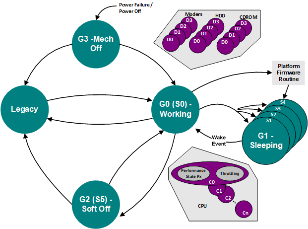
Fig. 3.1 Global System Power States and Transitions
See Section 2.2 for detailed definitions of these states.
In general use, computers alternate between the Working and Sleeping states. In the Working state, the computer is used to do work. User-mode application threads are dispatched and running. Individual devices can be in low-power (Dx) states and processors can be in low-power (Cx) states if they are not being used. Any device the system turns off because it is not actively in use can be turned on with short latency. (What “short” means depends on the device. An LCD display needs to come on in sub-second times, while it is generally acceptable to wait a few seconds for a printer to wake.)
The net effect of this is that the entire machine is functional in the Working state. Various Working sub-states differ in speed of computation, power used, heat produced, and noise produced. Tuning within the Working state is largely about trade-offs among speed, power, heat, and noise.
When the computer is idle or the user has pressed the power button, the OS will put the computer into one of the sleeping (Sx) states. No user-visible computation occurs in a sleeping state. The sleeping sub-states differ in what events can arouse the system to a Working state, and how long this takes. When the machine must awaken to all possible events or do so very quickly, it can enter only the sub-states that achieve a partial reduction of system power consumption. However, if the only event of interest is a user pushing on a switch and a latency of minutes is allowed, the OS could save all system context into an NVS file and transition the hardware into the S4 sleeping state. In this state, the machine draws almost zero power and retains system context for an arbitrary period of time (years or decades if needed).
The other states are used less often. Computers that support legacy BIOS power management interfaces boot in the Legacy state and transition to the Working state when an ACPI OS loads. A system without legacy support (for example, a RISC system) transitions directly from the Mechanical Off state to the Working state. Users typically put computers into the Mechanical Off state by flipping the computer’s mechanical switch or by unplugging the computer.
3.2.1. Power Button
In legacy systems, the power button typically either forces the machine into Soft Off or Mechanical Off or, on a laptop, forces it to some sleeping state. No allowance is made for user policy (such as the user wants the machine to “come on” in less than 1 second with all context as it was when the user turned the machine “off”), system alert functions (such as the system being used as an answering machine or fax machine), or application function (such as saving a user file).
In an OSPM system, there are two switches. One is to transition the system to the Mechanical Off state. A mechanism to stop current flow is required for legal reasons in some jurisdictions (for example, in some European countries). The other is the “main” power button. This is in some obvious place (for example, beside the keyboard on a laptop). Unlike legacy on/off buttons, all it does is send a request to the system. What the system does with this request depends on policy issues derived from user preferences, user function requests, and application data.
3.2.2. Platform Power Management Characteristics
3.2.2.1. Mobile PC
Mobile PCs will continue to have aggressive power management functionality. Going to OSPM/ACPI will allow enhanced power savings techniques and more refined user policies.
Aspects of mobile PC power management in the ACPI specification are thermal management (see Section 3.10).
3.2.2.2. Desktop PCs
Power-managed desktops will be of two types, though the first type will migrate to the second over time.
- Ordinary “Green PC”
Here, new appliance functions are not the issue. The machine is really only used for productivity computations. At least initially, such machines can get by with very minimal function. In particular, they need the normal ACPI timers and controls, but don’t need to support elaborate sleeping states, and so on. They, however, do need to allow the OS to put as many of their devices/resources as possible into device standby and device off states, as independently as possible (to allow for maximum compute speed with minimum power wasted on unused devices). Such PCs will also need to support wake from the sleeping state by means of a timer, because this allows administrators to force them to turn on just before people are to show up for work.
- Home PC
Computers are moving into home environments where they are used in entertainment centers and to perform tasks like answering the phone. A home PC needs all of the functionality of the ordinary green PC. In fact, it has all of the ACPI power functionality of a laptop except for docking and lid events (and need not have any legacy power management). Note that there is also a thermal management aspect to a home PC, as a home PC user wants the system to run as quietly as possible, often in a thermally constrained environment.
3.2.2.3. Multiprocessor and Server PCs
Perhaps surprisingly, server machines often get the largest absolute power savings. Why? Because they have the largest hardware configurations and because it’s not practical for somebody to hit the off switch when they leave at night.
- Day Mode
In day mode, servers are power-managed much like a corporate ordinary green PC, staying in the Working state all the time, but putting unused devices into low-power states whenever possible. Because servers can be very large and have, for example, many disk spindles, power management can result in large savings. OSPM allows careful tuning of when to do this, thus making it workable.
- Night Mode
In night mode, servers look like home PCs. They sleep as deeply as they can and are still able to wake and answer service requests coming in over the network, phone links, and so on, within specified latencies. So, for example, a print server might go into deep sleep until it receives a print job at 3 A.M., at which point it wakes in perhaps less than 30 seconds, prints the job, and then goes back to sleep. If the print request comes over the LAN, then this scenario depends on an intelligent LAN adapter that can wake the system in response to an interesting received packet.
3.3. Device Power Management
This section describes ACPI-compatible device power management. The ACPI device power states are introduced, the controls and information an ACPI-compatible OS needs to perform device power management are discussed, the wake operation devices use to wake the computer from a sleeping state is described, and an example of ACPI-compatible device management using a modem is given
3.3.1. Device Power Management Model
ACPI Device Power Management is based on an integrated model consisting of:
- Distributed device power state policy
For each hardware device on the system, there is a Power Policy Owner in the Operating System that is responsible for continuously determining the best power state for the device. The best device power state is the one that, at any point in time, minimizes the consumption of power by the device consistent with the usage requirements of the device by the system and its user. Policy is typically defined for a class of devices, and incorporates application activity, user scenarios and other operating state as necessary. It is applied to all devices of a given class.
- Layered device power state control
Once power state decisions are made for a device, they must be carried-out by device drivers. The model partitions the control functionality between the device, bus and platform layers. Device drivers at each layer perform control using mechanisms available at that level, coordinated by OSPM. In general, the ordering proceeds from Device/Class level, to Bus level, to Platform level when a device is powering down, and the inverse when powering-up.
For instance, a device-level driver has access, via the device programming interface, to settings and control registers that invoke specific, sometimes proprietary, power control features in the device. The device driver uses these controls as appropriate for the target ACPI-defined power state determined by the policy owner. Similarly, classes of devices may have standardized power features, invoked in standardized ways that Class Drivers might use when entering a target power state.
At the bus level, power management standards come into play to provide bus-specific controls that work for every device connected to the bus, regardless of device class. PCI, for instance, defines fields in the device Configuration Space for setting the device’s power state (D0-D3). Bus-level drivers utilize these standards to perform control in addition to that applied by the device-specific or device class driver. Bus-specific mechanisms also enable additional power savings in the system by enabling the bus infrastructure hardware itself to enter lower power states, as defined in the bus standard.
Finally, for platform-level power state control, ACPI defines mechanisms (_PRx, _PSx, _ON, _OFF) for putting a device into a given power state. The Operating System’s Power Management software (OSPM) utilizes these mechanisms to execute the lowest-level, platform-specific control for a given device (such as turning power rails and clocks off and on, resetting hardware, etc.).
- Operating System coordination
Finally, ACPI defines information and behavior requirements that enable OSPM to inform the Power Policy Owner about supported state and wake-up capabilities, and to coordinate the actions of the various levels of device drivers in controlling power. OSPM, in this role, is responsible for ensuring that device power management is coordinated with System Power Management such as entering sleep states (S1-S4) or Low-power Idle states (LPI). Integrated with device power state policy and control, wake-up policy and control are also coordinated by OSPM. Power Policy Owners, which decide when the device might be needed to wake the system, ensure that only device power states that the device can wake from are selected when the platform enters a Sleep or LPI state. Enabling of wake-up hardware is also performed at the device, bus and platform levels and coordinated by OSPM. OSPM ensures further that the Sleep or LPI state selected for the system is compatible with the device state and wake-up capabilities of all the devices currently enabled for wake.
3.3.2. Power Management Standards
To manage power of all the devices in the system, the OS needs standard methods for sending commands to a device. These standards define the operations used to manage power of devices on a particular I/O interconnect and the power states that devices can be put into. Defining these standards for each I/O interconnect creates a baseline level of power management support the OS can utilize. Independent Hardware Vendors (IHVs) do not have to spend extra time writing software to manage power of their hardware, because simply adhering to the standard gains them direct OS support. For OS vendors, the I/O interconnect standards allow the power management code to be centralized in the driver for each I/O interconnect. Finally, I/O interconnect-driven power management allows the OS to track the states of all devices on a given I/O interconnect. When all the devices are in a given state (or example, D3 - off), the OS can put the entire I/O interconnect into the power supply mode appropriate for that state (for example, D3 - off).
I/O interconnect-level power management specifications are written for a number of buses including:
PCI
PCI Express
CardBus
USB
IEEE 1394
3.3.3. Device Power States
To unify nomenclature and provide consistent behavior across devices, standard definitions are used for the power states of devices. Generally, these states are defined in terms of the following criteria:
Power consumption–How much power the device uses.
Device context–How much of the context of the device is retained by the hardware.
Device driver–What the device driver must do to restore the device to fully on.
Restore latency–How long it takes to restore the device to fully on.
More specifically, power management specifications for each class of device (for example, modem, network adapter, hard disk, and so on) more precisely define the power states and power policy for the class. See Device Power States for a detailed description of the general device power states (D0-D3).
3.3.4. Device Power State Definitions
The device power state definitions are device-independent, but classes of devices on a bus must support some consistent set of power-related characteristics. For example, when the bus-specific mechanism to set the device power state to a given level is invoked, the actions a device might take and the specific sorts of behaviors the OS can assume while the device is in that state will vary from device type to device type. For a fully integrated device power management system, these class-specific power characteristics must also be standardized:
- Device Power State Characteristics
Each class of device has a standard definition of target power consumption levels, state-change latencies, and context loss.
- Minimum Device Power Capabilities
Each class of device has a minimum standard set of power capabilities.
- Device Functional Characteristics
Each class of device has a standard definition of what subset of device functionality or features is available in each power state (for example, the net card can receive, but cannot transmit; the sound card is fully functional except that the power amps are off, and so on).
- Device Wakeup Characteristics
Each class of device has a standard definition of its wake policy.
The Device Class power management specifications define these power state characteristics for each class of device. See Appendix A: Device Class Specifications.
3.4. Controlling Device Power
ACPI interfaces provide the control methods and information needed to manage device power. OSPM leverages these interfaces to perform tasks like determining the capabilities of a device, executing methods to set a device’s power state or get its status, and enabling a device to wake the machine.
Other buses enumerate some devices on the main board. For example, PCI devices are reported through the standard PCI enumeration mechanisms. Power management of these devices is handled through their own bus specification (in this case, PCI). All other devices on the main board are handled through ACPI. Specifically, the ACPI table lists legacy devices that cannot be reported through their own bus specification, the root of each bus in the system, and devices that have additional power management or configuration options not covered by their own bus specification.
For more detailed information see Section 7
3.4.1. Getting Device Power Capabilities
As the OS enumerates devices in the system, it gets information about the power management features that the device supports. The Differentiated Definition Block given to the OS by the platform boot firmware describes every device handled by ACPI. This description contains the following information:
A description of what power resources (power planes and clock sources) the device needs in each power state that the device supports. For example, a device might need a high power bus and a clock in the D0 state but only a low-power bus and no clock in the D2 state.
A description of what power resources a device needs in order to wake the machine (or none to indicate that the device does not support wake). The OS can use this information to infer what device and system power states from which the device can support wake.
The optional control method the OS can use to set the power state of the device and to get and set resources.
In addition to describing the devices handled by ACPI, the table lists the power planes and clock sources themselves and the control methods for turning them on and off. For detailed information, see Section 7.
3.4.2. Setting Device Power States
OSPM uses the Set Power State operation to put a device into one of the four power states.
When a device is put in a lower power state, it configures itself to draw as little power from the bus as possible. The OS tracks the state of all devices on the bus, and will put the bus in the best power state based on the current device requirements on that bus. For example, if all devices on a bus are in the D3 state, the OS will send a command to the bus control chip set to remove power from the bus (thus putting the bus in the D3 state). If a particular bus supports a low-power supply state, the OS puts the bus in that state if all devices are in the D1 or D2 state. Whatever power state a device is in, the OS must be able to issue a Set Power State command to resume the device.
The device does not need to have power to do this. The OS must turn on power to the device before it can send commands to the device.
OSPM also uses the Set Power State operation to enable power management features such as wake (described in Power and Performance Management).
For power-down operations (transitions from Dx to some deeper Dy), OSPM first evaluates the appropriate control method for the target state (_PSx), then turns-off any unused power resources. Notice that this might not mean that power is actually removed from the device. If other active devices are sharing a power resource, the power resource will remain on. In the power-up case (transitions from some Dx back to the shallower D0), the power resources required for D0 are first turned on, and then the control method (_PS0) is evaluated.
3.4.3. Getting Device Power Status
OSPM uses the Get Power Status operation to determine the current power configuration (states and features), as well as the status of any batteries supported by the device. The device can signal an SCI to inform the OS of changes in power status. For example, a device can trigger an interrupt to inform the OS that the battery has reached low power level.
Devices use the ACPI event model to signal power status changes (for example, battery status changes) to OSPM. The platform signals events to the OS via an interrupt, either SCI, or GPIO. An interrupt status bit is set to indicate the event to the OS. The OS runs the control method associated with the event. This control method signals to the OS which device has changed.
ACPI supports two types of batteries: batteries that report only basic battery status information and batteries that support the Smart Battery System Implementers Forum “Smart Battery Specification”. For batteries that report only basic battery status information (such as total capacity and remaining capacity), the OS uses control methods from the battery’s description table to read this information. To read status information for Smart Batteries, the OS can use a standard Smart Battery driver that directly interfaces to Smart Batteries through the appropriate bus enumerator.
3.4.4. Waking the System
The wake operation enables devices to wake the system from a sleeping or low-power idle state. This operation must not depend on the CPU because the CPU will not be executing instructions.
The OS ensures any bridges between the device and the core logic are in the lowest power state in which they can still forward the wake signal. When a device with wake enabled decides to wake the system, it sends the defined signal on its bus. Bus bridges must forward this signal to upstream bridges using the appropriate signal for that bus. Thus, the signal eventually reaches the core chip set (for example, an ACPI chip set), which in turn wakes the system.
Before putting the system in a sleeping power state, the OS determines which devices are needed to wake the system based on application requests, and then enables wake on those devices in a device and bus specific manner.
The OS enables the wake feature on devices by setting that device’s SCI Enable bit or unmasking its wake interrupt. The location of this control is listed in the device’s entry in the description table. Only devices that have their wake feature enabled can wake the system. The OS keeps track of the power states that the wake devices support, and keeps the system in a power state in which the wake can still wake the system (based on capabilities reported in the description table).
When the system is in a Sleeping or low-power idle state and a wake device decides to wake the system, it signals to the core logic. The status bit corresponding to the device waking the system is set, and the core logic resumes the system. After the OS is running again, it determines the device responsible for the wake event by either running a control method (for wake events) or processing the device’s ISR (for wake interrupts).
Besides using ACPI mechanism to enable a particular device to wake the system, an ACPI platform must also be able to record and report the wake source to OSPM. When a system is woken from certain states (such as the S4 state), it may start out in non-ACPI mode. In this case, the SCI status bit may be cleared when ACPI mode is re-entered. However the platform must still attempt to record the wake source for retrieval by OSPM at a later point.
Although the above description explains how a device can wake the system, note that a device can also be put into a low power state during the S0 system state, and that this device may generate a wake signal in the S0 state as the following example illustrates.
3.4.5. Example: Modem Device Power Management
To illustrate how these power management methods function in ACPI, consider an integrated modem. (This example is greatly simplified for the purposes of this discussion.) The power states of a modem are defined as follows (from the Modem Device Class Power Management Specification):
- D0
Modem controller on Phone interface on Speaker on Can be on hook or off hook Can be waiting for answer
- D1
Modem controller in low-power mode (context retained by device) Phone interface powered by phone line or in low-power mode Speaker off Must be on hook
- D2
Same as D3
- D3
Modem controller off (context lost) Phone interface powered by phone line or off Speaker off On hook
The power policy for the modem is defined as follows:
- D3 D0
COM port opened
- D0, D1 D3
COM port closed
- D0 D1
Modem put in answer mode
- D1 D0
Application requests dial or the phone rings while the modem is in answer mode
The wake policy for the modem is very simple: When the phone rings and wake is enabled, wake the system.
Based on that policy, the modem and the COM port to which it is attached can be implemented in hardware as shown in Figure 3-2. This is just an example for illustrating features of ACPI. This example is not intended to describe how OEMs should build hardware.
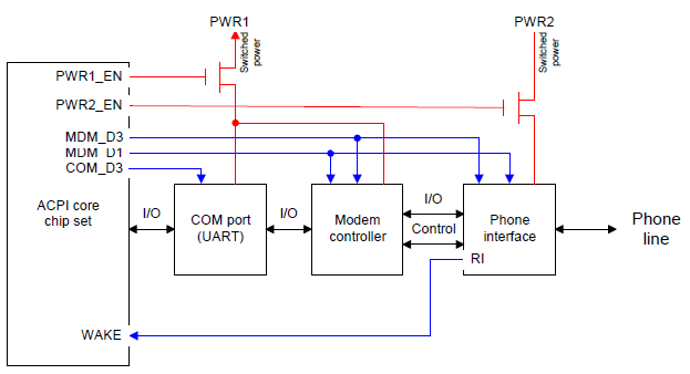
Fig. 3.2 Example Modem and COM Port Hardware
Note
Although not shown above, each discrete part has some isolation logic so that the part is isolated when power is removed from it. Isolation logic controls are implemented as power resources in the ACPI Differentiated Description Block so that devices are isolated as power planes are sequenced off.
3.4.5.1. Obtaining the Modem Capabilities
The OS determines the capabilities of this modem when it enumerates the modem by reading the modem’s entry in the Differentiated Definition Block. In this case, the entry for the modem would report:
The device supports D0, D1, and D3:
D0 requires PWR1 and PWR2 as power resources D1 requires PWR1 as a power resource (D3 implicitly requires no power resources)
To wake the system, the modem needs no power resources (implying it can wake the system from D0, D1, and D3)
Control methods for setting power state and resources
3.4.5.2. Setting the Modem Power State
While the OS is running (G0 state), it switches the modem to different power states according to the power policy defined for modems.
When an application opens the COM port, the OS turns on the modem by putting it in the D0 state. Then if the application puts the modem in answer mode, the OS puts the modem in the D1 state to wait for the call. To make this power-down transition, OSPM first runs a control method (_PS1) provided in the modem’s entry to put the device in the D1 state. In this example, this control method asserts the MDM_D1 signal that tells the modem controller to go into a low-power mode. OSPM then checks to see what power resources are no longer needed by the modem device. In this case, PWR2 is no longer needed. Then it checks to make sure no other device in the system requires the use of the PWR2 power resource. If the resource is no longer needed, the OSPM uses the _OFF control method associated with that power resource in the Differentiated Definition Block to turn off the PWR2 power plane. This control method sends the appropriate commands to the core chip set to stop asserting the PWR2_EN line.
OSPM does not always turn off power resources when a given device is put in a lower power state. For example, assume that the PWR1 power plane also powers an active line printer (LPT) port. Suppose the user terminates the modem application, causing the COM port to be closed, and therefore causing the modem to be shut off (state D3). As always, OSPM begins the state transition process by running the modem’s control method to switch the device to the D3 power state. The control method causes the MDM_D3 line to be asserted. Notice that these registers might not be in the device itself. For example, the control method could read the register that controls MDM_D3.The modem controller now turns off all its major functions so that it draws little power, if any, from the PWR1 line. OSPM continues by checking to see which power resources are no longer needed. Because the LPT port is still active, PWR1 is in use. OSPM does not turn off the PWR1 resource. Because the COM port is closed, the same sequence of events take place to put it in the D3 state, but the power resource is not turned off due to the LPT dependency.
3.4.5.3. Obtaining the Modem Power Status
Integrated modems have no batteries; the only power status information for the device is the power state of the modem. To determine the modem’s current power state (D0-D3), OSPM runs a control method (_PSC) supplied in the modem’s entry in the Differentiated Definition Block. This control method reads from the necessary registers to determine the modem’s power state.
3.4.5.4. Waking the System
As indicated in the modem capabilities, this modem can wake the machine from any device power state. Before putting the system in a Sleep or LPI state, the OS enables wake on any devices that applications have requested to be able to wake the system. Then, it chooses the deepest sleeping or LPI state that can still provide the power resources necessary to allow all enabled wake devices to wake the system. Next, the OS puts each of those devices in the appropriate power state. In this case, the OS puts the modem in the D3 state because it supports wake from that state. Finally, the OS puts the system into a sleep or LPI state.
Waking the system via modem starts with the modem’s phone interface asserting its ring indicate (RI) line when it detects a ring on the phone line. This line is routed to the core logic to generate a wake event. The chipset then wakes the system and the hardware will eventually pass control back to the OS (the wake mechanism differs depending on the sleeping state, or LPI). After the OS is running, it puts the device in the D0 state and begins handling interrupts from the modem to process the event.
3.5. Processor Power Management
To further save power in the Working state, the OS puts the CPU into low-power states (C1, C2, and C3) when the OS is idle. In these low-power states, the CPU does not run any instructions, and wakes when an interrupt, such as the OS scheduler’s timer interrupt, occurs.
The OS determines how much time is being spent in its idle loop by reading the ACPI Power Management Timer. This timer runs at a known, fixed frequency and allows the OS to precisely determine idle time. Depending on this idle time estimate, the OS will put the CPU into different quality low-power states (which vary in power and latency) when it enters its idle loop.
The CPU states are defined in detail in Processor Configuration and Control
3.6. Device and Processor Performance States
This section describes the concept of device and processor performance states. Device and processor performance states (Px states) are power consumption and capability states within the active/executing states, C0 for processors and D0 for devices. Performance states allow OSPM to make tradeoffs between performance and energy conservation. Device and processor performance states have the greatest impact when the states invoke different device and processor efficiency levels as opposed to a linear scaling of performance and energy consumption. Since performance state transitions occur in the active/executing device states, care must be taken to ensure that performance state transitions do not adversely impact the system.
Examples of device performance states include:
A hard drive that provides levels of maximum throughput that correspond to levels of power consumption.
An LCD panel that supports multiple brightness levels that correspond to levels of power consumption.
A graphics component that scales performance between 2D and 3D drawing modes that corresponds to levels of power consumption.
An audio subsystem that provides multiple levels of maximum volume that correspond to levels of maximum power consumption.
A Direct-RDRAMTM controller that provides multiple levels of memory throughput performance, corresponding to multiple levels of power consumption, by adjusting the maximum bandwidth throttles.
Processor performance states are described in Processor Configuration and Control
3.7. Configuration and “Plug and Play”
In addition to power management, ACPI interfaces provide controls and information that enable OSPM to configure the required resources of motherboard devices along with their dynamic insertion and removal. ACPI Definition Blocks, including the Differentiated System Description Table (DSDT) and Secondary System Description Tables (SSDTs), describe motherboard devices in a hierarchical format called the ACPI namespace. The OS enumerates motherboard devices simply by reading through the ACPI Namespace looking for devices with hardware IDs.
Each device enumerated by ACPI includes ACPI-defined objects in the ACPI Namespace that report the hardware resources that the device could occupy, an object that reports the resources that are currently used by the device, and objects for configuring those resources. The information is used by the Plug and Play OS (OSPM) to configure the devices.
Note
When preparing to boot a system, the platform boot firmware only needs to configure boot devices. This includes boot devices described in the ACPI system description tables as well as devices that are controlled through other standards.
3.7.1. Device Configuration Example: Configuring the Modem
Returning to the modem device example above, the OS will find the modem and load a driver for it when the OS finds it in the DSDT. This table will have control methods that give the OS the following information:
The device can use IRQ 3, I/O 3F8-3FF or IRQ 4, I/O 2E8-2EF
The device is currently using IRQ 3, I/O 3F8-3FF
The OS configures the modem’s hardware resources using Plug and Play algorithms. It chooses one of the supported configurations that does not conflict with any other devices. Then, OSPM configures the device for those resources by running a control method supplied in the modem’s section of the Differentiated Definition Block. This control method will write to any I/O ports or memory addresses necessary to configure the device to the given resources.
3.7.2. NUMA Nodes
Systems employing a Non Uniform Memory Access (NUMA) architecture contain collections of hardware resources including processors, memory, and I/O buses, that comprise what is commonly known as a “NUMA node”. Processor accesses to memory or I/O resources within the local NUMA node is generally faster than processor accesses to memory or I/O resources outside of the local NUMA node. ACPI defines interfaces that allow the platform to convey NUMA node topology information to OSPM both statically at boot time and dynamically at run time as resources are added or removed from the system.
3.8. System Events
ACPI includes a general event model used for Plug and Play, Thermal, and Power Management events. There are two registers that make up the event model: an event status register and an event enable register.
When an event occurs, the core logic sets a bit in the status register to indicate the event. If the corresponding bit in the enable register is set, the core logic will assert the SCI to signal the OS. When the OS receives this interrupt, it will run the control methods corresponding to any bits set in the event status register. These control methods use AML commands to tell the OS what event occurred.
For example, assume a machine has all of its Plug and Play, Thermal, and Power Management events connected to the same pin in the core logic. The event status and event enable registers would only have one bit each: the bit corresponding to the event pin.
When the system is docked, the core logic sets the status bit and signals the SCI. The OS, seeing the status bit set, runs the control method for that bit. The control method checks the hardware and determines the event was a docking event (for example). It then signals to the OS that a docking event has occurred, and can tell the OS specifically where in the device hierarchy the new devices will appear.
Since the event model registers are generalized, they can describe many different platform implementations. The single pin model above is just one example. Another design might have Plug and Play, Thermal, and Power Management events wired to three different pins so there would be three status bits (and three enable bits). Yet another design might have every individual event wired to its own pin and status bit. This design, at the opposite extreme from the single pin design, allows very complex hardware, yet very simple control methods. Countless variations in wiring up events are possible. However, note that care must be taken to ensure that if events share a signal that the event that generated the signal can be determined in the corresponding event handling control method allowing the proper device notification to be sent.
3.9. Battery Management
Battery management policy moves from the APM BIOS to the ACPI-compatible OS. Batteries must comply with the requirements of their associated interfaces, as described either herein or in other applicable standards. The OS may choose to alter the behavior of the battery, for example, by adjusting the Low Battery or Battery Warning trip point. When there are multiple batteries present, the battery subsystem is not required to perform any synthesis of a “composite battery” from the data of the separate batteries. In cases where the battery subsystem does not synthesize a “composite battery” from the separate battery’s data, the OS must provide that synthesis.
An ACPI-compatible battery device needs either a Smart Battery subsystem interface or a Control Method Battery interface.
Smart Battery is controlled by the OS directly through the embedded controller (EC). See Section 10.1 and Section 12.9 for more information.
Control Method Battery is completely accessed by AML code control methods, allowing the OEM to choose any type of battery and any kind of communication interface supported by ACPI. See Section 10.2 for more information.
This section describes concepts common to all battery types.
3.9.1. Battery Communications
Both the Smart Battery and Control Method Battery interfaces provide a mechanism for the OS to query information from the platform’s battery system. This information may include full charged capacity, present battery capacity, rate of discharge, and other measures of the battery’s condition. All battery system types must provide notification to the OS when there is a change such as inserting or removing a battery, or when a battery starts or stops discharging. Smart Batteries and some Control Method Batteries are also able to give notifications based on changes in capacity. Smart batteries provide extra information such as estimated run-time, information about how much power the battery is able to provide, and what the run-time would be at a predetermined rate of consumption.
3.9.2. Battery Capacity
Each battery must report its designed capacity, latest full-charged capacity, and present remaining capacity. Remaining capacity decreases during usage, and it also changes depending on the environment. Therefore, the OS must use latest full-charged capacity to calculate the battery percentage. In addition the battery system must report warning and low battery levels at which the user must be notified and the system transitioned to a sleeping state. See Fig. 3.3 for the relation of these five values.
A system may use either rate and capacity [mA/mAh] or power and energy [mW/mWh] for the unit of battery information calculation and reporting. Mixing [mA] and [mW] is not allowed on a system.
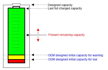
Fig. 3.3 Reporting Battery Capacity
3.9.3. Battery Gas Gauge
At the most basic level, the OS calculates Remaining Battery Percentage [%] using the following formula:

Fig. 3.4 Formula for Remaining Battery Percentage
Control Method Battery also reports the Present Drain Rate [mA or mW] for calculating the remaining battery life. At the most basic level, Remaining Battery life is calculated by following formula:

Fig. 3.5 Formula for the Present Drain Rate
Smart Batteries also report the present rate of drain, but since they can directly report the estimated run-time, this function should be used instead as it can more accurately account for variations specific to the battery.
3.9.4. Low Battery Levels
A system has an OEM-designed initial capacity for warning, initial capacity for low, and a critical battery level or flag. The values for warning and low represent the amount of energy or battery capacity needed by the system to take certain actions. The critical battery level or flag is used to indicate when the batteries in the system are completely drained. OSPM can determine independent warning and low battery capacity values based on the OEM-designed levels, but cannot set these values lower than the OEM-designed values, as shown in the figure below.
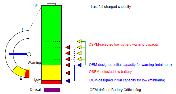
Fig. 3.6 Low Battery and Warning
Each Control Method Battery in a system reports the OEM-designed initial warning capacity and OEM-designed initial low capacity as well as a flag to report when that battery has reached or is below its critical energy level. Unlike Control Method Batteries, Smart Batteries are not necessarily specific to one particular machine type, so the OEM-designed warning, low, and critical levels are reported separately in a Smart Battery Table described in Smart Battery Table (SBST) .
The table below describes how these values should be set by the OEM and interpreted by the OS.
Level |
Description |
|---|---|
Warning |
When the total available energy (mWh) or capacity (mAh) in the batteries falls below this level, the OS will notify the user through the UI. This value should allow for a few minutes of run-time before the “Low” level is encountered so the user has time to wrap up any important work, change the battery, or find a power outlet to plug the system in. |
Low |
This value is an estimation of the amount of energy or battery capacity required by the system to transition to any supported sleeping state. When the OS detects that the total available battery capacity is less than this value, it will transition the system to a user defined system state (S1-S4). In most situations this should be S4 so that system state is not lost if the battery eventually becomes completely empty. The design of the OS should consider that users of a multiple battery system may remove one or more of the batteries in an attempt replace or charge it. This might result in the remaining capacity falling below the “Low” level not leaving sufficient battery capacity for the OS to safely transition the system into the sleeping state. Therefore, if the batteries are discharging simultaneously, the action might need to be initiated at the point when both batteries reach this level. |
Critical |
The Critical battery state indicates that all available batteries are discharged and do not appear to be able to supply power to run the system any longer. When this occurs, the OS must attempt to perform an emergency shutdown as described below. For a smart battery system, this would typically occur when all batteries reach a capacity of 0, but an OEM may choose to put a larger value in the Smart Battery Table to provide an extra margin of safely. For a Control Method Battery system with multiple batteries, the flag is reported per battery. If any battery in the system is in a critically low state and is still providing power to the system (in other words, the battery is discharging), the system is considered to be in a critical energy state. The _BST control method is required to return the Critical flag on a discharging battery only when all batteries have reached a critical state; the ACPI system firmware is otherwise required to switch to a non-critical battery. |
3.9.4.1. Emergency Shutdown
Running until all batteries in a system are critical is not a situation that should be encountered normally, since the system should be put into a sleeping state when the battery becomes low. In the case that this does occur, the OS should take steps to minimize any damage to system integrity. The emergency shutdown procedure should be designed to minimize bad effects based on the assumption that power may be lost at any time. For example, if a hard disk is spun down, the OS should not try to spin it up to write any data, since spinning up the disk and attempting to write data could potentially corrupt files if the write were not completed. Even if a disk is spun up, the decision to attempt to save even system settings data before shutting down would have to be evaluated since reverting to previous settings might be less harmful than having the potential to corrupt the settings if power was lost halfway through the write operation.
3.9.5. Battery Calibration
The reported capacity of many batteries generally degrade over time, providing less run time for the user. However, it is possible with many battery systems to provide more usable runtime on an old battery if a calibration or conditioning cycle is run occasionally. The user has typically been able to perform a calibration cycle either by going into the platform boot firmware setup menu, or by running a custom driver and calibration application provided by the OEM. The calibration process typically takes several hours, and the laptop must be plugged in during this time. Ideally the application that controls this should make this as good of a user experience as possible, for example allowing the user to schedule the system to wake up and perform the calibration at some time when the system will not be in use. Since the calibration user experience does not need to be different from system to system it makes sense for this service to be provided by the OSPM. In this way OSPM can provide a common experience for end users and eliminate the need for OEMs to develop custom battery calibration software.
In order for OSPM to perform generic battery calibration, generic interfaces to control the two basic calibration functions are required. These functions are defined in Power Source and Power Meter Devices and _BST (Battery Status). First, there is a means to detect when it would be beneficial to calibrate the battery. Second there is a means to perform that calibration cycle. Both of those functions may be implemented by dedicated hardware such as a battery controller chip, by firmware in the embedded controller, by the platform firmware, or by OSPM. From here on any function implemented through AML, whether or not the AML code relies on hardware, will be referred to as “AML controlled” since the interface is the same whether the AML passes control to the hardware or not.
Detection of when calibration is necessary can be implemented by hardware or AML code and be reported through the _BMD method. Alternately, the _BMD method may simply report the number of cycles before calibration should be performed and let the OS attempt to count the cycles. A counter implemented by the hardware or the platform firmware will generally be more accurate since the batteries can be used without the OS running, but in some cases, a system designer may opt to simplify the hardware or firmware implementation.
When calibration is desirable and the user has scheduled the calibration to occur, the calibration cycle can be AML controlled or OSPM controlled. OSPM can only implement a very simple algorithm since it doesn’t have knowledge of the specifics of the battery system. It will simply discharge the battery until it quits discharging, then charge it until it quits charging. In the case where the AC adapter cannot be controlled through the _BMC, it will prompt the user to unplug the AC adapter and reattach it after the system powers off. If the calibration cycle is controlled by AML, the OS will initiate the calibration cycle by calling _BMC. That method will either give control to the hardware, or will control the calibration cycle itself. If the control of the calibration cycle is implemented entirely in AML code, the platform runtime firmware may avoid continuously running AML code by having the initial call to _BMC start the cycle, set some state flags, and then exit. Control of later parts of the cycle can be accomplished by putting code that checks these state flags in the battery event handler (_Qxx, _Lxx, or _Exx).
Details of the control methods for this interface are defined in Control Method Batteries.
3.9.6. Battery Charge Limiting
If the Platform is said to support Battery Charge Limiting feature, it must:
Advertise true charge level to the OSPM, at all times for all installed batteries
Limit the battery from reaching its Full Charge Capacity when Battery Charge Limiting is active
Set _BST.Battery State.Bit[3] when Battery Charge Limiting is active
Ensure that _BST.Battery State (Bit 0 and Bit 1) reflect true charging/discharging state of the battery
OSPM must recognize the following settings:
_BST.Battery State.Bit[3] |
_BST.Battery State.Bit[0] |
_BST.Battery State.Bit[1] |
Interpretation |
|---|---|---|---|
Cleared |
N/A |
N/A |
Battery Charge Limiting is disengaged |
Set |
Cleared |
Cleared |
Battery Charge Limiting is engaged, and the battery has reached the steady state, it will not be charged or discharged |
Set |
Cleared |
Set |
Battery Charge Limiting is engaged, and the battery has not reached the steady state |
Set |
Set |
Cleared |
Battery Charge Limiting is engaged, and the battery has not reached the steady state |
3.10. Thermal Management Concepts
ACPI allows the OS to play a role in the thermal management of the system while maintaining the platform’s ability to mandate cooling actions as necessary. In the passive cooling mode, OSPM can make cooling decisions based on application load on the CPU as well as the thermal heuristics of the system. OSPM can also gracefully shutdown the computer in case of high temperature emergencies.
The ACPI thermal design is based around regions called thermal zones. Generally, the entire PC is one large thermal zone, but an OEM can partition the system into several logical thermal zones if necessary. Thermal Zone is an example mobile PC diagram that depicts a single thermal zone with a central processor as the thermal-coupled device. In this example, the whole notebook is covered as one large thermal zone. This notebook uses one fan for active cooling and the CPU for passive cooling.
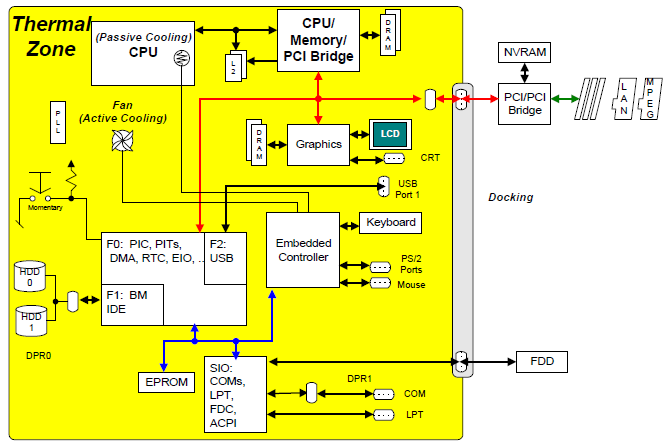
Fig. 3.7 Thermal Zone
The following sections are an overview of the thermal control and cooling characteristics of a computer. For some thermal implementation examples on an ACPI platform, see Section 11.6
3.10.1. Active and Passive Cooling Modes
ACPI defines two cooling modes, Active and Passive:
- Passive cooling
OS reduces the power consumption of devices at the cost of system performance to reduce the temperature of the system.
- Active cooling
OS increases the power consumption of the system (for example, by turning on a fan) to reduce the temperature of the system.
These two cooling modes are inversely related to each other. Active cooling requires increased power to reduce the heat within the system while Passive cooling requires reduced power to decrease the temperature. The effect of this relationship is that Active cooling allows maximum system performance, but it may create undesirable fan noise, while Passive cooling reduces system performance, but is inherently quiet.
3.10.2. Performance vs. Energy Conservation
A robust OSPM implementation provides the means for the end user to convey to OSPM a preference (or a level of preference) for either performance or energy conservation. Allowing the end user to choose this preference is most critical to mobile system users where maximizing system run-time on a battery charge often has higher priority over realizing maximum system performance.
A user’s preference for performance corresponds to the Active cooling mode while a user’s preference for energy conservation corresponds to the Passive cooling mode. ACPI defines an interface to convey the cooling mode to the platform. Active cooling can be performed with minimal OSPM thermal policy intervention. For example, the platform indicates through thermal zone parameters that crossing a thermal trip point requires a fan to be turned on. Passive cooling requires OSPM thermal policy to manipulate device interfaces that reduce performance to reduce thermal zone temperature.
3.10.3. Acoustics (Noise)
Active cooling mode generally implies that fans will be used to cool the system and fans vary in their audible output. Fan noise can be quite undesirable given the loudness of the fan and the ambient noise environment. In this case, the end user’s physical requirement for fan silence may override the preference for either performance or energy conservation.
A user’s desire for fan silence corresponds to the Passive cooling mode. Accordingly, a user’s desire for fan silence also means a preference for energy conservation.
For more information on thermal management and examples of platform settings for active and passive cooling, see Section 3.10
3.10.4. Multiple Thermal Zones
The basic thermal management model defines one thermal zone, but in order to provide extended thermal control in a complex system, ACPI specifies a multiple thermal zone implementation. Under a multiple thermal zone model, OSPM will independently manage several thermal-coupled devices and a designated thermal zone for each thermal-coupled device, using Active and/or Passive cooling methods available to each thermal zone. Each thermal zone can have more than one Passive and Active cooling device. Furthermore, each zone might have unique or shared cooling resources. In a multiple thermal zone configuration, if one zone reaches a critical state then OSPM must shut down the entire system.
3.11. Flexible Platform Architecture Support
ACPI defines mechanisms and models to accommodate platform architectures that deviate from the traditional PC. ACPI provides support for platform technologies that enable lower-power, lower cost, more design flexibility and more device diversity. This support is described in the following sections, and detailed in later chapters.
3.11.1. Hardware-reduced ACPI
ACPI offers an alternative platform interface model that removes ACPI hardware requirements for platforms that do not implement the PC Architecture. In the Hardware-reduced ACPI model, the Fixed hardware interface requirements of Chapter 4 are removed, and Generic hardware interfaces are used instead. This provides the level of flexibility needed to innovate and differentiate in low-power hardware designs while enabling support by multiple Operating Systems.
Hardware-reduced ACPI has the following requirements:
UEFI firmware interface for boot (Legacy BIOS is not supported).
Boot in ACPI mode only (ACPI Enable, ACPI Disable, SMI_CMD and Legacy mode are not supported)
No hardware resource sharing between OSPM and other asynchronous operating environments, such as UEFI Runtime Services or System Management Mode. (The Global Lock is not supported)
No dependence on OS-support for maintaining cache coherency across processor sleep states (Bus Master Reload and Arbiter Disable are not supported)
GPE block devices are not supported
Systems that do not meet the above requirements must implement the ACPI Fixed Hardware interface.
3.11.1.1. Interrupt-based Wake Events
On HW-reduced ACPI platforms, wakeup is an attribute of connected interrupts. Interrupts that are designed to wake the processor or the entire platform are defined as wake-capable. Wake-capable interrupts, when enabled by OSPM, wake the system when they assert.
3.11.2. Low-Power Idle
Platform architectures may support hardware power management models other than the traditional ACPI Sleep/Resume model. These are typically implemented in proprietary hardware and are capable of delivering low-latency, connected idle while saving as much energy as ACPI Sleep states. To support the diversity of hardware implementations, ACPI provides a mechanism for the platform to indicate to OSPM that such capability is available.
3.11.2.1. Low Power S0 Idle Capable Flag
This flag in the FADT informs OSPM whether a platform has advanced idle power capabilities such that S0 idle achieves savings similar to or better than those typically achieved in S3. With this flag, OSPM can keep the system in S0 idle for its low-latency response and its connectedness rather than transitioning to a system sleep state which has neither. The flag enables support for a diversity of platform implementations: traditional Sleep/Resume systems, systems with advanced idle power, systems that support neither, and systems that can support both, depending on the capabilities of the installed OS.
3.11.3. Connection Resources
General-purpose I/O (GPIO) and Simple Peripheral Bus (SPB) controllers are hardware resources provided in silicon solutions to enable flexible configuration of a broad range of system designs. These controllers can provide input, output, interrupt and serial communication connections to arbitrary devices in a system. The function to which one of these connections is put depends on the specific device involved and the needs of the platform design. In order to support these platform technologies, ACPI defines a general abstraction for flexible connections.
In order to maintain compatibility with existing software models, ACPI abstracts these connections as hardware resources.
The Connection Resource abstraction mirrors the hardware functionality of GPIO and SPB controllers. Like other resources, these connections are allocated and configured before use. With the resources described by the platform, OSPM abstracts the underlying configuration from device drivers. Drivers, then, can be written for the device’s function only, and reused with that functional hardware regardless of how it is integrated into a given system.
The key aspects of the Connection Resource abstraction are:
GPIO and SPB controllers are enumerated as devices in the ACPI Namespace.
GPIO Connection and SPB Connection resource types are defined.
Namespace devices that are connected to GPIO or SPB controllers use Resource Template Macros to add Connection Resources to their resource methods (_CRS, _SRS, etc.).
GPIO Connection Resources can be designated by the platform for use as GPIO-signaled ACPI Events.
Connection Resources can be used by AML methods to access pins and peripherals through GPIO and SPB operation regions.
3.11.3.1. Supported Platforms
The HW-reduced ACPI and Low power S0 Idle Capable flags combine to represent 4 platform types that can be implemented. The following table enumerates these, as well as the intended OSPM behavior and specific platform requirements.
Low Power S0 Idle Capable |
Hardware-reduced ACPI |
OSPM Behavior |
Platform Implementation |
|---|---|---|---|
0 |
0 |
Fixed hardware interface accessed for features, events and system power management. Optionally accesses GPIO-signaled ACPI events if implemented in ACPI FW. Traditional Sleep/Resume power management. |
Implement Fixed-feature hardware interface. Optionally implements GPIO-signaled ACPI events. |
0 |
1 |
Fixed-feature hardware interface not accessed. Sleep/Resume Power Management using FADT SLEEP_*_REG fields and Interrupt-based wake signaling. |
Implement GPIO-signaled ACPI Events; Implement software alternatives to any ACPI fixed features, including the Sleep registers. Implement wake-capable interrupts for wake events. |
1 |
0 |
Fixed hardware interface accessed for features and events. Platform-specific Low-power Idle power management. Optionally accesses GPIO-signaled ACPI events if implemented in ACPI FW. |
Implement Fixed-feature hardware interface. Optionally implements GPIO-signaled ACPI events. Implement low-power hardware such that the platform achieves power savings in S0 similar to or better than those typically achieved in S3. |
1 |
1 |
Fixed-feature hardware interface not accessed. Platform-specific Low-power Idle power management. |
Implement GPIO-signaled ACPI Events; Implement software alternatives to any ACPI fixed features desired; Implement wake-capable interrupts for any wake events. Implement low-power hardware such that the platform achieves power savings in S0 similar to or better than those typically achieved in S3. |