16.1. Sleeping States
The illustration below shows the transitions between the working state, the sleeping states, and the Soft Off state.
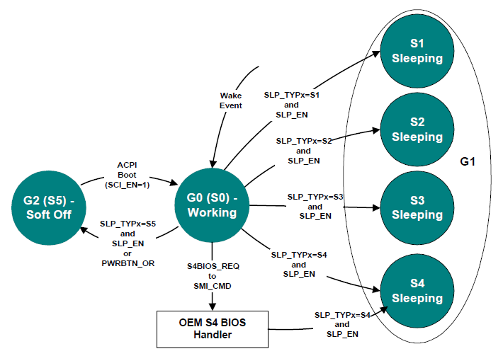
Fig. 16.1 Example Sleeping States
ACPI defines distinct differences between the G0 and G1 system states.
In the G0 state, work is being performed by the OS/application software and the hardware. The CPU or any particular hardware device could be in any one of the defined power states (C0-C3 or D0-D3); however, some work will be taking place in the system.
In the G1 state, the system is assumed to be doing no work. Prior to entering the G1 state, OSPM will place devices in a device power state compatible with the system sleeping state to be entered; if a device is enabled to wake the system, then OSPM will place these devices into the lowest Dx state from which the device supports wake. This is defined in the power resource description of that device object. This definition of the G1 state implies:
The CPUs execute no instructions in the G1 state.
Hardware devices are not operating (except possibly to generate a wake event).
If not HW-reduced, ACPI registers are affected as follows:
Wake event bits are enabled in the corresponding fixed or general-purpose registers according to enabled wake options.
PM1 control register is programmed for the desired sleeping state.
WAK_STS is set by hardware in the sleeping state.
All sleeping states have these specifications. ACPI defines additional attributes that allow an ACPI platform to have up to four different sleeping states, each of which has different attributes. The attributes were chosen to allow differentiation of sleeping states that vary in power, wake latency, and implementation cost tradeoffs.
Running processors at reduced levels of performance is not an ACPI sleeping state (G1); this is a working (G0) state-defined event.
The CPU cannot execute any instructions when in the sleeping state; OSPM relies on this fact. A platform designer might be tempted to support a sleeping system by reducing the clock frequency of the system, which allows the platform to maintain a low-power state while at the same time maintaining communication sessions that require constant interaction (as with some network environments). This is definitely a G0 activity where an OS policy decision has been made to turn off the user interface (screen) and run the processor in a reduced performance mode. This type of reduced performance state as a sleeping state is not defined by the ACPI specification; ACPI assumes no code execution during sleeping states.
ACPI defines attributes for four sleeping states: S1, S2, S3 and S4. (Notice that S4 and S5 are very similar from a hardware standpoint.) ACPI-compatible platforms can support multiple sleeping states. ACPI specifies that a 3-bit binary number be associated with each sleeping state (these numbers are given objects within ACPI’s root namespace: (\_S0, \_S1, \_S2, \_S3, \_S4 and \_S5). When entering a system sleeping state, OSPM will do the following:
Pick the deepest sleeping state supported by the platform and enabled waking devices.
Execute the _PTS control method (which passes the type of intended sleep state to OEM AML code).
If OS policy decides to enter the S4 state and chooses to use the S4BIOS mechanism and S4BIOS is supported by the platform, OSPM will pass control to the platform runtime firmware software by writing the S4BIOS_REQ value to the SMI_CMD port.
If not using the S4BIOS mechanism, OSPM gets the SLP_TYPx value from the associated sleeping object (\_S1, \_S2, \_S3, \_S4 or \_S5).
Program the SLP_TYPx fields with the values contained in the selected sleeping object.
Note
Compatibility — The _GTS method is deprecated in ACPI 5.0A. For earlier versions, execute the _GTS control method, passing an argument that indicates the sleeping state to be entered (1, 2, 3, or 4 representing S1, S2, S3, and S4).
If entering S1, S2, or S3, flush the processor caches.
If not entering S4BIOS, set the SLP_EN bit to start the sleeping sequence. (This actually occurs on the same write operation that programs the SLP_TYPx field in the PM1_CNT register.) If entering S4BIOS, write the S4BIOS_REQ value into the SMI_CMD port.
If HW-reduced, program the register indicated by the SLEEP_CONTROL_REG FADT field with the HW-reduced ACPI Sleep Type value (retrieved from the sleep state object in step 4 above) and with the SLP_EN bit set to one.
On systems containing processors without a hardware mechanism to place the processor in a low-power state, execute appropriate native instructions to place the processor in a low-power state.
The _PTS control method provides the platform runtime firmware a mechanism for performing some housekeeping, such as writing the sleep type value to the embedded controller, before entering the system sleeping state. Control method execution occurs “just prior” to entering the sleeping state and is not an event synchronized with the write to the PM1_CNT register. Execution can take place several seconds prior to the system actually entering the sleeping state. As such, no hardware power-plane sequencing takes place by execution of the _PTS control method.
Note
Compatibility — The _BFS method is deprecated in ACPI 5.0A. In earlier versions, on waking, the _BFS control method is executed. OSPM then executes the _WAK control method. This control method executes OEM-specific ASL/AML code that can search for any devices that have been added or removed during the sleeping state.*
The following sections describe the sleeping state attributes.
16.1.1. S1 Sleeping State
The S1 state is defined as a low wake-latency sleeping state. In this state, all system context is preserved with the exception of CPU caches. Before entering S1, OSPM will flush the system caches. If the platform supports the WBINVD instruction (as indicated by the WBINVD and WBINVD_FLUSH flags in the FADT), OSPM will execute the WBINVD instruction. The hardware is responsible for maintaining all other system context, which includes the context of the CPU, memory, and chipset.
Examples of S1 sleeping state implementation alternatives follow.
16.1.1.1. Example 1: S1 Sleeping State Implementation
This example references an IA processor that supports the stop grant state through the assertion of the STPCLK# signal. When SLP_TYPx is programmed to the S1 value (the OEM chooses a value, which is then placed in the \_S1 object) and the SLP_ENx bit is subsequently set, or when the HW-reduced ACPI Sleep Type value for S1 and the SLP_EN bit are written to the Sleep Control Register, the hardware can implement an S1 state by asserting the STPCLK# signal to the processor, causing it to enter the stop grant state.
In this case, the system clocks (PCI and CPU) are still running. Any enabled wake event causes the hardware to de-assert the STPCLK# signal to the processor whereby OSPM must first invalidate the CPU caches and then transition back into the working state.
16.1.1.2. Example 2: S1 Sleeping State Implementation
When SLP_TYPx is programmed to the S1 value and the SLP_ENx bit is subsequently set, or the HW-reduced ACPI Sleep Type value for S1 and the SLP_EN bit are written to the Sleep Control Register, the hardware will implement an S1 sleeping state transition by doing the following:
Placing the processor into the stop grant state.
Stopping the processor’s input clock, placing the processor into the stop clock state.
Placing system memory into a self-refresh or suspend-refresh state. Refresh is maintained by the memory itself or through some other reference clock that is not stopped during the sleeping state.
Stopping all system clocks (asserts the standby signal to the system PLL chip). Normally the RTC will continue running.
In this case, all clocks in the system have been stopped (except for the RTC). Hardware must reverse the process (restarting system clocks) upon any enabled wake event whereby OSPM must first invalidate the CPU caches and then transition back into the working state.
16.1.2. S2 Sleeping State
The S2 state is defined as a low wake latency sleep state. This state is similar to the S1 sleeping state where any context except for system memory may be lost. Additionally, control starts from the processor’s reset vector after the wake event. Before entering S2 the SLP_EN bit, OSPM will flush the system caches. If the platform supports the WBINVD instruction (as indicated by the WBINVD and WBINVD_FLUSH flags in the FADT), OSPM will execute the WBINVD instruction. The hardware is responsible for maintaining chip set and memory context. An example of an S2 sleeping state implementation follows.
16.1.2.1. Example: S2 Sleeping State Implementation
When the SLP_TYPx register(s) are programmed to the S2 value (found in the \_S2 object) and the SLP_EN bit is set, or the HW-reduced ACPI Sleep Type value for S2 and the SLP_EN bit are written to the Sleep Control Register, the hardware will implement an S2 sleeping state transition by doing the following:
Stopping system clocks (the only running clock is the RTC).
Placing system memory into a self-refresh or suspend-refresh state.
Powering off the CPU and cache subsystem.
From S2 Sleeping State the CPU is reset upon detection of the wake event; however, core logic and memory maintain their context. Execution control starts from the CPU’s boot vector. The platform boot firmware is required to:
Program the initial boot configuration of the CPU (such as the CPU’s MSR and MTRR registers).
Initialize the cache controller to its initial boot size and configuration.
Enable the memory controller to accept memory accesses.
Jump to the waking vector.
16.1.3. S3 Sleeping State
The S3 state is defined as a low wake-latency sleep state. From the software viewpoint, this state is functionally the same as the S2 state. The operational difference is that some Power Resources that may have been left ON in the S2 state may not be available to the S3 state. As such, some devices may be in a lower power state when the system is in S3 state than when the system is in the S2 state. Similarly, some device wake events can function in S2 but not S3. An example of an S3 sleeping state implementation follows.
16.1.3.1. Example: S3 Sleeping State Implementation
When the SLP_TYPx register(s) are programmed to the S3 value (found in the \_S3 object) and the SLP_EN bit is set, or the HW-reduced ACPI Sleep Type value for S3 and the SLP_EN bit are written to the Sleep Control Register, the hardware will implement an S3 sleeping state transition by doing the following:
Placing the memory into a low-power auto-refresh or self-refresh state.
Devices that are maintaining memory isolating themselves from other devices in the system.
Removing power from the system. At this point, only devices supporting memory are powered (possibly partially powered). The only clock running in the system is the RTC clock.
From S3 Sleeping State, the wake event repowers the system and resets most devices (depending on the implementation). Execution control starts from the CPU’s boot vector. The platform boot firmware is required to:
Program the initial boot configuration of the CPU (such as the MSR and MTRR registers).
Initialize the cache controller to its initial boot size and configuration.
Enable the memory controller to accept memory accesses.
Jump to the waking vector.
Notice that if the configuration of cache memory controller is lost while the system is sleeping, the platform boot firmware is required to reconfigure it to either the pre-sleeping state or the initial boot state configuration. The platform boot firmware can store the configuration of the cache memory controller into the reserved memory space, where it can then retrieve the values after waking. OSPM will call the _PTS method once per session (prior to sleeping).
The platform boot firmware is also responsible for restoring the memory controller’s configuration. If this configuration data is destroyed during the S3 sleeping state, then the platform boot firmware needs to store the pre-sleeping state or initial boot state configuration in a non-volatile memory area (as with RTC CMOS RAM) to enable it to restore the values during the waking process.
When OSPM re-enumerates buses coming out of the S3 sleeping state, it will discover any devices that have been inserted or removed, and configure devices as they are turned on.
16.1.4. S4 Sleeping State
The S4 sleeping state is the lowest-power, longest wake-latency sleeping state supported by ACPI. In order to reduce power to a minimum, it is assumed that the hardware platform has powered off all devices. Because this is a sleeping state, the platform context is maintained. Depending on how the transition into the S4 sleeping state occurs, the responsibility for maintaining system context changes. S4 supports two entry mechanisms: OS initiated and platform runtime firmware-initiated. The OSPM-initiated mechanism is similar to the entry into the S1-S3 sleeping states; OSPM driver writes the SLP_TYPx fields and sets the SLP_EN bit, or writes the HW-reduced ACPI Sleep Type value for S3 and the SLP_EN bit to the Sleep Control Register. The platform runtime firmware-initiated mechanism occurs by OSPM transferring control to the platform runtime firmware by writing the S4BIOS_REQ value to the SMI_CMD port, and is not supported on HW-reduced ACPI platforms.
In OSPM-initiated S4 sleeping state, OSPM is responsible for saving all system context. Before entering the S4 state, OSPM will save context of all memory as specified in System Address Map Interfaces.
Upon waking, OSPM shall then restore the system context. When OSPM re-enumerates buses coming out of the S4 sleeping state, it will discover any devices that have come and gone, and configure devices as they are turned on.
In the platform runtime firmware-initiated S4 sleeping state, OSPM is responsible for the same system context as described in the S3 sleeping state (platform runtime firmware restores the memory and some chip set context). The S4BIOS transition transfers control to the platform runtime firmware, allowing it to save context to non-volatile memory (such as a disk partition).
16.1.4.1. Operating System-Initiated S4 Transition
If OSPM supports OSPM-initiated S4 transition, it will not generate a platform firmware-initiated S4 transition. Platforms that support the platform firmware-initiated S4 transition also support OSPM-initiated S4 transition.
OSPM-initiated S4 transition is initiated by OSPM by saving system context, writing the appropriate values to the SLP_TYPx register(s), and setting the SLP_EN bit, or writes the HW-reduced ACPI Sleep Type value for S4 and the SLP_EN bit to the Sleep Control Register. Upon exiting the S4 sleeping state, the platform boot firmware restores the chipset to its POST condition, updates the hardware signature (described later in this section), and passes control to OSPM through a normal boot process.
When the platform boot firmware builds the ACPI tables, it generates a hardware signature for the system. If the hardware configuration has changed during an OS-initiated S4 transition, the platform boot firmware updates the hardware signature in the FACS table. A change in hardware configuration is defined to be any change in the platform hardware that would cause the platform to fail when trying to restore the S4 context; this hardware is normally limited to boot devices. For example, changing the graphics adapter or hard disk controller while in the S4 state should cause the hardware signature to change. On the other hand, removing or adding a PC Card device from a PC Card slot should not cause the hardware signature to change.
16.1.4.2. The S4BIOS Transition
This transition is not supported on HW-reduced ACPI platforms. On other systems, the platform runtime firmware-initiated S4 transition begins with OSPM writing the S4BIOS_REQ value into the SMI_CMD port (as specified in the FADT). Once gaining control, the platform runtime firmware then saves the appropriate memory and chip set context, and then places the platform into the S4 state (power off to all devices).
In the FACS memory table, there is the S4BIOS_F bit that indicates hardware support for the platform runtime firmware-initiated S4 transition. If the hardware platform supports the S4BIOS state, it sets the S4BIOS_F flag within the FACS memory structure prior to booting the OS. If the S4BIOS_F flag in the FACS table is set, this indicates that OSPM can request the platform runtime firmware to transition the platform into the S4BIOS sleeping state by writing the S4BIOS_REQ value (found in the FADT) to the SMI_CMD port (identified by the SMI_CMD value in the FADT).
Upon waking the platform boot firmware restores memory context and jumps to the waking vector (similar to wake from an S3 state). Coming out of the S4BIOS state, the platform boot firmware must only configure boot devices (so it can read the disk partition where it saved system context). When OSPM re-enumerates buses coming out of the S4BIOS state, it will discover any devices that have come and gone, and configure devices as they are turned on.
16.1.5. S5 Soft Off State
OSPM places the platform in the S5 soft off state to achieve a logical off. Notice that the S5 state is not a sleeping state (it is a G2 state) and no context is saved by OSPM or hardware but power may still be applied to parts of the platform in this state, and, as such, it is not safe to disassemble. Also notice that from a hardware perspective, the S4 and S5 states are nearly identical. When initiated, the hardware will sequence the system to a state similar to the off state. The hardware has no responsibility for maintaining any system context (memory or I/O); however, it does allow a transition to the S0 state due to a power button press or a Remote Start. Upon start-up, the platform boot firmware performs a normal power-on reset, loads the boot sector, and then executes (but not the waking vector, as all ACPI table context is lost when entering the S5 soft off state).
The _TTS control method allows the platform runtime firmware a mechanism for performing some housekeeping, such as storing the targeted sleep state in a “global” variable that is accessible by other control methods (such as _PS3 and _DSW).
16.1.6. Transitioning from the Working to the Sleeping State
On a transition of the system from the working to the sleeping state, the following occurs:
OSPM decides (through a policy scheme) to place the system into the sleeping state.
OSPM invokes the _TTS method to indicate the deepest possible system state the system will transition to (1, 2, 3, or 4 representing S1, S2, S3, and S4).
OSPM examines all devices enabled to wake the system and determines the deepest possible sleeping state the system can enter to support the enabled wake functions. The _PRW named object under each device is examined, as well as the power resource object it points to.
OSPM places all device drivers into their respective Dx state. If the device is enabled for wake, it enters the Dx state associated with the wake capability. If the device is not enabled to wake the system, it enters the D3 state.
OSPM executes the _PTS control method, passing an argument that indicates the desired sleeping state (1, 2, 3, or 4 representing S1, S2, S3, and S4).
OSPM saves any other processor’s context (other than the local processor) to memory.
OSPM writes the waking vector into the FACS table in memory.
Note
Compatibility — The _GTS method is deprecated in ACPI 5.0A. For earlier versions, OSPM executes the _GTS control method, passing an argument that indicates the sleeping state to be entered (1, 2, 3, or 4 representing S1, S2, S3, and S4).*
If not a HW-reduced ACPI platform, OSPM clears the WAK_STS in the PM1a_STS and PM1b_STS registers. On HW-reduced ACPI platforms, OSPM clears the WAK_STS bit in the Sleep Status Register.
OSPM saves the local processor’s context to memory.
OSPM flushes caches (only if entering S1, S2 or S3).
OSPM sets GPE enable registers or enables wake-capable interrupts to ensure that all appropriate wake signals are armed.
If entering an S4 state using the S4BIOS mechanism, OSPM writes the S4BIOS_REQ value (from the FADT) to the SMI_CMD port. This passes control to the platform runtime firmware, which then transitions the platform into the S4BIOS state.
If not entering an S4BIOS state, and not a HW-reduced ACPI platform, then OSPM writes SLP_TYPa (from the associated sleeping object) with the SLP_ENa bit set to the PM1a_CNT register.
OSPM writes SLP_TYPb with the SLP_EN bit set to the PM1b_CNT register, or writes the HW-reduced ACPI Sleep Type value and the SLP_EN bit to the Sleep Control Register.
On systems containing processors without a hardware mechanism to place the processor in a low-power state, OSPM executes appropriate native instructions to place the processor in a low-power state.
OSPM loops on the WAK_STS bit, either in both the PM1a_CNT and PM1b_CNT registers, or in the SLEEP_STATUS_REG, in the case of HW-reduced ACPI platforms.
The system enters the specified sleeping state.
Note
This is accomplished after step 14 or 15 above.
16.1.7. Transitioning from the Working to the Soft Off State
On a transition of the system from the working to the soft off state, the following occurs:
OSPM executes the _PTS control method, passing the argument 5.
OSPM prepares its components to shut down (flushing disk caches).
Note
Compatibility — The _GTS method is deprecated in ACPI 5.0A. For earlier versions, OSPM executes the _GTS control method, passing the argument 5.
If not a HW-reduced ACPI platform, OSPM writes SLP_TYPa (from the \_S5 object) with the SLP_ENa bit set to the PM1a_CNT register.
OSPM writes SLP_TYPb (from the \_S5 object) with the SLP_ENb bit set to the PM1b_CNT register, or writes the HW-reduced ACPI Sleep Type value for S5 and the SLP_EN bit to the Sleep Control Register.
The system enters the Soft Off state.