16.3. Initialization
This section covers the initialization sequences for an ACPI platform. After a reset or wake from an S2, S3, or S4 sleeping state (as defined by the ACPI sleeping state definitions), the CPU will start execution from its boot vector. At this point, the initialization software has many options, depending on what the hardware platform supports. This section describes at a high level what should be done for these different options. The figure below illustrates the flow of the boot-up software.
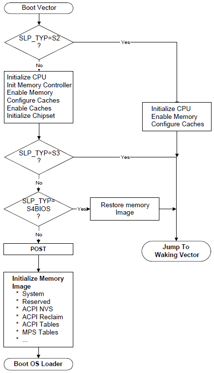
Fig. 16.2 Platform Firmware Initialization
The processor will start executing at its power-on reset vector when waking from an S2, S3, or S4 sleeping state, during a power-on sequence, or as a result of a hard or soft reset.
When executing from the power-on reset vector as a result of a power-on sequence, a hard or soft reset, or waking from an S4 sleep state, the platform firmware performs complete hardware initialization; placing the system in a boot configuration. The firmware then passes control to the operating system boot loader.
When executing from the power-on reset vector as a result of waking from an S2 or S3 sleep state, the platform firmware performs only the hardware initialization required to restore the system to either the state the platform was in prior to the initial operating system boot, or to the pre-sleep configuration state. In multiprocessor systems, non-boot processors should be placed in the same state as prior to the initial operating system boot. The platform firmware then passes control back to OSPM system by jumping to either the Firmware_Waking_Vector or the X_Firmware_Waking_Vector in the FACS (see Firmware ACPI Control Structure (FACS) for more information). The contents of operating system memory contents may not be changed during the S2 or S3 sleep state.
First, the platform runtime firmware determines whether this is a wake from S2 or S3 by examining the SLP_TYP register value, which is preserved between sleeping sessions. If this is an S2 or S3 wake, then the platform runtime firmware restores minimum context of the system before jumping to the waking vector. This includes:
- CPU configuration.
Platform runtime firmware restores the pre-sleep configuration or initial boot configuration of each CPU (MSR, MTRR, firmware update, SMBase, and so on). Interrupts must be disabled (for IA-32 processors, disabled by CLI instruction).
- Memory controller configuration.
the configuration is lost during the sleeping state, the platform runtime firmware initializes the memory controller to its pre-sleep configuration or initial boot configuration.
- Cache memory configuration.
If the configuration is lost during the sleeping state, the platform runtime firmware initializes the cache controller to its pre-sleep configuration or initial boot configuration.
- Functional device configuration.
The platform runtime firmware doesn’t need to configure/restore context of functional devices such as a network interface (even if it is physically included in chipset) or interrupt controller. OSPM is responsible for restoring all context of these devices. The only requirement for the hardware and platform runtime firmware is to ensure that interrupts are not asserted by devices when the control is passed to OS.
- ACPI registers.
SCI_EN bit must be set on non-HW-reduced ACPI platforms, and all event status/enable bits (PM1x_STS, PM1x_EN, GPEx_STS and GPEx_EN) must not be changed by platform runtime firmware.
Note
The platform runtime firmware may reconfigure the CPU, memory controller, and cache memory controller to either the pre-sleeping configuration or the initial boot configuration. OSPM must ccommodate both configurations.
When waking from an S4BIOS sleeping state, the platform boot firmware initializes a minimum number of devices such as CPU, memory, cache, chipset and boot devices. After initializing these devices, the platform boot firmware restores memory context from non-volatile memory such as hard disk, and jumps to waking vector.
As mentioned previously, waking from an S4 state is treated the same as a cold boot: the platform boot firmware runs POST and then initializes memory to contain the ACPI system description tables. After it has finished this, it can call OSPM loader, and control is passed to OSPM.
When waking from S4 (either S4OS or S4BIOS), the platform boot firmware may optionally set SCI_EN bit before passing control to OSPM. In this case, interrupts must be disabled (for IA-32 processors, disabled CLI instruction) until the control is passed to OSPM and the chipset must be configured in ACPI mode.
16.3.1. Placing the System in ACPI Mode
When a platform initializes from a cold boot (mechanical off or from an S4 or S5 state), the hardware platform may be configured in a legacy configuration, if not a HW-reduced ACPI platform. From these states, the platform boot firmware software initializes the computer as it would for a legacy operating system. When control is passed to the operating system, OSPM will check the SCI_EN bit and if it is not set will then enable ACPI mode by first finding the ACPI tables, and then by generating a write of the ACPI_ENABLE value to the SMI_CMD port (as described in the FADT). The hardware platform will set the SCI_EN bit to indicate to OSPM that the hardware platform is now configured for ACPI.
Note
Before SCI is enabled, no SCI interrupt can occur. Nor can any SCI interrupt occur immediately after ACPI is on. The SCI interrupt can only be signaled after OSPM has enabled one of the GPE/PM1 enable bits.
When the platform is waking from an S1, S2 or S3 state, and from S4 and S5 on HW-reduced ACPI platforms, OSPM assumes the hardware is already in the ACPI mode and will not issue an ACPI_ENABLE command to the SMI_CMD port
16.3.2. Platform Boot Firmware Initialization of Memory
During a power-on reset, an exit from an S4 sleeping state, or an exit from an S5 soft-off state, the platform boot firmware needs to initialize memory. This section explains how the platform boot firmware should configure memory for use by a number of features including:
ACPI tables.
Platform firmware memory that wants to be saved across S4 sleeping sessions and should be cached.
Platform firmware memory that does not require saving and should be cached.
For example, the configuration of the platform’s cache controller requires an area of memory to store the configuration data. During the wake sequence, the platform boot firmware will re-enable the memory controller and can then use its configuration data to reconfigure the cache controllers. To support these three items, IA-PC-based systems contain System Address Map Interfaces that return the following memory range types:
- ACPI Reclaim Memory.
Memory identified by the platform boot firmware that contains the ACPI tables. This memory can be any place above 8 MB and contains the ACPI tables. When OSPM is finished using the ACPI tables, it is free to reclaim this memory for system software use (application space).
- ACPI Non-Volatile-Sleeping Memory (NVS).
Memory identified by the BIOS as being reserved by the platform boot firmware for its use. OSPM is required to tag this memory as cacheable, and to save and restore its image before entering an S4 state. Except as directed by control methods, OSPM is not allowed to use this physical memory. OSPM will call the _PTS control method some time before entering a sleeping state, to allow the platform’s AML code to update this memory image before entering the sleeping state. After the system awakes from an S4 state, OSPM will restore this memory area and call the _WAK control method to enable the platform boot firmware to reclaim its memory image.
Note
The memory information returned from the system address map reporting interfaces should be the same before and after an S4 sleep.
When the system is first booting, OSPM will invoke E820 interfaces on IA-PC-based legacy systems or the GetMemoryMap() interface on UEFI-enabled systems to obtain a system memory map, System Address Map Interfaces for more information). As an example, the following memory map represents a typical IA-PC-based legacy platform’s physical memory map.
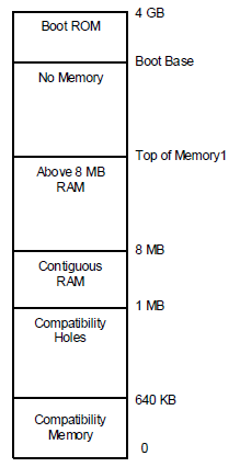
Fig. 16.3 Example Physical Memory Map
The names and attributes of the different memory regions are listed below:
0-640 KB. Compatibility Memory. Application executable memory for an 8086 system.
640 KB-1 MB. Compatibility Holes. Holes within memory space that allow accesses to be directed to the PC-compatible frame buffer (A0000h-BFFFFh), to adapter ROM space (C0000h-DFFFFh), and to system platform firmware space (E0000h-FFFFFh).
1 MB-8 MB. Contiguous RAM. An area of contiguous physical memory addresses. Operating systems may require this memory to be contiguous in order for its loader to load the OS properly on boot up. (No memory-mapped I/O devices should be mapped into this area.)
8 MB-Top of Memory1. This area contains memory to the “top of memory1” boundary. In this area, memory-mapped I/O blocks are possible.
Boot Base-4 GB. This area contains the bootstrap ROM.
The platform boot firmware should decide where the different memory structures belong, and then configure the E820 handler to return the appropriate values.
For this example, the platform boot firmware will report the system memory map by E820 as shown in Figure 15-4. Notice that the memory range from 1 MB to top of memory is marked as system memory, and then a small range is additionally marked as ACPI reclaim memory. A legacy OS that does not support the E820 extensions will ignore the extended memory range calls and correctly mark that memory as system memory.
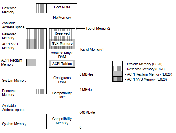
Fig. 16.4 Memory as Configured after Boot
Also, from the Top of Memory1 to the Top of Memory2, the platform boot firmware has set aside some memory for its own use and has marked as reserved both ACPI NVS Memory and Reserved Memory. A legacy OS will throw out the ACPI NVS Memory and correctly mark this as reserved memory (thus preventing this memory range from being allocated to any add-in device).
OSPM will call the _PTS control method prior to initiating a sleep (by programming the sleep type, followed by setting the SLP_EN bit). During a catastrophic failure (where the integrity of the AML code interpreter or driver structure is questionable), if OSPM decides to shut the system off, it will not issue a _PTS, but will immediately issue a SLP_TYP of “soft off” and then set the SLP_EN bit, or directly write the HW-reduced ACPI Sleep Type value and the SLP_EN bit to the Sleep Control Register. Hence, the hardware should not rely solely on the _PTS control method to sequence the system to the “soft off” state. After waking from an S4 state, OSPM will restore the ACPI NVS memory image and then issue the _WAK control method that informs platform runtime firmware that its memory image is back.
16.3.3. OS Loading
At this point, the platform boot firmware has passed control to OSPM, either by using OSPM boot loader (a result of waking from an S4/S5 or boot condition) or OSPM waking vector (a result of waking from an S2 or S3 state). For the Boot OS Loader path, OSPM will get the system address map via one of the mechanisms describe in System Address Map Interfaces If OSPM is booting from an S4 state, it will then check the NVS image file’s hardware signature with the hardware signature within the FACS table (built by platform boot firmware) to determine whether it has changed since entering the sleeping state (indicating that the platforms fundamental hardware configuration has changed during the current sleeping state). If the signature has changed, OSPM will not restore the system context and can boot from scratch (from the S4 state). Next, for an S4 wake, OSPM will check the NVS file to see whether it is valid. If valid, then OSPM will load the NVS image into system memory. Next, if not a HW-reduced ACPI platform, OSPM will check the SCI_EN bit and if it is not set, will write the ACPI_ENABLE value to the SMI_CMD register to switch into the system into ACPI mode and will then reload the memory image from the NVS file.
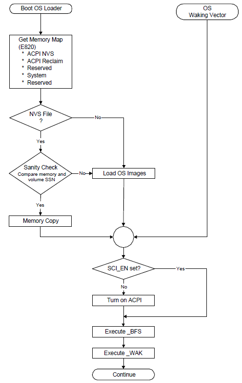
Fig. 16.5 OS Initialization
If an NVS image file did not exist, then OSPM loader will load OSPM from scratch. At this point, OSPM will generate a _WAK call that indicates to the platform runtime firmware that its ACPI NVS memory image has been successfully and completely updated.
16.3.4. Exiting ACPI Mode
For machines that do not boot in ACPI mode, ACPI provides a mechanism that enables the OS to disable ACPI. The following occurs:
OSPM unloads all ACPI drivers (including the ACPI driver).
OSPM disables all ACPI events.
OSPM finishes using all ACPI registers.
OSPM issues an I/O access to the port at the address contained in the SMI_CMD field (in the FADT) with the value contained in the ACPI_DISABLE field (in the FADT).
Platform runtime firmware then remaps all SCI events to legacy events and resets the SCI_EN bit.
Upon seeing the SCI_EN bit cleared, the ACPI OS enters the legacy OS mode.
When and if the legacy OS returns control to the ACPI OS, if the legacy OS has not maintained the ACPI tables (in reserved memory and ACPI NVS memory), the ACPI OS will reboot the system to allow the platform runtime firmware to re-initialize the tables.