B. Appendix B: Video Extensions
B.1. ACPI Extensions for Display Adapters: Introduction
This section of the document describes a number of specialized ACPI methods to support motherboard graphics devices.
In many cases, system manufacturers need to add special support to handle multiple output devices such as panels and TV-out capabilities, as well as special power management features. This is particularly true for notebook manufacturers. The methods described here have been designed to enable interaction between the platform firmware, video driver, and OS to smoothly support these features.
Systems containing a built-in display adapter are required to implement the ACPI Extensions for Display Adapters.
Table B-1: Video Extension Object Requirements
Method |
Description |
Requirement |
_DOS |
Enable/Disable output switching |
Required if system supports display switching or LCD brightness levels |
_DOD |
Enumerate all devices attached to display adapter |
Required if integrated controller supports output switching |
_ROM |
Get ROM Data |
Required if ROM image is stored in proprietary format |
_GPD |
Get POST Device |
Required if _VPO is implemented |
_SPD |
Set POST Device |
Required if _VPO is implemented |
_VPO |
Video POST Options |
Required if system supports changing post VGA device |
_ADR |
Return the unique ID for this device |
Required |
_BCL |
Query list of brightness control levels supported |
Required if embedded LCD supports brightness control |
_BCM |
Set the brightness level |
Required if _BCL is implemented |
_DDC |
Return the EDID for this device |
Required if embedded LCD does not support return of EDID via standard interface |
_DCS |
Return status of output device |
Required if the system supports display switching (via hotkey) |
_DGS |
Query graphics state |
Required if the system supports display switching (via hotkey |
_DSS |
Device state set |
Required if the system supports display switching (via hotkey). |
B.2. Video Extension Definitions
- Built-in display adapter
This is a graphics chip that is built into the motherboard and cannot be replaced. ACPI information is valid for such built-in devices.
- Add-in display adapter
This is a graphics chip or board that can be added to or removed from the computer. Because the platform firmware cannot have specific knowledge of add-in boards, ACPI information is not available for add-in devices.
- Boot-up display adapter
This is the display adapter programmed by the platform boot firmware during machine power-on self-test (POST). It is the device upon which the machine will show the initial operating system boot screen, as well as any platform boot firmware messages.
The system can change the boot-up display adapter, and it can switch between the built-in adapter and the add-in adapter.
- Display device
This is a synonym for the term display adapter discussed above.
- Output device
This is a device, which is a recipient of the output of a display device. For example, a CRT or a TV is an output device.
B.3. ACPI Namespace
This is an example of the display-related namespace on an ACPI system:
GPE          // ACPI General-purpose HW event
    _L0x     // Notify(VGA, 0x80) to tell OSPM of the event, when user presses
             // the hot key to switch the output status of the monitor.
             // Notify(VGA, 0x81) to tell the event to OSPM, when there are any
             // changes on the sub-devices for the VGA controller

SB
|- PCI
    |- VGA              // Define the VGA controller in the namespace
        |- \_PS0 / PR0
        |- \_PS1 / PR1
        |- \_PS3
        |- \_DOS        // Method to control display output switching
        |- \_DOD        // Method to retrieve information about child output devices
        |- \_ROM        // Method to retrieve the ROM image for this device
        |- \_GPD        // Method for determining which VGA device will post
        |- \_SPD        // Method for controlling which VGA device will post
        |- \_VPO        // Method for determining the post options
        |- CRT          // Child device CRT
            |- \_ADR    // Hardware ID for this device
            |- \_DDC    // Get EDID information from the monitor device
            |- \_DCS    // Get current hardware status
            |- \_DGS    // Query desired hardware active \ inactive state
            |- \_DSS    // Set hardware active \ inactive state
            |- \_PS0  \
            |- \_PS1    - Power methods
            |- \_PS2    - for the output device
            |- \_PS3  /
        |- LCD          // Child device LCD
            |- \_ADR    // Hardware ID for this device
            |- \_DDC    // Get EDID information from the monitor device
            |- \_DCS    // Get current hardware status
            |- \_DGS    // Query desired hardware active \ inactive state
            |- \_DSS    // Set hardware active \ inactive state
            |- \_BCL    // Brightness control levels
            |- \_BCM    // Brightness control method
            |- \_BQC    // Brightness Query Current Level
            |- \_PS0  \
            |- \_PS1    - Power methods
            |- \_PS2    - for the output device
            |- \_PS3  /
        |- TV           // Child Device TV
            |- \_ADR    // Hardware ID for this device
            |- \_DDC    // Get EDID information from the monitor device
            |- \_DCS    // Get current hardware status
            |- \_DGS    // Query desired hardware active \ inactive state
            |- \_DSS    // Set hardware active \ inactive state
The LCD device represents the built-in output device. Mobile PCs will always have a built-in LCD display, but desktop systems that have a built-in graphics adapter generally don’t have a built-in output device.
B.4. Display-specific Methods
The methods described in this section are all associated with specific display devices. This device-specific association is represented in the namespace example in the previous section by the positioning of these methods in a device tree.
B.4.1. _DOS (Enable/Disable Output Switching)
Many ACPI machines currently reprogram the active display output automatically when the user presses the display toggle switch on the keyboard. This is done because most video device drivers are currently not capable of being notified synchronously of such state changes. However, this behavior violates the ACPI specification, because the system modifies some graphics device registers.
The existence of the _DOS method indicates that the platform runtime firmware is capable of automatically switching the active display output or controlling the brightness of the LCD. If it exists at all, the _DOS method must be present for all display output devices. This method is required if the system supports display switching or LCD brightness control.
Arguments:(1)
Arg0 - An Integer containing the encoded switching controls (see below)
Return Value:
None
Additional Argument Information:
Bits [1:0]:
0 - The platform runtime firmware should not automatically switch
(toggle) the active display output, but instead just save the desired
state change for the display output devices in variables associated with
each display output, and generate the display switch event. OSPM can
query these state changes by calling the \_DGS method.

1 - The platform runtime firmware should automatically switch (toggle)
the active display output, with no interaction required on the OS part.
The display switch event should not be generated in this case.

2 - The \_DGS values should be locked. It's highly recommended that the
platform runtime firmware do nothing when hotkey pressed. No switch, no
notification.

3 - The platform runtime firmware should not automatically switch
(toggle) the active display output, but instead generate the display
switch event notify codes 0x82, 0x83, or 0x84. OSPM will determine what
display output state should be set, and change the display output state
without further involvement from the platform runtime firmware.
Bit [2]:
0 - The platform runtime firmware should automatically control the
brightness level of the LCD when the power changes from AC to DC.

1 - The platform runtime firmware should not automatically control the
brightness level of the LCD when the power changes from AC to DC.
The _DOS method controls this automatic switching behavior. This method should do so by saving the parameter passed to this method in a global variable somewhere in the platform runtime firmware data segment. The platform runtime firmware then checks the value of this variable when doing display switching. This method is also used to control the generation of the display switching Notify (VGA, 0x80/0x81).
The platform runtime firmware, when doing switching of the active display, must verify the state of the variable set by the _DOS method. The default value of this variable must be 1.
B.4.2. _DOD (Enumerate All Devices Attached to the Display Adapter)
This method is used to enumerate devices attached to the display adapter. This method is required if integrated controller supports output switching.
On many laptops today, a number of devices can be connected to the graphics adapter in the machine. These devices are on the motherboard and generally are not directly enumerable by the video driver; for this reason, all motherboard VGA attached devices are listed in the ACPI namespace.
These devices fall into two categories:
Video output devices. For example, a machine with a single display device on the motherboard can have three possible output devices attached to it, such as a TV, a CRT, or a panel.
Non-video output devices. For example, TV Tuner, DVD decoder, Video Capture. They just attach to VGA and their power management closely relates to VGA.
Both ACPI and the video driver have the ability to program and configure output devices. This means that both ACPI and the video driver must enumerate the devices using the same IDs. To solve this problem, the _DOD method returns a list of devices attached to the graphics adapter, along with device-specific configuration information. This information will allow the cooperation between ACPI components and the video driver.
Every child device enumerated in the ACPI namespace under the graphics adapter must be specified in this list of devices. Each display device must have its own ID, which is unique with respect to any other attachable devices enumerated.
Arguments:
None
Return Value:
A Package containing a variable-length list of Integers, each of which contains the 32-bit device attribute of a child device (See Table B-2 below).
Example
Method (_DOD, 0) {
   Return (
      Package()
      {
         0x00000110, // Primary LCD panel, not detectable by firmware
         0x80000100, // CRT type display, not detectable by firmware
         0x80000220, // TV type display, not detectable by the firmware
         0x80000411, // Secondary LCD panel, not detectable by firmware
      }
   )
}
Table B-2: Video Output Device Attributes
Bits |
Definition |
15:0 |
Device ID. The device ID must match the ID’s specified by Video Chip Vendors. They must also be unique under VGA namespace:
Bits [3:0] Display Index: A zero-based instance of the Display, when multiple displays of the same type are attached, regardless of where it is associated. Starting from the first adapter and its first display of the type on the first integrated internal device and then incrementing per device-function according to its relative port number.
Bits [7:4] Display Port Attachment: This field differentiates displays of the same type attached at different points of one adapter. The zero-based number scheme is specific to each Video Chip Vendors’ implementation.
Bits [11:8] Display Type: Decribes the specific type of Display Technology in use.
0 – Other
1 – VGA* CRT or VESA* Compatible Analog Monitor
2 – TV/HDTV or other Analog-Video Monitor
3 – External Digital Monitor (see note 1)
4 – Internal/Integrated Digital Flat Panel (see note 2)
5-15 – Reserved for future use
Bits [15:12] Chipset-vendor specific
|
16 |
Platform boot firmware can detect the device. |
17 |
Non-VGA output device whose power is related to the VGA device. This can be used when specifying devices like TV Tuner, DVD decoder, Video Capture … etc. |
20:18 |
For VGA multiple-head devices, this specifies head or pipe ID e.g. for Dual-Pipe*, Dual-Display*, Duo-View*, TwinView*, Triple-View* … etc, beginning with 0 for head 0 or single-head device and increasing for each additional head. |
30:21 |
Reserved (must be 0) |
31 |
Device ID Scheme:
1 - Uses the bit-field definitions above (bits 15:0)
0 - Other scheme, contact the Video Chip Vendor
|
Note
1: An “External Digital Monitor” is an external display device attachable via a user-accessible connector standard (e.g. DFP* or DVI* Compatible Monitors).
2: An “Internal Flat Panel” is a non-detachable fixed pixel display device, including a backlight, and is internally associated, without user-accessible connectors, to the Video Chip (e.g. TFT LCD via TMDS*, LVDS* interface).
As mentioned in the above table, a “Pipe” or “Head” refers to a unique display content stream e.g. at a particular color-depth, resolution, and refresh-rate. The “Port” refers to the display output device attachment and may include a DAC, encoder or other mechanism required to support a given display end-point. The “Display Type” describes the generalized class of display output technology, and the means of integration. The “Display Index” is then an index that assists in creating a unique identifier display end-points in scenarios where other attributes are the same.
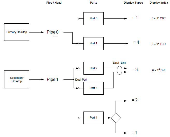
Fig. B-1: Example Display Architecture
Table B-3: Example Device IDs
Bits |
Definition |
0x000xyyyy |
Bit [31] = 0. Other proprietary scheme - 0x110 Device ID is an exception (see note 3) |
0x00000110 |
Integrated LCD Panel #1 using a common, backwards compatible ID |
0x80000100 |
Integrated VGA CRT or VESA compatible Monitor #1 on Port0 |
0x80000240 |
Integrated TV #1 on Port4 |
0x80000410 |
Integrated Internal LCD Panel #1 on Port1 |
0x80000421 |
LVDS Panel #2 Dual-Link using Port2 & 3 (see note 4) |
0x80000131 |
VGA CRT or VESA compatible Monitor #2 on Port3 |
0x80000121 |
Dual-Link VGA CRT or VESA compatible Monitor #2 using Port2 & 3 (see note 4) |
0x80000320 |
DVI Monitor #1 on Port2 (shares Port2 with a Dual-Function DVI/TV Encoder) (see note 5) |
0x80000331 |
DVI Monitor #2 on Port3 |
0x80000330 |
Dual-Link DVI Monitor #1 using Port2 & 3 |
0x80000231 |
TV #2 on Port2 (shares Port2 with a Dual-Function DVI/TV Encoder) (see note 5) |
Note
3: When Bit [31] is 0, no assumptions can be made on which ID will be used for any particular display type. Contact the Video Chip vendor for details of the ID scheme employed.
4: In certain cases multiple Displays Ports may be combined to increase bandwidth for a particular Display in higher-resolution modes. In this situation, the Display Type and Port Number should remain the same in order to retain a consistent ID for the same device, regardless of the selected display mode.
5: In certain cases, more than one type of display (and connector) may be supportable on a single Port (e.g. DVI + TV + CRT on a single Display Encoder device), while only one display is selectable at any time. In this case, the Port Number field of the ID may be the same as other Display IDs, however the other fields (e.g. Display Type) provide uniqueness.
B.4.3. _ROM (Get ROM Data)
This method is used to get a copy of the display devices’ ROM data. This method is required when the ROM image is stored in a proprietary format such as stored in the platform firmware ROM. This method is not necessary if the ROM image can be read through a standard PCI interface (using ROM BAR). If _ROM is present, it is preferred over the image read through the standard PCI interface, in order to allow platform runtime firmware to provide re-configured ROM data via the method.
The video driver can use the data returned by this method to program the device. The format of the data returned by this function is a large linear buffer limited to 4 KB. The content of the buffer is defined by the graphics independent hardware vendor (IHV) that builds this device. The format of this ROM data will traditionally be compatible with the ROM format of the normal PCI video card, which will allow the video driver to program its device, independently of motherboard versus add-in card issues.
The data returned by the _ROM method is implementation-specific data that the video driver needs to program the device. This method is defined to provide this data as motherboard devices typically don’t have a dedicated option ROM. This method will allow a video driver to get the key implementation specific data it needs so that it can fully control and program the device without platform runtime firmware support.
Arguments:(2)
Arg0 - An Integer containing the offset of the display device ROM data
Arg1 - An Integer containing the size of the buffer to fill in (up to 4K).
Return Value:
A Buffer containing the requested ROM data
B.4.4. _GPD (Get POST Device)
This method is required if the _VPO method is implemented.
This method is used as a mechanism for the OS to query a CMOS value that determines which VGA device will be posted at boot. A zero return value indicates the motherboard VGA will be posted on the next boot, a 1 indicates a PCI VGA device will be posted, and a 2 indicates an AGP VGA device will be posted.
Arguments:
None
Return Value:
An Integer containing encoded post information (32 bits valid):
Bits [1:0]
  00 - Post the motherboard VGA device
  01 - Post an add-in PCI VGA device
  10 - Post an add-in AGP VGA device
  11 - Post an add-in PCI-Express VGA device
Bits [31:2] - Reserved (must be 0)
B.4.5. _SPD (Set POST Device)
This method is required if the _VPO method is implemented.
This method is used as a mechanism for the OS to update a CMOS value that determines which video device will be posted at boot. A zero argument will cause the “motherboard” to be posted on the next boot, a 1 will cause an add-in PCI device to be posted, and a 2 will cause an add-in AGP device to be posted.
Arguments:(1)
Arg0 - An Integer containing encode post information (32 bits valid):
Bits [1:0]
  00 - Post the motherboard VGA device
  01 - Post an add-in PCI VGA device
  10 - Post an add-in AGP VGA device
  11 - Post an add-in PCI-Express VGA device
Bits [31:2] - Reserved (must be 0)
Return Value:
An Integer containing the status of the operation:
0 - Operation was successful
Non-zero - Operation failed
Example:
Method (_SPD, 1) { // Make the motherboard device the device to post }
B.4.6. _VPO (Video POST Options)
This method is required for systems with video devices built onto the motherboard and support changing post-VGA device.
This method is used as a mechanism for the OS to determine what options are implemented. This method will be used in conjunction with _GPD and _SPD.
Arguments:
None
Return Value:
An Integer containing the options that are implemented and available:
Bit [0] - Posting the motherboard VGA device is an option.
          (Bit [0] should always be set)
Bit [1] - Posting a PCI VGA device is an option.
Bit [2] - Posting an AGP VGA device is an option.
Bit [3] - Posting a PCI-Express VGA device is an option.
Bits [31:4] - Reserved (must be zero)
B.5. Notifications for Display Devices
Display devices may need to know about external, asynchronous events. In order to accommodate that, the following notifications are defined.
The event number is standardized because the event will be handled by the OS directly under certain circumstances (see _DOS method in this specification).
These notifications are valid for Display Devices
Table B-4: Notifications for Display Devices
Value |
Description |
0x80 |
Cycle Output Device. Used to notify OSPM whenever the state of one of the output devices attached to the VGA controller has been switched or toggled. This event will, for example, be generated when the user presses a hotkey to switch the active display output from the LCD panel to the CRT. |
0x81 |
Output Device Status Change. Used to notify OSPM whenever the state of any output devices attached to the VGA controller has been changed. This event will, for example, be generated when the user plugs-in or remove a CRT from the VGA port. In this case, OSPM will re-enumerate all devices attached to VGA |
0x82 |
Cycle Display Output Hotkey Pressed. Used to notify OSPM whenever the user has pressed the Cycle display hotkey. |
0x83 |
Next Display Output Hotkey Pressed. Used to notify OSPM whenever the user has pressed the Next display hotkey. |
0x84 |
Previous Display Output Hotkey Pressed. Used to notify OSPM whenever the user has pressed the Previous display hotkey. |
B.6. Output Device-specific Methods
The methods in this section are methods associated with the display output device.
B.6.1. _ADR (Return the Unique ID for this Device)
This method returns a unique ID representing the display output device. All output devices must have a unique hardware ID. This method is required for all The IDs returned by this method will appear in the list of hardware IDs returned by the _DOD method.
Arguments:
None
Return Value:
An Integer containing the device ID (32 bits)
Example:
Method (_ADR, 0) {
return(0x0100)             // device ID for this CRT
}
This method is required for all output display devices.
B.6.2. _BCL (Query List of Brightness Control Levels Supported)
This method allows the OS to query a list of brightness level supported by built-in display output devices. (This method in not allowed for externally connected displays.) This method is required if an integrated LCD is present and supports brightness levels.
Each brightness level is represented by a number between 0 and 100, and can be thought of as a percentage. For example, 50 can be 50% power consumption or 50% brightness, as defined by the OEM.
The OEM may define the number 0 as “Zero brightness” that can mean to turn off the lighting (e.g. LCD panel backlight) in the device. This may be useful in the case of an output device that can still be viewed using only ambient light, for example, a transflective LCD. If Notify(Output Device, 0x85) for “Zero brightness” is issued, OSPM may be able to turn off the lighting by calling _BCM(0).
Arguments:
None
Return Value:
A variable-length Package containing a list of Integers representing the the supported brightness levels. Each integer has 8 bits of significant data.
Example:
Method (_BCL, 0) {
                             // List of supported brightness levels
   Return (Package(7){
      80,                    // level when machine has full power
      50,                    // level when machine is on batteries
                             // other supported levels:
      20, 40, 60, 80, 100}
}
The first number in the package is the level of the panel when full power is connected to the machine. The second number in the package is the level of the panel when the machine is on batteries. All other numbers are treated as a list of levels OSPM will cycle through when the user toggles (via a keystroke) the brightness level of the display.
These levels will be set using the _BCM method described in the following section.
B.6.3. _BCM (Set the Brightness Level)
This method allows OSPM to set the brightness level of a built-in display output device.
The OS will only set levels that were reported via the _BCL method. This method is required if _BCL is implemented.
Arguments:(1)
Arg0 - An Integer containing the new brightness level
Return Value:
None
Example:
Method (_BCM, 1) { // Set the requested level }
The method will be called in response to a power source change or at the specific request of the end user, for example, when the user presses a function key that represents brightness control.
B.6.4. _BQC (Brightness Query Current level)
This optional method returns the current brightness level of a built-in display output device. If present, it must be set by the platform for initial brightness.
Arguments:
None
Return Value:
An Integer containing the current brightness level (must be one of the values returned from the _BCL method)
B.6.5. _DDC (Return the EDID for this Device)
This method returns an EDID (Extended Display Identification Data) structure that represents the display output device. This method is required for integrated LCDs that do not have another standard mechanism for returning EDID data.
Arguments:
Arg0 - An Integer containing a code for the return data length:
1 - Return 128 bytes of data
2 - Return 256 bytes of data
3 – Return 384 bytes of data
4 – Return 512 bytes of data
Return Value:
Either a Buffer containing the requested data (of the length specified in Arg0), or an Integer (value 0) if Arg0 was invalid
Example:
Method (_DDC, 2) {
   (LEqual (Arg0, 1)) { Return (Buffer(128){ ,,,, }) }
   If (LEqual (Arg0, 2)) { Return (Buffer(256){ ,,,, }) }
   Return (0)
}
The buffer will later be interpreted as an EDID data block. The format of this data is defined by the VESA EDID specification.
B.6.6. _DCS (Return the Status of Output Device)
This method is required if hotkey display switching is supported.
Arguments:
None
Return Value:
An Integer containing the device status (32 bits) (see Table B-5 below).
Table B-5: Output Device Status
Bits |
Definition |
0 |
Output connector exists in the system now |
1 |
Output is activated |
2 |
Output is ready to switch |
3 |
Output is not defective (it is functioning properly) |
4 |
Device is attached (this is optional) |
31:5 |
Reserved (must be zero) |
Example:
If the output signal is activated by _DSS, _DCS returns 0x1F or 0x0F.
If the output signal is inactivated by _DSS, _DCS returns 0x1D or 0x0D.
If the device is not attached or cannot be detected, _DCS returns 0x0xxxx and should return 0x1xxxx if it is attached.
If the output signal cannot be activated, _ DCS returns 0x1B or 0x0B.
If the output connector does not exist (when undocked), _DCS returns 0x00.
B.6.7. _DGS (Query Graphics State)
This method is used to query the state (active or inactive) of the output device. This method is required if hotkey display switching is supported.
Arguments:
None
Return Value:
An Integer containing the device state (32 bits) (see Table B-6 below)
Table B-6: Device State for _DGS
Bits |
Definition |
0 |
0 - Next desired state is inactive / 1 - Next desired state is active |
31:1 |
Reserved (must be zero) |
The desired state represents what the user wants to activate or deactivate, based on the special function keys the user pressed. OSPM will query the desired state when it receives the display toggle event (described earlier).
B.6.8. _DSS (Device Set State)
OSPM will call this method when it determines the outputs can be activated or deactivated. OSPM will manage this to avoid flickering as much as possible. This method is required if hotkey display switching is supported.
Arguments:(1)
Arg0 - An Integer containing the new device state (32 bits) (see Table B-7 below)
Return Value:
None
Table B-7: Device State for _DSS
Bits |
Definition |
0 |
0 - Set output device to inactive state 1 - Set output device to active state |
30 |
0 - Do whatever Bit [31] requires 1 - Don’t do actual switching, but need to change _DGS to next state |
31 |
0 - Don’t do actual switching, just cache the change 1 - If Bit [30] = 0, commit actual switching, including any _DSS with MSB=0 called before If Bit [30] = 1, don’t do actual switching, change _DGS to next state |
29:1 |
Reserved (must be zero) |
Example Usage:
OS may call in such an order to turn off CRT, and turn on LCD:
CRT._DSS(0);
LCD._DSS(80000001L);

or:

LCD._DSS(1);
CRT._DSS(80000000L);
OS may call in such an order to force platform runtime firmware to make _DGS jump to next state without actual CRT, LCD switching:
CRT._DSS(40000000L);
LCD._DSS(C0000001L);
B.7. Notifications Specific to Output Devices
Output devices may need to know about external, asynchronous events. In order, each of these events corresponds to accommodate that, pressing a key or button on the following machine. Using these notifications is not appropriate if no physical device exists that is associated with them. OSPM may ignore any of these notifications if, for example the current user does not have permission to change the state of the output device. These notifications are only valid for Output Devices.
Table B-8: Notification Values for Output Devices
Value |
Description |
0x85 |
Cycle Brightness. Used to notify OSPM that the output device brightness should be increased by one level. Used to notify OSPM that the user pressed a button or key that is associated with cycling brightness. A useful response by OSPM would be to increase output device brightness by one or more levels. (Levels are defined in _BCL.) If the brightness level is currently at the maximum value, it should be set to the minimum level. |
0x86 |
Increase Brightness. Used to notify OSPM that the output device brightness should be increased by one or more levels as defined by the _BCL object. Used to notify OSPM that the user pressed a button or key that is associated with increasing brightness. If the brightness level is currently at the maximum value, OSPM may should ignore the notification. |
0x87 |
Decrease Brightness. Used to notify OSPM that the output device brightness should be decreased by one or more levels as defined by the _BCL object. Used to notify OSPM that the user pressed a button or key that is associated with decreasing device brightness. If the brightness level is currently at the minimum value, OSPM may should ignore the notification. |
0x88 |
Zero Brightness. Used to notify OSPM that the output device brightness should be zeroed, effectively turning off any lighting that is associated with the device. Used to notify OSPM that the user pressed a button or key associated with zeroing device brightness. This is not to be confused with putting the device in a D3 state. While the brightness may be decreased to zero, the device may still be displaying, using only ambient light. |
0x89 |
Display Device Off. Used to notify OSPM that the device should be put in an off state, one that is not active or visible to the user, usually D3, but possibly D1 or D2. Used to notify OSPM that the user pressed a low power button or key associated with putting the device in an off state. There is no need for a corresponding “device on” notification, for two reasons. First, OSPM may choose to toggle device state when this event is pressed multiple times. Second, OSPM may (and probably will) choose to turn the monitor on whenever the user types on the keyboard, moves the mouse, or otherwise indicates that he or she is attempting to interact with the machine. |
B.8. Notes on State Changes
It is possible to have any number of simultaneous active output devices. It is possible to have 0, 1, 2 … and so on active output devices. For example, it is possible for both the LCD device and the CRT device to be active simultaneously. It is also possible for all display outputs devices to be inactive (this could happen in a system where multiple graphics cards are present).
The state of the output device is separate from the power state of the device. The “active” state represents whether the image being generated by the graphics adapter would be sent to this particular output device. A device can be powered off or in a low-power mode but still be the active output device. A device can also be in an off state but still be powered on.
Example of the display-switching mechanism:
The laptop has three output devices on the VGA adapter. At this moment in time, the panel and the TV are both active, while the CRT is inactive. The automatic display-switching capability has been disabled by OSPM by calling _DOS(0), represented by global variable display_switching = 0.
The platform runtime firmware, in order to track the state of these devices, will have three global variable to track the state of these devices. There are currently initialized to:
crt_active - 0 panel_active - 1 tv_active - 1
The user now presses the display toggle switch, which would switch the TV output to the CRT.
The platform runtime firmware first updates three temporary variables representing the desired state of output devices:
want_crt_active - 1 want_panel_active - 1 want_tv_active - 0
Then the platform runtime firmware checks the display_switching variable. Because this variable is set to zero, the platform runtime firmware does not do any device reprogramming, but instead generates a Notify (VGA, 0x80/0x81) event for the display. This event will be sent to OSPM.
OSPM will call the _DGS method for each enumerated output device to determine which devices should now be active. OSPM will determine whether this is possible, and will reconfigure the internal data structure of the OS to represent this state change. The graphics modes will be recomputed and reset.
Finally, OSPM will call the _DSS method for each output device it has reconfigured.
Note
OSPM may not have called the _DSS routines with the same values and the _DGS routines returned, because the user may be overriding the default behavior of the hardware-switching driver or operating system-provided UI. The data returned by the _DGS method (the want_XXX values) are only a hint to the OS as to what should happen with the output devices.
If the display-switching variable is set to 1, then the platform runtime firmware would not send the event, but instead would automatically reprogram the devices to switch outputs. Any legacy display notification mechanism could also be performed at this time.