8. Processor Configuration and Control
This section describes the configuration and control of the processor’s power and performance states. The major controls over the processors are:
Processor power states: C0, C1, C2, C3, … Cn
Processor clock throttling
Processor performance states: P0, P1, … Pn
These controls are used in combination by OSPM to achieve the desired balance of the following sometimes conflicting goals:
Performance
Power consumption and battery life
Thermal requirements
Noise-level requirements
Because the goals interact with each other, the operating software needs to implement a policy as to when and where tradeoffs between the goals are to be made (see note below). For example the operating software would determine when the audible noise of the fan is undesirable and would trade off that requirement for lower thermal requirements, which can lead to lower processing performance. Each processor configuration and control interface is discussed in the following sections along with how controls interacts with the various goals.
Note
A thermal warning leaves room for operating system tradeoffs (to start the fan or reduce performance), without issuing a critical thermal alert.
8.1. Processor Power States
ACPI defines the power state of system processors while in the G0 working state as being either active executing or sleeping (not executing) - see note below. Processor power states include are designated C0, C1, C2, C3, …Cn. The C0 power state is an active power state where the CPU executes instructions. The C1 through Cn power states are processor sleeping states where the processor consumes less power and dissipates less heat than leaving the processor in the C0 state. While in a sleeping state, the processor does not execute any instructions. Each processor sleeping state has a latency associated with entering and exiting that corresponds to the power savings. In general, the longer the entry/exit latency, the greater the power savings when in the state. To conserve power, OSPM places the processor into one of its supported sleeping states when idle. While in the C0 state, ACPI allows the performance of the processor to be altered through a defined “throttling” process and through transitions into multiple performance states (P-states). A diagram of processor power states is provided below.
Note
These CPU states map into the G0 working state, and the Cx states only apply to the G0 state. In the G3 sleeping state, the state of the CPU is undefined.
Fig. 8.1 Processor Power States
ACPI defines logic on a per-CPU basis that OSPM uses to transition between the different processor power states. This logic is optional, and is described through the FADT table and processor objects (contained in the hierarchical namespace). The fields and flags within the FADT table describe the symmetrical features of the hardware, and the processor object contains the location for the particular CPU’s clock logic (described by the P_BLK register block and _CST objects).
The P_LVL2 and P_LVL3 registers provide optional support for placing the system processors into the C2 or C3 states. The P_LVL2 register is used to sequence the selected processor into the C2 state, and the P_LVL3 register is used to sequence the selected processor into the C3 state. Additional support for the C3 state is provided through the bus master status and arbiter disable bits (BM_STS in the PM1_STS register and ARB_DIS in the PM2_CNT register). System software reads the P_LVL2 or P_LVL3 registers to enter the C2 or C3 power state. The Hardware must put the processor into the proper clock state precisely on the read operation to the appropriate P_LVLx register. The platform may alternatively define interfaces allowing OSPM to enter C-states using the _CST object, which is defined in _CST (C States).
Processor power state support is symmetric when presented via the FADT and P_BLK interfaces; OSPM assumes all processors in a system support the same power states. If processors have non-symmetric power state support, then the platform runtime firmware will choose and use the lowest common power states supported by all the processors in the system through the FADT table. For example, if the CPU0 processor supports all power states up to and including the C3 state, but the CPU1 processor only supports the C1 power state, then OSPM will only place idle processors into the C1 power state (CPU0 will never be put into the C2 or C3 power states). Notice that the C1 power state must be supported. The C2 and C3 power states are optional (see the PROC_C1 flag in the FADT table description in System Description Table Header).
The following sections describe processor power states in detail.
8.1.1. Processor Power State C0
While the processor is in the C0 power state, it executes instructions. While in the C0 power state, OSPM can generate a policy to run the processor at less than maximum performance. The clock throttling mechanism provides OSPM with the functionality to perform this task in addition to thermal control. The mechanism allows OSPM to program a value into a register that reduces the processor’s performance to a percentage of maximum performance.
Fig. 8.2 Throttling Example
The FADT contains the duty offset and duty width values. The duty offset value determines the offset within the P_CNT register of the duty value. The duty width value determines the number of bits used by the duty value (which determines the granularity of the throttling logic). The performance of the processor by the clock logic can be expressed with the following equation:

Fig. 8.3 Equation 1 Duty Cycle Equation
Nominal performance is defined as “close as possible, but not below the indicated performance level.” OSPM will use the duty offset and duty width to determine how to access the duty setting field. OSPM will then program the duty setting based on the thermal condition and desired power of the processor object. OSPM calculates the nominal performance of the processor using the equation expressed in Equation 1. Notice that a dutysetting of zero is reserved.For example, the clock logic could use the stop grant cycle to emulate a divided processor clock frequency on an IA processor (through the use of the STPCLK# signal). This signal internally stops the processor’s clock when asserted LOW. To implement logic that provides eight levels of clock control, the STPCLK# pin could be asserted as follows (to emulate the different frequency settings):
Fig. 8.4 Example Control for the STPCLK
To start the throttling logic OSPM sets the desired duty setting and then sets the THT_EN bit HIGH. To change the duty setting, OSPM will first reset the THT_EN bit LOW, then write another value to the duty setting field while preserving the other unused fields of this register, and then set the THT_EN bit HIGH again.
The example logic model is shown below:
Fig. 8.5 ACPI Clock Logic (One per Processor)
Implementation of the ACPI processor power state controls minimally requires the support a single CPU sleeping state (C1). All of the CPU power states occur in the G0/S0 system state; they have no meaning when the system transitions into the sleeping state(S1-S4). ACPI defines the attributes (semantics) of the different CPU states (defines four of them). It is up to the platform implementation to map an appropriate low-power CPU state to the defined ACPI CPU state.
ACPI clock control is supported through the optional processor register block (P_BLK). ACPI requires that there be a unique processor register block for each CPU in the system. Additionally, ACPI requires that the clock logic for multiprocessor systems be symmetrical when using the P_BLK and FADT interfaces; if the P0 processor supports the C1, C2, and C3 states, but P1 only supports the C1 state, then OSPM will limit all processors to enter the C1 state when idle.
The following sections define the different ACPI CPU sleeping states.
8.1.2. Processor Power State C1
All processors must support this power state. This state is supported through a native instruction of the processor (HLT for IA 32-bit processors), and assumes no hardware support is needed from the chipset. The hardware latency of this state must be low enough that OSPM does not consider the latency aspect of the state when deciding whether to use it. Aside from putting the processor in a power state, this state has no other software-visible effects. In the C1 power state, the processor is able to maintain the context of the system caches.
The hardware can exit this state for any reason, but must always exit this state when an interrupt is to be presented to the processor.
8.1.3. Processor Power State C2
This processor power state is optionally supported by the system. If present, the state offers improved power savings over the C1 state and is entered by using the P_LVL2 command register for the local processor or an alternative mechanism as indicated by the _CST object. The worst-case hardware latency for this state is declared in the FADT and OSPM can use this information to determine when the C1 state should be used instead of the C2 state. Aside from putting the processor in a power state, this state has no other software-visible effects. OSPM assumes the C2 power state has lower power and higher exit latency than the C1 power state.
The C2 power state is an optional ACPI clock state that needs chipset hardware support. This clock logic consists of an interface that can be manipulated to cause the processor complex to precisely transition into a C2 power state. In a C2 power state, the processor is assumed capable of keeping its caches coherent; for example, bus master and multiprocessor activity can take place without corrupting cache context.
The C2 state puts the processor into a low-power state optimized around multiprocessor and bus master systems. OSPM will cause an idle processor complex to enter a C2 state if there are bus masters or Multiple processor activity (which will prevent OSPM from placing the processor complex into the C3 state). The processor complex is able to snoop bus master or multiprocessor CPU accesses to memory while in the C2 state.
The hardware can exit this state for any reason, but must always exit this state whenever an interrupt is to be presented to the processor.
8.1.4. Processor Power State C3
This processor power state is optionally supported by the system. If present, the state offers improved power savings over the C1 and C2 state and is entered by using the P_LVL3 command register for the local processor or an alternative mechanism as indicated by the _CST object. The worst-case hardware latency for this state is declared in the FADT, and OSPM can use this information to determine when the C1 or C2 state should be used instead of the C3 state. While in the C3 state, the processor’s caches maintain state but the processor is not required to snoop bus master or multiprocessor CPU accesses to memory.
The hardware can exit this state for any reason, but must always exit this state when an interrupt is to be presented to the processor or when BM_RLD is set and a bus master is attempting to gain access to memory.
OSPM is responsible for ensuring that the caches maintain coherency. In a uniprocessor environment, this can be done by using the PM2_CNT.ARB_DIS bus master arbitration disable register to ensure bus master cycles do not occur while in the C3 state. In a multiprocessor environment, the processors’ caches can be flushed and invalidated such that no dynamic information remains in the caches before entering the C3 state.
There are two mechanisms for supporting the C3 power state:
Having OSPM flush and invalidate the caches prior to entering the C3 state.
Providing hardware mechanisms to prevent masters from writing to memory (uniprocessor-only support).
In the first case, OSPM will flush the system caches prior to entering the C3 state. As there is normally much latency associated with flushing processor caches, OSPM is likely to only support this in multiprocessor platforms for idle processors. Flushing of the cache is accomplished through one of the defined ACPI mechanisms (described below in Flushing Caches).
In uniprocessor-only platforms that provide the needed hardware functionality (defined in this section), OSPM will attempt to place the platform into a mode that will prevent system bus masters from writing into memory while the processor is in the C3 state. This is accomplished by disabling bus masters prior to entering a C3 power state. Upon a bus master requesting an access, the CPU will awaken from the C3 state and re-enable bus master accesses.
OSPM uses the BM_STS bit to determine the power state to enter when considering a transition to or from the C2/C3 power state. The BM_STS is an optional bit that indicates when bus masters are active. OSPM uses this bit to determine the policy between the C2 and C3 power states: a lot of bus master activity demotes the CPU power state to the C2 (or C1 if C2 is not supported), no bus master activity promotes the CPU power state to the C3 power state. OSPM keeps a running history of the BM_STS bit to determine CPU power state policy.
The last hardware feature used in the C3 power state is the BM_RLD bit. This bit determines if the Cx power state is exited as a result of bus master requests. If set, then the Cx power state is exited upon a request from a bus master. If reset, the power state is not exited upon bus master requests. In the C3 state, bus master requests need to transition the CPU back to the C0 state (as the system is capable of maintaining cache coherency), but such a transition is not needed for the C2 state. OSPM can optionally set this bit when using a C3 power state, and clear it when using a C1 or C2 power state.
8.1.5. Additional Processor Power States
ACPI introduced optional processor power states beyond C3 starting in ACPI 2.0. These power states, C4… Cn, are conveyed to OSPM through the _CST object defined in _CST (C States) These additional power states are characterized by equivalent operational semantics to the C1 through C3 power states, as defined in the previous sections, but with different entry/exit latencies and power savings. See _CST (C States) for more information.
8.2. Flushing Caches
To support the C3 power state without using the ARB_DIS feature, the hardware must provide functionality to flush and invalidate the processors’ caches (for an IA processor, this would be the WBINVD instruction). To support the S1, S2 or S3 sleeping states, the hardware must provide functionality to flush the platform caches. Flushing of caches is supported by one of the following mechanisms:
Processor instruction to write back and invalidate system caches (WBINVD instruction for IA processors).
Processor instruction to write back but not invalidate system caches (WBINVD instruction for IA processors and some chipsets with partial support; that is, they don’t invalidate the caches).
The ACPI specification expects all platforms to support the local CPU instruction for flushing system caches (with support in both the CPU and chipset), and provides some limited “best effort” support for systems that don’t currently meet this capability. The method used by the platform is indicated through the appropriate FADT fields and flags indicated in this section.
ACPI specifies parameters in the FADT that describe the system’s cache capabilities. If the platform properly supports the processor’s write back and invalidate instruction (WBINVD for IA processors), then this support is indicated to OSPM by setting the WBINVD flag in the FADT.
If the platform supports neither of the first two flushing options, then OSPM can attempt to manually flush the cache if it meets the following criteria:
A cache-enabled sequential read of contiguous physical memory of not more than 2 MB will flush the platform caches.
There are two additional FADT fields needed to support manual flushing of the caches:
FLUSH_SIZE, typically twice the size of the largest cache in the system.
FLUSH_STRIDE, typically the smallest cache line size in the system.
8.3. Power, Performance, and Throttling State Dependencies
Cost and complexity trade-off considerations have driven into the platform control dependencies between logical processors when entering power, performance, and throttling states. These dependencies exist in various forms in multi-processor, multi-threaded processor, and multi-core processor-based platforms. These dependencies may also be hierarchical. For example, a multi-processor system consisting of processors containing multiple cores containing multiple threads may have various dependencies as a result of the hardware implementation.
Unless OSPM is aware of the dependency between the logical processors, it might lead to scenarios where one logical processor is implicitly transitioned to a power, performance, or throttling state when it is unwarranted, leading to incorrect / non-optimal system behavior. Given knowledge of the dependencies, OSPM can coordinate the transitions between logical processors, choosing to initiate the transition when doing so does not lead to incorrect or non-optimal system behavior. This OSPM coordination is referred to as Software (SW) Coordination. Alternately, it might be possible for the underlying hardware to coordinate the state transition requests on multiple logical processors, causing the processors to transition to the target state when the transition is guaranteed to not lead to incorrect or non-optimal system behavior. This scenario is referred to as Hardware (HW) coordination. When hardware coordinates transitions, OSPM continues to initiate state transitions as it would if there were no dependencies. However, in this case it is required that hardware provide OSPM with a means to determine actual state residency so that correct / optimal control policy can be realized.
Platforms containing logical processors with cross-processor dependencies in the power, performance, or throttling state control areas use ACPI defined interfaces to group logical processors into what is referred to as a dependency domain. The Coordination Type characteristic for a domain specifies whether OSPM or underlying hardware is responsible for the coordination. When OSPM coordinates, the platform may require that OSPM transition ALL (0xFC) or ANY ONE (0xFD) of the processors belonging to the domain into a particular target state. OSPM may choose at its discretion to perform coordination even though the underlying hardware supports hardware coordination. In this case, OSPM must transition all logical processors in the dependency domain to the particular target state.
Value |
Description |
|---|---|
0xFC |
SW_ALL: The OSPM coordinates the state for all processors in the domain by making the same state request on the control interface of each processor in the domain. ALL refers to the requirement that all processors in the domain must agree on the requested state for the domain to enter that state. |
0xFD |
SW_ANY: The OSPM coordinates the state for all processors in the domain by making a state request on the control interface of only one processor in the domain. ANY refers to the hardware requirement for all processors in the domain to transition to the last requested state on any processor in the domain. |
0xFE |
HW_ALL: As the OSPM requests a state transition on the control interface of any processor in the domain, hardware coordinates the state for all processors in the domain and transitions all processors in the domain to the coordinated state. ALL refers to the requirement for hardware maintaining coordination as OPSM makes independent state requests on any processor in the domain. Unlike SW_ALL, OSPM can make different state requests for processors in the domain, while hardware determines the resulting state for all processors in the domain. Note: The hardware coordination policy is implementation-defined. |
There are no dependencies implied between a processor’s C-states, P-states or T-states. Hence, for example it is possible to use the same dependency domain number for specifying dependencies between P-states among one set of processors and C-states among another set of processors without any dependencies being implied between the P-State transitions on a processor in the first set and C-state transitions on a processor in the second set.
8.4. Declaring Processors
Each processor in the system must be declared in the ACPI namespace in the \_SB scope. A Device definition for a processor is declared using the ACPI0007 hardware identifier (HID). Processor configuration information is provided exclusively by objects in the processor device’s object list.
When the platform uses the APIC interrupt model, UID object values under a processor device are used to associate processor devices with entries in the MADT.
Processor-specific objects may be declared within the processor device’s scope. These objects serve multiple purposes including processor performance state control. Other ACPI-defined device-related objects are also allowed under the processor device’s scope (for example, the unique identifier object _UID mentioned above).
With device-like characteristics attributed to processors, it is implied that a processor device driver will be loaded by OSPM to, at a minimum, process device notifications. OSPM will enumerate processors in the system using the ACPI Namespace, processor-specific native identification instructions, and the _HID method.
For more information on the declaration of the processor device object, see Device (Declare Device Package). Processor-specific child objects are described in the following sections.
ACPI 6.0 introduces the notion of processor containers. Processor containers are declared using the Processor Container Device. A processor container can be used to describe a collection of associated processors that share common resources, such as shared caches, and which have power states that affect the processors in the collection. For more information see Processor Container Device.
8.4.1. Processor Power State Control
ACPI defines multiple processor power state (C state) control interfaces. These are:
The Processor Register Block’s (P_BLK’s) P_LVL2 and P_LVL3 registers coupled with FADT P_LVLx_LAT values and
The _CST object in the processor’s object list.
The _LPI objects for processors and processor containers.
P_BLK based C state controls are described in ACPI Hardware Specification. _CST based C state controls expand the functionality of the P_BLK based controls allowing the number and type of C states to be dynamic and accommodate CPU architecture specific C state entry and exit mechanisms as indicated by registers defined using the Functional Fixed Hardware address space.
_CST is an optional object that provides:
The Processor Register Block’s (P_BLK’s) P_LVL2 and P_LVL3 registers coupled with FADT P_LVLx_LAT values.
The _CST object in the processor’s object list.
ACPI 6.0 introduces _LPI, the low power idle state object. _LPI provides more detailed power state information and can describe idle states at multiple levels of hierarchy in conjunction with Processor Containers. See _LPI (Low Power Idle States) for details.
8.4.1.1. _CST (C States)
_CST is an optional object that provides an alternative method to declare the supported processor power states (C States). Values provided by the _CST object override P_LVLx values in P_BLK and P_LVLx_LAT values in the FADT. The _CST object allows the number of processor power states to be expanded beyond C1, C2, and C3 to an arbitrary number of power states. The entry semantics for these expanded states, (in other words), the considerations for entering these states, are conveyed to OSPM by the C state Type field and correspond to the entry semantics for C1 C2 and C3 as described in Section 8.1.2 through Section 8.1.4. _CST defines ascending C-states characterized by lower power and higher entry/exit latency.
Arguments:
None
Return Value:
A variable-length Package containing a list of C-state information Packages as described below
Return Value Information
_CST returns a variable-length Package that contains the following elements:
Count An Integer that contains the number of CState sub-packages that follow
CStates[] A list of Count CState sub-packages
Package {
   Count                           // Integer
   CStates[0]                      // Package
   ...
   CStates[Count-1]                // Package
}
Each fixed-length Cstate sub-Package contains the elements described below:
Package {
   Register                        // Buffer (Resource Descriptor)
   Type                            // Integer (BYTE)
   Latency                         // Integer (WORD)
   Power                           // Integer (DWORD)
}
Element |
Object Type |
Description |
|---|---|---|
Register |
Buffer |
Contains a Resource Descriptor with a single Register() descriptor that describes the register that OSPM must read to place the processor in the corresponding C state. |
Type |
Integer (BYTE) |
The C State type (1=C1, 2=C2, 3=C3). This field conveys the semantics to be used by OSPM when entering/exiting the C state. Zero is not a valid value. |
Latency |
Integer (WORD) |
The worst-case latency to enter and exit the C State (in microseconds). There are no latency restrictions. |
Power |
Integer (DWORD) |
The average power consumption of the processor when in the corresponding C State (in milliwatts). |
The platform must expose a _CST object for either all or none of its processors. If the _CST object exists, OSPM uses the C state information specified in the _CST object in lieu of P_LVL2 and P_LVL3 registers defined in P_BLK and the P_LVLx_LAT values defined in the FADT. Also notice that if the _CST object exists and the _PTC object does not exist, OSPM will use the Processor Control Register defined in P_BLK and the C_State_Register registers in the _CST object.
The platform may change the number or type of C States available for OSPM use dynamically by issuing a Notify event on the processor object with a notification value of 0x81. This will cause OSPM to re-evaluate any _CST object residing under the processor object notified. For example, the platform might notify OSPM that the number of supported C States has changed as a result of an asynchronous AC insertion / removal event.
The platform must specify unique C_State_Register addresses for all entries within a given _CST object.
_CST eliminates the ACPI 1.0 restriction that all processors must have C State parity. With _CST, each processor can have its own characteristics independent of other processors. For example, processor 0 can support C1, C2 and C3, while processor 1 supports only C1.
The fields in the processor structure remain for backward compatibility.
Example
Processor (
  \_SB.CPU0,         // Processor Name
  1,                 // ACPI Processor number
  0x120,             // PBlk system IO address
  6                  // PBlkLen
)
{
  Name(_CST, Package()
    {
      4, // There are four C-states defined here with three semantics
         // The third and fourth C-states defined have the same C3 entry semantics
      Package(){ResourceTemplate(){Register(FFixedHW, 0, 0, 0)}, 1, 20, 1000},
      Package(){ResourceTemplate(){Register(SystemIO, 8, 0, 0x161)}, 2, 40, 750},
      Package(){ResourceTemplate(){Register(SystemIO, 8, 0, 0x162)}, 3, 60, 500},
      Package(){ResourceTemplate(){Register(SystemIO, 8, 0, 0x163)}, 3, 100, 250}
    }
  )
}
Notice in the example above that OSPM should anticipate the possibility of a _CST object providing more than one entry with the same C_State_Type value. In this case OSPM must decide which C_State_Register it will use to enter that C state.
Example
This is an example usage of the _CST object using the typical values as defined in ACPI 1.0.
Processor (
  \\_SB.CPU0,         // Processor Name
  1,                  // ACPI Processor number
  0x120,              // PBLK system IO address
  6 )                 // PBLK Len
{
  Name(_CST, Package()
  {
    2,                // There are two C-states defined here - C2 and C3
    Package(){ResourceTemplate(){Register(SystemIO, 8, 0, 0x124)}, 2, 2, 750},
    Package(){ResourceTemplate(){Register(SystemIO, 8, 0, 0x125)}, 3, 65, 500}
  })
}
The platform will issue a Notify (_SB.CPU0, 0x81) to inform OSPM to re-evaluate this object when the number of available processor power states changes.
8.4.1.2. _CSD (C-State Dependency)
This optional object provides C-state control cross logical processor dependency information to OSPM. The _CSD object evaluates to a packaged list of information that correlates with the C-state information returned by the _CST object. Each packaged list entry identifies the C-state for which the dependency is being specified (as an index into the _CST object list), a dependency domain number for that C-state, the coordination type for that C-state and the number of logical processors belonging to the domain for the particular C-state. It is possible that a particular C-state may belong to multiple domains. That is, it is possible to have multiple entries in the _CSD list with the same CStateIndex value.
Arguments:
None
Return Value:
A variable-length Package containing a list of C-state dependency Packages as described below.
Return Value Information
Package {
   CStateDependency[0]     // Package
   ...
   CStateDependency[n]     // Package
}
Each CstateDependency sub-Package contains the elements described below:
Package {
   NumEntries              // Integer
   Revision                // Integer (BYTE)
   Domain                  // Integer (DWORD)
   CoordType               // Integer (DWORD)
   NumProcessors           // Integer (DWORD)
   Index                   // Integer (DWORD)
}
Element |
Object Type |
Description |
|---|---|---|
NumEntries |
Integer |
The number of entries in the CStateDependency package including this field. Current value is 6. |
Revision |
Integer (BYTE) |
The revision number of the CStateDependency package format. Current value is 0. |
Domain |
Integer (DWORD) |
The dependency domain number to which this C state entry belongs. |
CoordType |
Integer (DWORD) |
See Table 8.1 for supported C-state coordination types. |
Num Processors |
Integer (DWORD) |
The number of processors belonging to the domain for the particular C-state. OSPM will not start performing power state transitions to a particular C-state until this number of processors belonging to the same domain for the particular C-state have been detected and started. |
Index |
Integer (DWORD) |
Indicates the index of the C-State entry in the _CST object for which the dependency applies. |
Given that the number or type of available C States may change dynamically, ACPI supports Notify events on the processor object, with Notify events of type 0x81 causing OSPM to re-evaluate any _CST objects residing under the particular processor object notified. On receipt of Notify events of type 0x81, OSPM should re-evaluate any present _CSD objects also.
Example
This is an example usage of the _CSD structure in a Processor structure in the namespace. The example represents a two processor configuration. The C1-type state can be independently entered on each processor. For the C2-type state, there exists dependence between the two processors, such that one processor transitioning to the C2-type state, causes the other processor to transition to the C2-type state. A similar dependence exists for the C3-type state. OSPM will be required to coordinate the C2 and C3 transitions between the two processors. Also OSPM can initiate a transition on either processor to cause both to transition to the common target C-state.
Processor (
\_SB.CPU0,                          // Processor Name
1,                                  // ACPI Processor number
0x120,                              // PBlk system IO address
6 )                                 // PBlkLen
{
Name (_CST, Package()
{
   3,                               // There are three C-states defined here with three semantics
   Package(){ResourceTemplate(){Register(FFixedHW, 0, 0, 0)}, 1, 20,1000},
   Package(){ResourceTemplate(){Register(SystemIO, 8, 0, 0x161)}, 2, 40, 750},
   Package(){ResourceTemplate(){Register(SystemIO, 8, 0, 0x162)}, 3, 60, 500}
})
Name(_CSD, Package()
{
   Package(){6, 0, 0, 0xFD, 2, 1} , // 6 entries,Revision 0,Domain 0,OSPM Coordinate
                                    // Initiate on Any Proc,2 Procs, Index 1 (C2-type)
   Package(){6, 0, 0, 0xFD, 2, 2}   // 6 entries,Revision 0 Domain 0,OSPM Coordinate
                                    // Initiate on Any Proc,2 Procs, Index 2 (C3-type)
})
}
Processor (
\_SB.CPU1,                          // Processor Name
2,                                  // ACPI Processor number
,                                   // PBlk system IO address
)                                   // PBlkLen
{
Name(_CST, Package()
{
   3,                // There are three C-states defined here with three semantics
   Package(){ResourceTemplate(){Register(FFixedHW, 0, 0, 0)}, 1, 20, 1000},
   Package(){ResourceTemplate(){Register(SystemIO, 8, 0, 0x161)}, 2, 40, 750},
   Package(){ResourceTemplate(){Register(SystemIO, 8, 0, 0x162)}, 3, 60, 500}
})
Name(_CSD, Package()
{
   Package(){6, 0, 0, 0xFD, 2, 1},  // 6 entries,Revision 0,Domain 0,OSPM Coordinate
                                    // Initiate on any Proc,2 Procs, Index 1 (C2-type)
   Package(){6, 0, 0, 0xFD, 2, 2}   // 6 entries,Revision 0,Domain 0,OSPM Coordinate
                                    // Initiate on any Proc,2 Procs,Index 2 (C3-type)
})
}
When the platform issues a Notify (\_SB.CPU0, 0x81) to inform OSPM to re-evaluate _CST when the number of available processor power states changes, OSPM should also evaluate _CSD.
8.4.2. Processor Hierarchy
It is very typical for computing platforms to have a multitude of processors that share common resources, such as caches, and which have common power states that affect groups of processors. These are arranged in a hierarchical manner. For example, a system may contain a set of NUMA nodes, each with a number of sockets, which may contain multiple groups of processors, each of which may contain individual processor cores, each of which may contain multiple hardware threads. Different architectures use different terminology to denominate logically associated processors, but terms such as package, cluster, module, and socket are typical examples. ACPI uses the term processor container to describe a group of associated processors. Processors are said to belong to a container if they are associated in some way, such as a shared cache or a low power mode which affects them all.
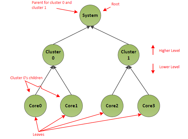
Fig. 8.6 Processor Hierarchy
The figure above depicts an example system, which comprises a system level processor container, which in turn contains two cluster processor containers, each of which contains two processors. The overall collection is called the processor hierarchy and standard tree terminology is used to refer to different parts of it. For example, an individual processor or container is called a node, the nodes which reside within a processor container are called children of that parent, etc. This example is symmetric but that is not a requirement. For example, a system may contain a different number of processors in different containers or an asymmetric hierarchy where one side of the topology tree is deeper than another. Also note that while this example includes a single top level processor container encompassing all processors, this is not a requirement. It is legal for a system to be described using a collection of trees. (See Note below)
Note
The processor hierarchy can be used to describe a number of different characteristics of system topology. The main example is shared power states, see the Low Power Idle states in Lower Power Idle States for details.
8.4.2.1. Processor Container Device
This optional device is a container object that acts much like a bus node in a namespace. It may contain child objects that are either processor devices or other processor containers. This allows representing hierarchical processor topologies. Each processor container or processor in the hierarchy is herein referred to as a node. The processor container device is declared using the hardware identifier (_HID) ACPI0010.
To aid support of operating systems which do not parse processor containers, a container can carry a Compatible ID (_CID) of PNP0A05, which represents a generic container device (see Device Class-Specific Objects)
A processor container declaration must supply a _UID method returning an ID that is unique in the processor container hierarchy. A processor container must contain either other processor containers or other processor devices declared within its scope. In addition, a processor container may also contain the following methods in its scope:
Object |
Description |
|---|---|
_LPI |
Declares local power states for the hierarchy node represented by the processor container |
_RDI |
Declares power resource dependencies that affect system level power states |
_STA |
Determines the status of a processor container. See Device Class-Specific Objects. |
_LPI may be present under a processor device, and is described in _LPI (Low Power Idle States). RDI can only be present under a singular top level processor container object, and is described below.
ACPI allows the definition of more than one root level processor container. In other words, it is possible to define multiple top level containers. For example, in a NUMA system if there are no idle states or other objects that need to be encapsulated at the system level, multiple NUMA-node level processor containers may be defined at the top level of the hierarchy.
Processor Container Device objects are only valid for implementations conforming to ACPI 6.0 or higher. A platform can ascertain whether an operating system supports parsing of processor container objects via the _OSC method (see Platform-Wide OSPM Capabilities).
8.4.3. Lower Power Idle States
ACPI 6.0 introduces Lower Power Idle states (LPI). This extends the specification to allow expression of idle states that, like C-states, are selected by the OSPM when a processor goes idle, but which may affect more than one processor, and may affect other system components. LPI extensions in the specification leverage the processor container device, and in this way can express which parts of the system are affected by a given LPI state.
LPI states are defined via the following objects:
_LPI objects define the states themselves, and may be declared inside a processor or a processor container device
_RDI allows expressing constraints on LPI usage borne out of device usage
8.4.3.1. Hierarchical Idle States
Processor containers (Processor Container Device) can be used in conjunction with _LPI (_LPI (Low Power Idle States)) to describe idle states in a hierarchical manner. Within the processor hierarchy, each node has low power states that are specific to that node. ACPI refers to states that are specific to a node in the hierarchy as Local Power States. For example in the system depicted in Power states for processor hierarchy, the local power states of CPU0 are clock gate, retention and power down.
When the OS running on a given processor detects there is no more work to schedule on that processor, it needs to select an idle state. The state may affect more than just that processor. A processor going idle could be the last one in the system, or in a processor container, and therefore may select a power state what affects multiple processors. In order to select such a state, the OS needs to choose a local power state for each affected level in the processor hierarchy.
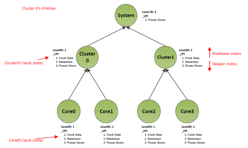
Fig. 8.7 Power states for processor hierarchy
Consider a situation where Core 0 is the last active core depicted in the example system, Power states for processor hierarchy. It may put the system into the lowest possible idle state. To do so, the OS chooses local state 3 (Power Down) for Core0, local state 3 (Power Down) for Cluster0, and local state 1 (Power Down) for the system. However, most HW architectures only support a single power state request from the OS to the platform. That is, it is not possible to make a separate local power state request per hierarchy node to the platform. Therefore, the OS must combine the per level local power states into a single Composite power state. The platform then acts on the Composite power state request.
A platform can only support a limited set of Composite power states, and not every combination of Local Power states across levels is valid. The valid power states in our example system are depicted in the following table.
System Level Processor Container |
Cluster level Processor Container |
Processor |
|---|---|---|
Running |
Running |
Clock Gated |
Running |
Running |
Retention |
Running |
Running |
Power Down |
Running |
Clock Gated |
Clock Gated |
Running |
Clock Gated |
Retention |
Running |
Clock Gated |
Power Down |
Running |
Retention |
Retention |
Running |
Retention |
Power Down |
Running |
Power Down |
Power Down |
Power Down |
Power Down |
Power Down |
8.4.3.2. Idle State Coordination
With hierarchical idle states, multiple processors affect the idle state for any non-leaf hierarchy node. Taking our example system in Power states for processor hierarchy, for cluster 0 to enter a low power state, both Core 0 and Core 1 must be idle. In addition, the power state selection done for Core 0 and Core 1 as they go idle has bearing on the state that can be used for Cluster 0. This requires coordination of idle state requests between the two processors. ACPI supports two different coordination schemes (detailed in subsections following):
Platform coordinated
OS initiated.
The OS and the platform can handshake on support for OS Initiated Idle or Platform Coordinated Idle using the _OSC method as described in Platform-Wide OSPM Capabilities. Note that an Architecture specific command may be required to enter OS Initiated mode, in which case please refer to architecture specific documentation. (For PSCI documentation see http://uefi.org/acpi under the heading “PCSI Specification”; for ARM FFH documentation, see http://uefi.org/acpi under the heading “ARM FFH Specification”.)
8.4.3.2.1. Platform Coordinated
With the Platform Coordinated scheme, the platform is responsible for coordination of idle states across processors. OSPM makes a request for all levels of hierarchy from each processor meaning that each processor makes a vote by requesting a local power state for itself, its parent, its parent’s parent, etc. (In some cases, the vote for a particular hierarchy level may be implicit - see the autopromotion discussion below for more details). When choosing idle states at higher levels, the OSPM on a processor may opt to keep a higher level node in a running state - this is still a vote for that node which the platform must respect. The vote expressed by the OSPM sets out the constraints on the local power state that the platform may choose for processor, and any parent nodes affected by the vote. In particular the vote expresses that the platform must not enter:
A deeper (lower power) local state than the requested one.
A local power state with a higher wake up latency than the requested one.
A local power state with power resource dependencies that the requested state does not have.
The platform looks across the votes for each hierarchy node from all underlying cores and chooses the deepest local state which satisfies all of the constraints associated with all of the votes. Normally, this just means taking the shallowest state that one of the cores voted for, since shallower states have lower wakeup latencies, lower minimum residencies, and fewer power resource dependencies. However, this may not always be the true, as state depth and latencies do not always increase together. For the sake of efficiency, the platform should generally not enter a power state with a higher minimum residency than the requested one. However, this is not a strict functional requirement. The platform may resolve to a state with higher minimum residency if it believes that is the most efficient choice based on the specific states and circumstances.
Using the above example in Power states for processor hierarchy, a simple flow would look like this:
Core0 goes idle - OS requests Core0 Power Down, Cluster0 Retention
Platform receives Core0 requests - place Core0 in the Power Down state
Core1 goes idle - OS requests Core1 Power Down, Cluster0 Power Down
Platform receives Core1 request - puts Core1 in the Power Down state, and takes shallowest vote for Cluster0, thus placing it into the Retention state
If the OSPM wanted to request power states beyond the cluster level, then Core0 and Core1 would both vote for an idle state at System level too, and the platform would resolve the final state selection across their votes and votes from any other processors under the System hierarchy via the method described above.
As mentioned above, certain platforms support a mechanism called autopromotion where the votes for higher level states may be implicit rather than explicit. In this scheme, the platform provides OSPM with commands to request idle states at a lower level of the processor hierarchy which automatically imply a specific idle state request at the respective higher level of the hierarchy. There is no command to explicitly request entry into the higher level state, only the implicit request based on the lower level state.
For example, if the platform illustrated in Power states for processor hierarchy uses autopromotion for the Cluster0 Clock Gated state, neither Core0 nor Core1 can explicitly request it. However, a core level Clock Gate request from either Core0 or Core1 would imply a Cluster0 Clock Gate request. Therefore, if both cores request core clock gating (or deeper), Cluster0 will be clock gated automatically by the platform. Additional details on how autopromotion is supported by ACPI can be found in Entry Method and Composition.
8.4.3.2.2. OS Initiated
In the OS Initiated coordination scheme, OSPM only requests an idle state for a particular hierarchy node when the last underlying processor goes to sleep. Obviously a processor always selects an idle state for itself, but idle states for higher level hierarchy nodes like clusters are only selected when the last processor in the cluster goes idle. The platform only considers the most recent request for a particular node when deciding on its idle state.
The main motivations for OS Initiated coordination are:
Avoid overhead of OSPM evaluating selection for higher level idle states which will not be used since other processors are still awake
Allow OSPM to make higher level idle state selections based on the latest information by taking only the most recent request for a particular node and ignoring requests from processors which went to sleep in the past (and may have been based on information which is now stale)
Using the above example in a simple flow would look like the following.
Step |
OS View of power states |
Platform view of power states |
|
|---|---|---|---|
0: |
Cores 0 and 1 are both awake and running code |
Core0: Running Core1: Running Cluster0: Running |
Core0: Running Core1: Running Cluster0: Running |
1 |
OS on Core0 requests Core0 PowerDown |
Core0: PowerDown Core1: Running Cluster0: Running |
Core0: Running Core1: Running Cluster0: Running |
2 |
Platform observes request and places Core0 into power down |
Core0: PowerDown Core1: Running Cluster0: Running |
Core0: PowerDown Core1: Running Cluster0: Running |
3 |
OS on Core1 requests Core1 PowerDown and Cluster0 PowerDown |
Core0: PowerDown Core1: PowerDown Cluster0: PowerDown |
Core0: PowerDown Core1: Running Cluster0: Running |
4 |
Platform observes requests for Core1 and Cluster0 and processes them |
Core0: PowerDown Core1: PowerDown Cluster0: PowerDown |
Core0: PowerDown Core1: PowerDown Cluster0: PowerDown |
Note that Core1 is making a cluster decision which affects both Core0 and Core1 so OSPM should consider expected sleep duration, wake up latency requirements, device dependencies, etc. for both cores and not just Core1 when requesting the cluster state.
The platform is still responsible for ensuring functional correctness. For example, if Core0 wakes back up, the cluster state requested by Core1 in the above example should be exited or the entry into the state should be aborted. OSPM has no responsibility to guarantee that the last core down is also the first core up, or that a core does not wake up just as another is requesting a higher level sleep state.
8.4.3.2.2.1. OS Initiated Request Semantics
With OS Initiated coordination, the ordering of requests from different cores is critically important since the platform acts upon the latest one. If the platform does not process requests in the order the OS intended then it may put the platform into the wrong state. Consider this scenario in our example system in Power states for processor hierarchy, as shown in the following table.
Step |
OS View of power states |
Platform view of power states |
|
|---|---|---|---|
0: |
Core0 in PowerDown, and Core1 is running |
Core0: PowerDown Core1: Running Cluster0: Running |
Core0: PowerDown Core1: Running Cluster0: Running |
1 |
Core1 goes idle – the OSPM requests Core1 PowerDown and Cluster0 Retention |
Core0: PowerDown Core1: PowerDown Cluster0: Retention |
Core0: PowerDown Core1: Running Cluster0: Running |
2 |
Core0 receives an interrupt and wakes up into platform |
Core0: PowerDown Core1: PowerDown Cluster0: Retention |
Core0: Running Core1: Running Cluster0: Running |
3 |
Core0 moves into OSPM and starts processing interrupt |
Core0: Running Core1: PowerDown Cluster0: Running |
Core0: Running Core1: Running Cluster0: Running |
4 |
Core0 goes idle and OSPM request Core0 Power Down, Cluster0 Power Down |
Core0: PowerDown Core1: PowerDown Cluster0: PowerDown |
Core0: Running Core1: Running Cluster0: Running |
5 |
Core0’s idle request “passes” Core1’s request. Platform puts Core0 to Power Down but ignores cluster request since Core1 is still running |
Core0: PowerDown Core1: PowerDown Cluster0: PowerDown |
Core0: PowerDown Core1: Running Cluster0: Running |
6 |
Core1’s request is observed by the platform. Platform puts Core1 to Power Down and Cluster0 to retention. |
Core0: PowerDown Core1: PowerDown Cluster0: PowerDown!! (See Note below) |
Core0: PowerDown Core1: PowerDown Cluster0: Retention!! (See Note below) |
Note
In the last row of the table above, the Cluster0 values are mismatched.
The key issue here is the race condition between the requests from the two cores; there is no guarantee that they reach the platform in the same order the OS made them. It is not expected to be common, but Core0’s request could “pass” Core1’s for a variety of potential reasons - lower frequency, different cache behavior, handling of some non-OS visible event, etc. This sequence of events results in the platform incorrectly acting on the stale Cluster0 request from Core1 rather than the latest request from Core0. The net result is that Cluster0 is left in the wrong state until the next wakeup.
To address such race conditions and ensure that the platform and OS have a consistent view of the request ordering, OS Initiated idle state request semantics are enhanced to include a hierarchical dependency check. When the platform receives a request, it is responsible for checking whether the requesting core is really the last core down in the requested domain and rejecting the request if not. Note that even if OSPM and the platform are behaving correctly, they may not always agree on the state of the system due to various races. For example, the platform may see a core waking up before OSPM, and therefore see that core as running, whilst the OSPM still sees it as sleeping. The platform can start treating a particular core as being in a low power state, for the sake of the dependency check, once it has seen the core’s request (so that it can be correctly ordered versus other OS requests). The platform must start treating a core as running before returning control to the OS after it wakes up from an idle state.
With this dependency check, the above example would change as follows:
Step: |
OS View of power states |
Platform view of power states |
|
|---|---|---|---|
0-4: |
Same as above |
Core0: PowerDown Core1: PowerDown Cluster0: PowerDown |
Core0: Running Core1: Running Cluster0: Running |
5 |
Core0’s idle request “passes” Core1’s request. Platform rejects Core0’s request since it includes Cluster0 but Core1 is still awake. |
Core0: PowerDown Core1: PowerDown Cluster0: PowerDown |
Core0: Running Core1: Running Cluster0: Running |
6 |
Core1’s request is observed by the platform. Platform rejects Core1’s request since it includes Cluster0 but Core0 is still awake. |
Core0: PowerDown Core1: PowerDown Cluster0: PowerDown |
Core0: Running Core1: Running Cluster0: Running |
7 |
OS resumes on Core0 |
Core0: Running Core1: PowerDown Cluster0: Running |
Core0: Running Core1: Running Cluster0: Running |
8 |
OS resumes on Core1 |
Core0: Running Core1: Running Cluster0: Running |
Core0: Running Core1: Running Cluster0: Running |
Once control is returned to the OS, it can handle as it sees fit - likely just re-evaluating the idle state on both cores. When requests are received out of order, some overhead is introduced by rejecting the command and forcing the OS to re-evaluate, but this is expected to be rare. Requests sent by the OS should be seen by the platform in the same order the vast majority of the time, and in this case, the idle command will proceed as normal.
It is possible that the OS may choose to keep a particular hierarchy node running even if all CPUs underneath it are asleep. This gives rise to another potential corner case - see below.
Step |
OS View of power states |
Platform view of power states |
|
|---|---|---|---|
0: |
Core0 in PowerDown, and Core1 is running |
Core0: PowerDown Core1: Running Cluster0: Running |
Core0: PowerDown Core1: Running Cluster0: Running |
1 |
Core1 goes idle – the OSPM OS requests Core1 PowerDown and Cluster0 Retention |
Core0: PowerDown Core1: PowerDown Cluster0: Retention |
Core0: PowerDown Core1: Running Cluster0: Running |
2 |
Core0 receives an interrupt and wakes up into platform |
Core0: PowerDown Core1: PowerDown Cluster0: Retention |
Core0: Running Core1: Running Cluster0: Running |
3 |
Core0 moves into OSPM and starts processing interrupt |
Core0: Running Core1: PowerDown Cluster0: Running |
Core0: Running Core1: Running Cluster0: Running |
4 |
Core0 goes idle and OSPM request Core0 Power Down and requests Cluster0 to stay running |
Core0: PowerDown Core1: PowerDown Cluster0: Running |
Core0: Running Core1: Running Cluster0: Running |
5 |
Core0’s idle request “passes” Core1’s request. Platform puts Core0 to PowerDown. Even though the OS made a request for the cluster to run, Platform does not know to reject Core0’s request since it doesn’t include a Cluster idle state |
Core0: PowerDown Core1: PowerDown Cluster0: Running |
Core0: PowerDown Core1: Running Cluster0: Running |
6 |
Core1’s request is observed by the platform. Platform puts Core1 to Power Down and Cluster0 to retention. |
Core0: PowerDown Core1: PowerDown Cluster0: Running!! (See Note, below) |
Core0: PowerDown Core1: PowerDown Cluster0: Retention!! (See Note below) |
Note
In the last row of the table above, the Cluster0 values are mismatched.
The fundamental issue is that the platform cannot infer what hierarchy level a request is for, based on what levels are being placed into a low power mode. To mitigate this, each idle state command must include a hierarchy parameter specifying the highest level hierarchy node for which the OS is making a request in addition to the normal idle state identifier. Even if the OS does not want some higher level hierarchy node to enter an idle state, it should indicate if the core is the last core down for that node. This allows the platform to understand the OS’s view of the state of the hierarchy and ensure ordering of requests even if the OS requests a particular node to stay running.
This enhancement is illustrated in the following table.
Step |
OS View of power states |
Platform view of power states |
|
|---|---|---|---|
0: |
Core0 in PowerDown, and Core1 is running |
Core0: PowerDown Core1: Running Cluster0: Running |
Core0: PowerDown Core1: Running Cluster0: Running |
1 |
Core1 goes idle – the OSPM OS requests Core1 PowerDown and Cluster0 Retention and identifies itself as last down in Cluster0 |
Core0: PowerDown Core1: PowerDown Cluster0: Retention |
Core0: PowerDown Core1: Running Cluster0: Running |
2 |
Core0 receives an interrupt and wakes up into platform |
Core0: PowerDown Core1: PowerDown Cluster0: Retention |
Core0: Running Core1: Running Cluster0: Running |
3 |
Core0 moves into OSPM and starts processing interrupt |
Core0: Running Core1: PowerDown Cluster0: Running |
Core0: Running Core1: Running Cluster0: Running |
4 |
Core0 goes idle and OSPM request Core0 Power Down and requests Cluster0 to stay running and identifies itself as last down in Cluster0 |
Core0: PowerDown Core1: PowerDown Cluster0: Running |
Core0: Running Core1: Running Cluster0: Running |
5 |
Core0’s idle request “passes” Core1’s request. Platform rejects Core0’s request since it is a request for Cluster0 but Core1 is still awake. |
Core0: PowerDown Core1: PowerDown Cluster0: PowerDown |
Core0: Running Core1: Running Cluster0: Running |
6 |
Core1’s request is observed by the platform. Platform rejects Core1’s request since it is a request for Cluster0 but Core0 is still awake. |
Core0: PowerDown Core1: PowerDown Cluster0: PowerDown |
Core0: Running Core1: Running Cluster0: Running |
7 |
OS resumes on Core0 |
Core0: Running Core1: PowerDown Cluster0: Running |
Core0: Running Core1: Running Cluster0: Running |
8 |
OS resumes on Core1 |
Core0: Running Core1: Running Cluster0: Running |
Core0: Running Core1: Running Cluster0: Running |
As before, once control is returned to the OS, it can handle as it sees fit - likely just re-requesting the idle state on both cores.
8.4.3.3. _LPI (Low Power Idle States)
_LPI is an optional object that provides a method to describe Low Power Idle states that defines the local power states for each node in a hierarchical processor topology. The OSPM uses the _LPI object to select a local power state for each level of processor hierarchy in the system. These local state selections are then used to produce a composite power state request that is presented to the platform by the OSPM.
This object may be used inside a Processor Container or a processor declaration. _LPI takes the following format:
Arguments:
None
Return Value:
A variable-length Package containing the local power states for the parent Processor or Processor Container device as described in the table below. _LPI evaluation returns the following format:
Package {
   Revision,            // Integer (WORD)
   LevelID,             // Integer (QWORD)
   Count,               // Integer (WORD)
   LPI[1],              // Package
   ...
   LPI[N]               // Package
   }
Element |
Object Type |
Description |
|---|---|---|
Revision |
Integer (WORD) |
The revision number of the _LPI object. Current revision is 0. |
LevelID |
Integer (QWORD) |
A platform defined number that identifies the level of hierarchy of the processor node to which the LPI states apply. This is used in composition of IDs for OS Initiated states described in Entry Method and Composition. In a platform that only supports platform coordinated mode, this field must be 0. |
Count |
Integer (WORD) |
The count of following LPI packages. |
LPI[1] |
Package |
A Package containing the definition of LPI state 1. |
LPI[N] |
Package |
A Package containing the definition of LPI state N. |
Each LPI sub-Package contains the elements described below:
Package() {
   Min Residency,                 // Integer (DWORD)
   Worst case wakeup latency,     // Integer (DWORD)
   Flags,                         // Integer (DWORD)
   Arch. Context Lost Flags,      // Integer (DWORD)
   Residency Counter Frequency,   // Integer (DWORD)
   Enabled Parent State,          // Integer (DWORD)
   Entry Method,                  // Buffer (ResourceDescriptor) or
                                  // Integer (QWORD)
   Residency Counter Register     // Buffer (ResourceDescriptor)
   Usage Counter Register         // Buffer (ResourceDescriptor)
   State Name                     // String (ASCIIZ)
   }
Element |
Object Type |
Description |
|---|---|---|
Min Residency |
Integer (DWORD) |
Minimum Residency - time in microseconds after which a state becomes more energy efficient than any shallower state. See Power, Minimum Residency, and Worst Case Wakeup Latency. |
Worst case wakeup latency |
Integer (DWORD) |
Worst case time in microseconds from a wake interrupt being asserted to the return to a running state of the owning hierarchy node (processor or processor container). See Power, Minimum Residency, and Worst Case Wakeup Latency. |
Flags |
Integer (DWORD) |
Valid flags are described in Flags for LPI states. |
Arch. Context Lost Flags |
Integer (DWORD) |
Architecture specific context loss flags. These flags may be used by a processor architecture to indicate processor context that may be lost by the power state and must be handled by OSPM. See Architecture Specific Context Loss Flags for more details. |
Residency Counter Frequency |
Integer (DWORD) |
Residency counter frequency in cycles-per-second (Hz). Value 0 indicates that counter runs at an architectural-specifi c frequency. Valid only if a Residency Counter Register is defined. |
Enabled Parent State |
Integer (DWORD) |
Every shallower power state in the parent is also enabled. 0 implies that no local idle states may be entered at the parent node. |
Entry Method |
Buffer or Integer (QWORD) |
This may contain a resource descriptor or an integer. A Resource Descriptor with a single Register() descriptor may be used to describe the register that must be read in order to enter the power state. Alternatively, an integer may be provided in which case the integer would be used in composing the final Register Value that must be used to enter this state. This composition process is described below in Entry Method and Composition. |
Residency Counter Register |
Buffer |
Optional residency counter register which provides the amount of time the owning hierarchy node has been in this local power state. The time is provided in a frequency denoted by the Residency counter frequency field (see above). The register is optional. If the platform does not support it, then the following NULL register descriptor should be used: ResourceTemplate() {Register {(SystemMemory, 0, 0, 0, 0)}} . |
Usage Counter Register |
Buffer |
Optional register that provides the number of times the owning hierarchy node has been in this local power state. If the platform does not support this register, then the following NULL register descriptor should be used:
ResourceTemplate() {Register {(SystemMemory, 0, 0, 0, 0)}}
|
State Name |
String (ASCIIZ) |
String containing a human-readable identifier of this LPI state. This element is optional and an empty string (a null character) should be used if this is not supported. |
Element |
Bits |
Description |
|---|---|---|
Enabled |
0 |
1 if the power state is enabled for use | 0 if the power state is disabled |
It is not required that all processors or processor containers include _LPI objects. However, if a processor container includes an _LPI object, then all children processors or processor containers must have _LPI objects.
The following sections describe the more complex properties of LPI in more detail, as well as rules governing wakeup for LPI states.
8.4.3.3.1. Disabling a State
When a local state is disabled by clearing the Enabled bit in the Flags field, any deeper states for that node are not renumbered. This allows other properties which rely on indexing into the state list for that node (Enabled Parent State for example) to not change.
Disabled states should not be requested by the OS and values returned by Residency/Usage Counter Registers are undefined.
8.4.3.3.2. Enabled Parent State
As mentioned above, LPI represent local states, which must be combined into a composite state. However not every combination is possible. Consider the example system described in Power states for processor hierarchy. In this system it would not be possible to simultaneously select clock gating as local state for Core0 and power down as local state for Cluster0. As Core0 is physically in Cluster0, power gating the cluster would imply power gating the core. The correct combinations of local states for this example system are described in Valid Local State Combinations in preceding example system. LPI states support enumeration of the correct combinations through the Enabled Parent State (EPS) property.
LPI States are 1-indexed. Much like C and S states, LPI0 is considered to be a running state. For a given LPI, the EPS is a 1-based index into the processor containers’ _LPI states. The index points at the deepest local power state of the parent processor that the given LPI state enables. Every shallower power state in the parent is also enabled. Taking the system described in Fig. 8.7, the states and EPS value for the states is described in Table 8.14 below.
Category / Bit Value |
State |
Enabled Parent State |
|---|---|---|
System Level ProcessorContainer LPI States |
||
0 |
Running |
N/A |
1 |
Power Down |
0 |
Cluster Level ProcessorContainer LPI States |
||
0 |
Running |
N/A |
1 |
Clock Gating |
0 – System must be running if cluster is clock gated |
2 |
Retention |
0 – System must be running if cluster is in retention |
3 |
Power Down |
1 – System may be in power down if cluster is in power down |
Core Level ProcessorContainer LPI States |
||
0 |
Running |
N/A |
1 |
Clock Gating |
1 – Cluster may be clock gated or running of core is clock gated |
2 |
Retention |
2 – Cluster may running, or clock gated, or in retention if core is in retention |
3 |
Power Down |
3 – All states at cluster level are supported if the core is powered down |
8.4.3.3.3. Power, Minimum Residency, and Worst Case Wakeup Latency
Power is not included in _LPI since relative power of different states (along with minimum residency to comprehend transition energy), and not absolute power, drive OSPM idle state decisions. To correctly convey relative power, local states in _LPI must be declared in power consumption order. That is, the local states for a particular hierarchy node must be listed from highest power (shallowest) to lowest power (deepest).
The worst case wakeup latency (WCWL) for a particular local state is the longest time from when a wake interrupt is asserted, to when the hierarchy node can return to execution. Generally, the WCWL will be the idle state’s exit latency plus some portion of its entry latency. How much of the entry flow is included depends on where (and if) the platform supports checking for pending wake events and aborting the idle state entry. For any given power state there will be a “point of no return” after which the entry into the power state cannot be reversed. This is illustrated in Worst case wake latency below. The WCWL must include the time period from the point of no return to the time at which a wake up interrupt can be handled.
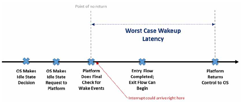
Fig. 8.8 Worst case wake latency
Note that other worst case paths could end up determining the WCWL, but what is described above is expected to be the most common. For example, there could be another period between the OS making the idle request and the point of no return where the platform does not check for wake up events, and which is longer than the time taken to enter and exit the power state. In that case that period would become the worst case wakeup latency.
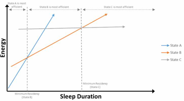
Fig. 8.9 Energy of states A,B and C versus sleep duration
Minimum residency (MR) is the time after which a state becomes more energy efficient than any shallower state. This parameter answers the fundamental question: how long does the hierarchy node need to stay in the idle state to overcome the energy cost of transitioning in/out, and make choosing that state a net win relative to shallower alternatives? Note that this also includes comparing against not entering an idle state and keeping the node running. This is illustrated in Energy of states A,B and C versus sleep duration, which shows the energy associated with three different state choices as a function of the sleep duration. Note that State A’s MR relative to keeping the node running is not pictured.
Generally, minimum residency and worst case wakeup latency will be larger for deeper states, however this may not always be the case. Taking a different example to the above, consider two system level states, StateY and StateZ, with similar entry overhead but where StateZ saves more power than StateY. An abstract state list might look like:
StateX: MR = 100 us
StateY: MR = 1000 us
StateZ: MR = 800 us, power resource A must be OFF
From an energy perspective, StateZ is always preferred, but in this example, StateZ is only available when certain device dependencies are met. This makes StateY attractive when the dependencies cannot be met. Despite being the deeper (lower power) state, StateZ has a lower MR than StateY since the entry overheads are similar and StateZ’s lower power more quickly amortizes the transition cost. Although the crossover, which sets MR, should generally be versus the next shallowest state, MR is defined relative to any shallower (higher power) state to deal with cases like this. In this case, StateZ’s MR is set by the crossover with StateX since StateZ (if allowed based on device dependencies) is always preferred to StateY. To achieve the lowest energy, OSPM must select the deepest (lowest power) state for which all entry constraints are satisfied and should not assume that deeper states are not viable just because a shallower state’s WCWL/MR threshold was not met.
Since WCWL may be used by OSPM to restrict idle state selection and guarantee response times to critical interrupts, it should be set conservatively (erring on the high side) so that OSPM is not surprised with worse than specified interrupt response time. On the other hand, MR helps OSPM make efficient decisions. If MR is inaccurate in a certain scenario and OSPM chooses a state which is deeper or shallower than optimal for a particular idle period, there may be some wasted energy but the system will not be functionally broken. This is not to say that MR doesn’t matter -energy efficiency is important - just that the platform may choose to optimize MR based on the typical case rather than the worst case.
8.4.3.3.3.1. Minimum Residency and Worst Case Wakeup Latency Combination Across Hierarchy Levels
The WCWL in _LPI is for a particular local state. When evaluating composite state choices versus system latency tolerance as part of idle state selection, OSPM will add wakeup latencies across hierarchy levels. For example, if a system has core powerdown with WCWL = 50 us and cluster powerdown with WCWL = 20 us then the core powerdown + cluster powerdown composite state latency is calculated as 70 us.
MRs defined in _LPI apply to a particular hierarchy node. The implicit assumption is that each hierarchy node represents an independent power manageable domain and can be considered separately. For example, assume that a cluster retention state is legal if the underlying cores are in core powerdown or core retention. The MR for cluster retention is based on the energy cost of taking shared logic outside of the cores in and out of retention versus the steady state power savings achieved in that shared logic while in that state. The key is that the specific state chosen at the core level does not fundamentally affect the cluster level decision since it is tied to properties of shared logic outside the core. The energy cost of entering/exiting the cluster state and the power savings it provides are independent of whether the core is in retention or powerdown. Based on this, MRs are considered independent per level in ACPI. That is, when comparing MR for different states to expected sleep duration for a particular node, OSPM uses the MRs defined in that node’s _LPI as is with no adjustment based on states at lower levels of hierarchy (though of course the state must be legal based on the lower level state’s Enabled Parent State property).
8.4.3.3.3.2. Known Limitations with Minimum Residency and Worst Case Wakeup Latency
Note that the WCWL and MR parameters are not perfect. For example, they do not scale with frequency, voltage, temperature, and various other factors which may affect them. Nor are the rules for how they combine across levels perfect. For example, cluster level MRs may move slightly based on core state choice since the entry latency of the core state will delay entry into the cluster state, derating the expected sleep duration. The cluster level MR can be adjusted to comprehend this, but if multiple core level states with different entry latencies enable the same cluster state, then its MR cannot perfectly comprehend them all. With that said, this set of parameters and combination scheme is believed to strike a good balance between simplicity/usability and accuracy.
8.4.3.3.4. Entry Method and Composition
The OSPM combines Local LPI states to create an overall composite power state. Each LPI state provides an entry method field. These fields, for the selected local power states, are combined to create the entry method register that must be read in order to enter a given composite power state.
To derive the appropriate register address from the local states’ entry methods, the following approach is used:
Local states for Processors always declare a register based entry method. This provides a base register.
Higher levels may use an integer or a register. If an Integer is used, then its value must be added to the base register obtained in step 1. If a register is used, then this becomes the new base register, overriding any previous value. Note that in this case, the selected LPI must imply specific local LPI selections for all lower level nodes.
In OS Initiated mode it is also necessary for the OSPM to tell the platform on which hierarchy level the calling processor is the last to go idle. This is done by adding the Level ID property of the hierarchy node’s LPI to the base register.
The basic composition algorithm for entry state is shown in the pseudo-code below for a platform coordinated system:
Reg = SelectedLocalState(CurrentProcessor).EntryMethod
WCWL = SelectedLocalState(CurrentProcessor).WCWL
MR = SelectedLocalState(CurrentProcessor).MR

for level = Parent(CurrentProcessor) to system
   LocalState = SelectedLocalState(level)
   If LocalState == Run
      break
   EM = LocalState.EntryMethod
   WCWL = WCWL+ LocalState.WCWL
   MR = LocalState.MR
   If IsInteger(EM)
      Reg.Addr = Reg.Addr+ZeroExtend(EM)
   Else
      // Entry method here overrides any previous method
      Reg = EM
CompositeState.EntryMethod = Reg
CompositeState.WCWL=WCWL
CompositeState.MR=MR
In OS Initiated mode it is also necessary for the OSPM to tell the platform on which hierarchy level the calling processor is the last to go idle and request a power state. To do this, the algorithm above is modified as follows:
Reg = SelectedLocalState(CurrentProcessor).EntryMethod
WCWL = SelectedLocalState(CurrentProcessor).WCWL
MR = SelectedLocalState(CurrentProcessor).MR

RegDecided = False
                      // Retrieve Level Index from Processor's \_LPI object
LastLevel = GetLevelIDOfLevel(CurrentProcessor)

for level = Parent(CurrentProcessor) to system
   LocalState = SelectedLocalState(level)

   If LocalState == Run
      break
   EM = LocalState.EntryMethod
   WCWL = WCWL+ LocalState.WCWL

      EM = LocalState.EntryMethod
      If IsInteger(EM)
         Reg.Addr = Reg.Addr+ZeroExtend(EM)
      Else
                      // Entry method is register
         Reg = EM

If IsProcessorLastInLevel(CurrentProcessor,level)
                      // If calling processor is last one to go idle in
                      // current level, retrieve Level Index from
                      // the container's \_LPI object
         LastLevel = GetLevelIDOfLevel(level)

Reg.Addr = Reg.Addr+LastLevel
CompositeState.EntryMethod = Reg
CompositeState.WCWL=WCWL
CompositeState.MR=MR
In a platform coordinated system, it is possible for an LPI belonging to a hierarchy node above the processor level to use an integer value of zero as its entry method. Since entry method composition is done by addition, this results in the entry command for that state being the same as for a composite state which only includes its children. An entry value of 0 essentially identifies a state as “autopromotable.” This means that the OS does not explicitly request entry into this state, but that the platform can automatically enter it when all children have entered states which allow the parent state based on their EPS properties. OSPM should follow normal composition procedure for other parameters (worst case wakeup latency, minimum residency, etc.) when including composite states involving autopromotable local states.
This is described in the following example:
Device (SYSM) {                   // System level states
   Name (_HID, "ACPI0010")
   Name (_UID, 0)
   Name (_LPI,
      Package() {
         0,                       // Version
         0,                       // Level ID
         1,                       // Count

         Package () {             // Power gating state for system
            900,                  // Min residency (uS)
            400,                  // Wake latency (uS)
            0,                    // Enabled Parent State
            ...                   // (skipped fields). . .
            ResourceTemplate () {
                                  // Register Entry method
               Register(FFH,0x20,0x00,0x00000000DECEA5ED,0x3)
            },
            ...                   // (skipped fields). . .
         }
      )

      Device (CLU0) {             // Package0 state
         Name (_HID, "ACPI0010")
         Name (_UID, 1)
         Name (_LPI,
            Package() {
               0,                 // Version
               0,                 // Level ID
               2,                 // Count
               Package () {       // Retention state for Cluster
                  40,             // Min residency (uS)
                  20,             // Wake latency (uS)
                  ...             // (skipped fields). . .
                  0,              // System must be running
                  0,              // Integer Entry method
                  ...             // (skipped fields). . .
                  },
               Package () {       // Power Gating state for Cluster
                  100,            // Min residency (uS)
                  80,             // Wake latency (uS)
                  ...             // (skipped fields). . .
                  1,              // System may power down
                  0x1020000,      // Integer Entry method
                  ...             // (skipped fields). . .
                  }
               }
            )
         Name(PLPI,
            Package() {
               0,                 // Version
               0,                 // Level ID
               2,                 // Count
               Package () {       // Retention state for CPU
                  40,             // Min residency (uS)
                  20,             // Wake latency (uS)
                  ...             // (skipped fields). . .
                  1,              // Parent node can be
                                  // in retention or running
                  ResourceTemplate () {
                                  // Register Entry method
                     Register(FFH,
                        0x20,0x00,
                        0x000000000000DEAF,0x3),
                     }
                  ...             // (skipped fields). . .
                  },
               Package () {       // Power Gating state for CPU
                  100,            // Min residency (uS)
                  80,             // Wake latency (uS)
                  ...             // (skipped fields). . .
                  2,              // Parent node can be in any state
                  ResourceTemplate () {
                                  // Register Entry method
                     Register(FFH,
                        0x20,0x00,
                        0x0000000000000DEAD,0x3),
                     }
                  ...             // (skipped fields). . .
                  }
               }
            )
         Device (CPU0) {          // Core0
               Name (_HID, "ACPI0007")
               Method (_LPI, 0, NotSerialized)
            {
                  return(PLPI)
            }
         }
         Device (CPU1) { // Core1
               Name (_HID, "ACPI0007")
               Method (_LPI, 0, NotSerialized)
            {
                  return(PLPI)
            }
         }
   }                              // end of NOD0
   Device (CLU1) {                // Package1 state
         Name (_HID, "ACPI0010")
         Name (_UID, 2)
      ....
   }
} // End of SYM
In the example above, the OSPM on CPU0 and CPU1 would be able to select the following composite states:
Core LPI |
Cluster LPI |
System LPI |
Composite State Entry Method |
|---|---|---|---|
Retention Register: 0xDEAF |
Run |
Run |
Core Retention Register: 0xDEAF |
Power Down Register 0xDEAD |
Run |
Run |
Core Power Down Register: 0xDEAD |
Retention Register: 0xDEAF |
Retention Integer: 0x0 |
Run |
Core Retain Retention Register 0xDEAF+0x0 = 0xDEAF |
Power Down Register: 0xDEAD |
Retention Integer: 0x0 |
Run |
Core Power Down Retention Register 0xDEAD+0x102000 0 = 0xDEAD |
Power Down Register: 0xDEAD |
Power Down Integer: 0x1020000 |
Run |
Core Power Down Power Down Register 0xDEAD+0x102000 0 = 0x102DEAD |
Power Down Register: 0xDEAD |
Power Down Integer: 0x1020000 |
Power Down Register : 0xDECEA5ED |
System Power Down Register 0xDECEA5ED |
As can be seen in the example, the cluster level retention state defines the integer value of 0 as its entry method. By virtue of composition, this means that the entry methods for the composite states Core Power Down and Core Power Down|Cluster Retention are the same (FFH register 0xDEAD). Similarly the composite states for Core Retention and Core Retention|Cluster Retention are the same (FFH register 0xDEAF). Consequently, if both CPU0 and CPU1 are in either Power Down or Power Retention, then the platform may enter cluster CLU0 into Retention.
The example also shows how a register based entry method at a high level overrides entry method definitions of lower levels. As pointed above this is only possible if the selected LPI implies specific LPIs at all lower levels. In this example the System Power Down LPI, entered through FFH register 0xDECEA5ED, implies Power Down LPIs at core and cluster level since based on EPS, no other core/cluster local states could enable System Power Down.
8.4.3.3.5. Architecture Specific Context Loss Flags
For Intel based systems the value of this flags register is 0.
For ARM based systems please refer to links to ACPI-Related Documents ( http://uefi.org/acpi ) under the heading “ARM FFH Specification”.
8.4.3.3.6. Residency and Entry Counter Registers
LPI state descriptions may optionally provide Residency and Usage Count registers to allow the OSPM to gather statistics about the platform usage of a given local state. Both registers provide running counts of their respective statistics. To measure a statistic over some time window, OSPM should sample at the beginning and end and calculate the delta. Whether the counters restart from 0 on various flavors of reset/S-state exit is implementation defined so OSPM should resynchronize its baseline on any reset or Sx exit.
The registers are optional, and if the feature is not present the platform must use a NULL register of the following form:
ResourceTemplate() {Register {(SystemMemory, 0, 0, 0, 0)}}
The Usage Count register counts how many times the local state has been used. Whether it counts entries or exits is implementation defined.
The Residency register counts how long the hierarchy node has been in the given LPI state, at a rate given by LPI’s Residency Counter Frequency field. A frequency of 0 indicates that the counter runs at an architecture-specific frequency. Whether the Residency counter runs continuously while in a local state or updates only on exit is implementation defined. If OSPM wants to guarantee that the reading for a particular state is current, it should read from that processor itself (or one of the underlying child processors in the case of a higher level idle state).
8.4.3.3.7. Wake from LPI States
With _LPI, the platform can describe deep S0-idle states which may turn off fundamental resources like bus clocks, interrupt controllers, etc. so special care must be taken to ensure that the platform can be woken from these states. This section describes handling for device initiated wakes. There are other wake sources such as timers, which are described elsewhere.
For device wakes, the requirement is that OSPM must not enter any LPI state that would prevent a device enabled for wake from waking the system. This means not entering any LPI state for which any Power Resource listed in _RDI (see the _RDI section _RDI (Resource Dependencies for Idle)) is required to be ON. Note that on a platform coordinated system, the OSPM may choose to enter an _LPI state even if there are resources listed in its companion RDI that are still on. However, if the OSPM has already enabled a device for wake, and ensured the power resources needed for wake are on, the platform will demote the LPI state to one where said resources remain on.
The wake device uses the standard _PRx and _PRW methods to describe power resources it requires to be ON based on its D-state and wake enabled status. This further implies that any device enabled for wake which depends on a resource which may be turned off as part of an LPI state must describe that dependency via _PRx/_PRW => _RDI => _LPI.
This is illustrated in the following example:
PowerResource(PWRA,0,0) {...}
PowerResource(PWRB,0,0) {...}
PowerResource(PWRC,0,0) {...}
PowerResource(PWRD,0,0) {...}
PowerResource(PWRE,0,1) {...}

Device (FOO) {
   Name(_S0W, 4) //Device in D3Cold can wake system from S0-idle
   Name(_PR0,Package(){PWRA, PWRB, PWRC})
   Name(_PR2,Package(){PWRA, PWRB})
   Name(_PR3,Package(){PWRA})
   Name(_PRE,Package(){PWRD})
   Name(_PRW,Package(){0, 0, PWRD} // PWRD must be ON for FOO to wake system
}

Device (BAR) {
   Name(_S0W, 3) // Device in D3Hot can wake system from S0-idle
   Name(_PR0,Package(){PWRA, PWRB})
   Name(_PR3,Package(){PWRC})
   Name(_PRW,Package(){PWRC}) // PWRC must be ON for BAR to wake system

}
Device (BAH) {
   Name(_S0W, 0) // This device can only wake the system from
                            // S0-idle if it is in D0
   Name(_PR0,Package(){PWRA, PWRB, PWRC})
}
Device (SYM) {
   Name(_RDI,
      Package() {
         0,                              // Version
         Package(){}                     // Local State 1 is Shallow;
                                         // Devices FOO, BAR and BAH can wake
                                         // the system if enabled for wake
         Package(){PWRA, PWRB}           // RDI for Local State 2. State is deeper
                                         // Device BAH cannot wake the system if this
                                         // state is used, as it needs PWRA and PWRB
                                         // to be able to wake the system
         Package(){PWRA, PWRB, PWRC}     // RDI for Local State 3.
                                         // Devices BAH and BAR cannot wake
                                         // the system, BAH needs PWRA, PWRB
                                         // and PWRC, and BAR needs PWRC
                                         // for all devices
      Package(){PWRA, PWRB, PWRC, PWRD}  // None of the devices listed
                                         // above could wake the system
      })
   ...
The example above declares a set of power resources (PWRA/B/C/D). Additionally, it has four system level local states that have the following dependencies:
LPI 1: Has no power resources dependencies
LPI 2: Requires PWRA and PWRB to be off
LPI 3: Requires PWRA, PWRB and PWRC to be off
LPI 4: Requires all of the power resources in the example to be off
Device BAH can only wake the system if it is in the D0 state. To be in D0 it requires PWRA, PWRB and PWRC to be on. Therefore device BAH could only wake the system from LPI 1. If this device is enabled for wake, then the platform must not enter LPI 2 or deeper.
Device BAR can wake the system in whilst it is in any device state other than D3Cold. However, to do so, it requires PWRC to be on. Therefore it can only wake the system from LPI 1 or LPI 2. If this device is enabled for wake, then the platform must not enter LPI 3 or deeper.
Device FOO can wake the system whilst it is in any device state. However to do so, it requires PWRD to be on. Therefore it can only wake the system from LPI 1 or LPI 2 or LPI 3. If this device is enabled for wake, then the platform must not enter LPI 4.
8.4.3.3.8. Default Idle State
The shallowest idle state for each leaf node in the hierarchy is the “default” idle state for that processor and is assumed to always be enterable. The worst case wakeup latency and minimum residency for this state must be low enough that OSPM need not consider them when deciding whether to use it. Aside from putting the processor in a power state, this state has no other software-visible effects. For example, it does not lose any context that OSPM must save/restore or have any device dependencies.
8.4.3.4. _RDI (Resource Dependencies for Idle)
Some platforms may have power resources that are shared between devices and processors. Abstractly, these resources are managed in two stages. First, the OS does normal power resource reference counting to detect when all device dependencies have been satisfied and the resource may be power managed from the device perspective. Then, when the processors also go idle, the OS requests entry into specific LPI states and the platform physically power manages the resources as part of the transition. The dependency between the power resources and the LPI state is described in _RDI.
_RDI objects may only be present at the root processor container that describes the processor hierarchy of the system. _RDI is not supported in a system that has more than one root node. _RDI is valid only in a singular top level container which encompasses all processors in the system.
The OSPM will ignore _RDI objects that are present at any node other than the root node. This simplification avoids complicated races between processors in one part of the hierarchy choosing idle states with resource dependencies while another processor is changing device states/power resources.
Arguments:
None
Return Value:
A variable-length Package containing the resource dependencies with the following format:
Return Value Information
Package {
   Revision,   // Integer (WORD)
   RDI[1],     // Package
   ...
   RDI[N]      // Package
}
Element |
Object Type |
Description |
Revision |
Integer (WORD) |
The revision number of the _RDI object. Current revision is 0. |
RDI[1] |
Package |
A variable length Package containing the power resource dependencies of system level power state 1. |
RDI[N] |
Package |
A variable length Package containing the power resource dependencies of system level power state N. |
Each RDI[x] sub-Package contains a variable number of References to power resources:
Package {
   Resource[0], // Object Reference to a Power Resource Object
   ...
   Resource[M] // Object Reference to a Power Resource Object
}
The Package contains as many RDI packages as there are system level power states in the root processor container node’s _LPI object. The indexing of LPI power states in this _LPI object matches the indexing of the RDI packages in the _RDI object. Thus the nth LPI state at the system level has resource dependencies listed in the nth RDI. Each RDI package returns a list of the power resource objects (passive or standard power resources) that must be in an OFF state to allow the platform to enter the LPI state. If a system level LPI does not have any resource dependencies, the corresponding RDI should be an empty Package.
Both traditional and passive power resources can be listed as dependencies in _RDI. For traditional power resources, OSPM should ensure that the resource is OFF before requesting a dependent LPI state. For passive power resources, there are no _ON/_OFF/_STA methods so the only requirement is to check that the reference count is 0 before requesting a dependent LPI state.
OSPM requirements for ordering between device/power resource transitions and power resource dependent LPI states differ based on the coordination scheme.
In a platform coordinated system the platform must guarantee correctness and demote the requested power state to one that will satisfy the resource and processor dependencies. OSPM may use the dependency info in _RDI as it sees fit, and may select a dependent LPI state even if resources remain ON.
In an OS initiated system, OSPM must guarantee that all power resources are off (or reference counts are 0, for passive power resources) before requesting a dependent LPI state.
_RDI Example
The following ASL describes a system that uses _RDI to describe the dependencies between three power resources and system level power states:
PowerResource(PWRA,0,0) {         // power rail local to DEVA
   Method(_ON) {...}              // active power resource (_OFF turns rail off)
   Method(_OFF) {...}
   Method(_STA) {...}
}

PowerResource(PWRB,0,0) {         // power rail shared between DEVB and the processor
   Method(_ON) {...}              // active power resource (_OFF drives platform vote)
   Method(_OFF) {...}
   Method(_STA) {...}
}

PowerResource(PWRC,0,0) {}        // clock rail shared between DEVC and the processor
                                  // passive power resource
Device (DEVA) {
   Name(_PR0,Package(){PWRA})
}

Device (DEVB) {
   Name(_PR0,Package(){PWRB})
}

Device (DEVC) {
   Name(_PR0,Package(){PWRC})
}

Device (SYM) {
   Name(_RDI,
      Package() {
         0,                          // Revision
         Package(){}                 // Local State 1 has no power resource
                                     // dependencies
         Package(){PWRA}             // Local State 2 cannot be entered if DEVA
                                     // is in D0 due to PWRA
         Package(){PWRA, PWRB, PWRC} // Local State 3 cannot be entered if
                                     // DEVA is in D0 (due to PWRA), DEVB is in
                                     // D0 (due to PWRB) or DEVC is in D0
                                     // (due to PWRC)
      })
   ...
OSPM will turn the traditional power resource (PWRA) ON or OFF by waiting for the reference count to reach 0 (meaning DEVA has left D0) and running the _OFF method. Similarly, PWRB is turned ON or OFF based on the state of DEVB. Note that because the CPUs require the shared power rail to be ON while they are running, PWRB’s _ON and _OFF drive a vote rather than the physical HW controls for the power rail. In this case, _STA reflects the status of the vote rather than the physical state of PWRB.
OSPM guarantees ordering between PWRA/PWRB’s _ON and _OFF transitions and DEVA/DEVB’s D-state transitions. That is, PWRA can only be turned OFF after DEVA has left D0, and must be turned ON before transitioning DEVA to D0. However, the OS requirements for ordering between power resource transitions and power resource dependent LPI states differ based on the coordination scheme.
In a platform coordinated system, OSPM may or may not track the power state of PWRA before selecting local state 2 or 3. The platform must independently guarantee that PWRA is OFF before entering local state 2 or 3, and must demote to a shallower state if OSPM selects local state 2 or 3 when PWRA is still on. Note that because OSPM is required to correctly sequence power resource transitions with device power transitions, the platform does not need to check the state of DEVA; it can rely on the state of PWRA to infer that DEVA is in an appropriate D-state.
Similarly, OSPM may or may not track the state of PWRB and PWRC before selecting local state 3, and the platform must independently guarantee that PWRB is off before entering either state. Because PWRC is a passive power resource, the platform does not know when the reference count on the power resource reaches 0 and instead must track DEVC’s state itself. Unless the platform has other mechanisms to track the state of DEVC, PWRC should be defined as a traditional power resource so that the platform can use its _ON and _OFF methods to guarantee correctness of operation.
In an OS initiated system, OSPM is required to guarantee that PWRA is OFF before selecting either local state 2 or 3. OSPM may meet this guarantee by waiting until it believes a processor is the last man down in the system, before checking the state of PWRA, and only selecting local state 2 or 3 in this case. If the processor was the last man down, then the request to enter local state 2 or 3 is legal and the platform can honor it. If another processor woke up in the meantime and turned PWRA on, then this becomes a race between processors which is addressed in the OS Initiated Request Semantics section (OS Initiated Request Semantics). Similarly, OSPM must guarantee PWRB is off and PWRC’s reference count is 0 before selecting local state 3.
In an OS initiated system, because OSPM guarantees that power resources are in their correct states before selecting system power states, the platform should use passive power resources unless there is additional runtime power savings to turning a power resource OFF. On a platform that only supports OS Initiated transitions, PWRB should be defined as a passive power resource because it is shared with processors and can only be turned off when the system power state is entered.
8.4.3.5. Compatibility
In order to support older operating systems which do not support the new idle management infrastructure, the _OSC method can be used to detect whether the OSPM supports parsing processor containers and objects associated with LPIs and (_LPI, _RDI). This is described in Rules for Evaluating _OSC.
A platform may choose to expose both _CST and _LPI for backward compatibility with operating systems which do not support _LPI. In this case, if OSPM supports _LPI, then it should be used in preference to _CST. At run time only one idle state methodology should be used across the entire processor hierarchy - _LPI or _CST, but not a mixture of both.
8.4.4. Processor Throttling Controls
ACPI defines two processor throttling (T state) control interfaces. These are:
The Processor Register Block’s (P_BLK’s) P_CNT register.
The combined _PTC, _TSS, and _TPC objects in the processor’s object list.
P_BLK based throttling state controls are described in ACPI Hardware Specification. Combined _PTC, _TSS, and _TPC based throttling state controls expand the functionality of the P_BLK based control allowing the number of T states to be dynamic and accommodate CPU architecture specific T state control mechanisms as indicated by registers defined using the Functional Fixed Hardware address space. While platform definition of the _PTC, _TSS, and _TPC objects is optional, all three objects must exist under a processor for OSPM to successfully perform processor throttling via these controls.
8.4.4.1. _PTC (Processor Throttling Control)
_PTC is an optional object that defines a processor throttling control interface alternative to the I/O address spaced-based P_BLK throttling control register (P_CNT) described in ACPI Hardware Specification
OSPM performs processor throttling control by writing the Control field value for the target throttling state (T-state), retrieved from the Throttling Supported States object (_TSS), to the Throttling Control Register (THROTTLE_CTRL) defined by the _PTC object. OSPM may select any processor throttling state indicated as available by the value returned by the _TPC control method.
Success or failure of the processor throttling state transition is determined by reading the Throttling Status Register (THROTTLE_STATUS) to determine the processor’s current throttling state. If the transition was successful, the value read from THROTTLE_STATUS will match the “Status” field in the _TSS entry that corresponds to the targeted processor throttling state.
Arguments:
None
Return Value:
A Package as described below
Return Value Information
Package
{
   ControlRegister    // Buffer (Resource Descriptor)
   StatusRegister     // Buffer (Resource Descriptor)
}
Element |
Object Type |
Description |
|---|---|---|
Control Register |
Buffer |
Contains a Resource Descriptor with a single Register() descriptor that describes the throttling control register. |
Status Register |
Buffer |
Contains a Resource Descriptor with a single Register() descriptor that describes the throttling status register. |
The platform must expose a _PTC object for either all or none of its processors. Notice that if the _PTC object exists, the specified register is used instead of the P_CNT register specified in the Processor term. Also notice that if the _PTC object exists and the _CST object does not exist, OSPM will use the processor control register from the _PTC object and the P_LVLx registers from the P_BLK.
Example
This is an example usage of the _PTC object in a Processor object list:
Processor (
      \_SB.CPU0,                    // Processor Name
      1,                            // ACPI Processor number
      0x120,                        // PBlk system IO address
      6 )                           // PBlkLen
 {                                  // Object List
   Name(_PTC, Package ()            // Processor Throttling Control object
      {
            ResourceTemplate(){Register(FFixedHW, 0, 0, 0)}, // Throttling_CTRL
           ResourceTemplate(){Register(FFixedHW, 0, 0, 0)} // Throttling_STATUS
      })                            // End of \_PTC object
}                                   // End of Object List
Example
This is an example usage of the _PTC object using the values defined in ACPI 1.0. This is an illustrative example to demonstrate the mechanism with well-known values.
Processor (
      \\_SB.CPU0,                 // Processor Name
      1,                          // ACPI Processor number
      0x120,                      // PBLK system IO address
      6 )                         // PBLK Len
    {                             // Object List
      Name(_PTC, Package ()       // Processor Throttling Control object -
           // 32 bit wide IO space-based register at the <p_blk> address
      {
         ResourceTemplate(){Register(SystemIO, 32, 0, 0x120)},  // Throttling_CTRL
        ResourceTemplate(){Register(SystemIO, 32, 0, 0x120)}    // Throttling_STATUS
      })                          // End of \_PTC object
   }                              // End of Object List
8.4.4.2. _TSS (Throttling Supported States)
This optional object indicates to OSPM the number of supported processor throttling states that a platform supports. This object evaluates to a packaged list of information about available throttling states including percentage of maximum internal CPU core frequency, maximum power dissipation, control register values needed to transition between throttling states, and status register values that allow OSPM to verify throttling state transition status after any OS-initiated transition change request. The list is sorted in descending order by power dissipation. As a result, the zeroth entry describes the highest performance throttling state (no throttling applied) and the ‘nth’ entry describes the lowest performance throttling state (maximum throttling applied).
When providing the _TSS, the platform must supply a _TSS entry whose Percent field value is 100. This provides a means for OSPM to disable throttling and achieve maximum performance.
Arguments:
None
Return Value:
A variable-length Package containing a list of Tstate sub-packages as described below.
Return Value Information
Package {
   TState [0] // Package - Throttling state 0
   ....
   TState [n] // Package - Throttling state n
}
Each Tstate sub-Package contains the elements described below.
Package {
   Percent    // Integer (DWORD)
   Power      // Integer (DWORD)
   Latency    // Integer (DWORD)
   Control    // Integer (DWORD)
   Status     // Integer (DWORD)
}
Element |
Object Type |
Description |
|---|---|---|
Percent |
Integer (DWORD) |
Indicates the percent of the core CPU operating frequency that will be available when this throttling state is invoked. The range for this field is 1-100. This percentage applies independent of the processor’s performance state (P-state). That is, this throttling state will invoke the percentage of maximum frequency indicated by this field as applied to the CoreFrequency field of the _PSS entry corresponding to the P-state for which the processor is currently resident. |
Power |
Integer (DWORD) |
Indicates the throttling state’s maximum power dissipation (in milliWatts). OSPM ignores this field on platforms the support P-states, which provide power dissipation information via the _PSS object. |
Latency |
Integer (DWORD) |
Indicates the worst-case latency in microseconds that the CPU is unavailable during a transition from any throttling state to this throttling state. |
Control |
Integer (DWORD) |
Indicates the value to be written to the Processor Control Register (THROTTLE_CTRL) in order to initiate a transition to this throttling state. |
Status |
Integer (DWORD) |
Indicates the value that OSPM will compare to a value read from the Throttle Status Register (THROTTLE_STATUS) to ensure that the transition to the throttling state was successful. OSPM may always place the CPU in the lowest power throttling state, but additional states are only available when indicated by the _TPC control method. A value of zero indicates the transition to the Throttling state is asynchronous, and as such no status value comparison is required. |
8.4.4.3. _TPC (Throttling Present Capabilities)
This optional object is a method that dynamically indicates to OSPM the number of throttling states currently supported by the platform. This method returns a number that indicates the _TSS entry number of the highest power throttling state that OSPM can use at a given time. OSPM may choose the corresponding state entry in the _TSS as indicated by the value returned by the _TPC method or any lower power (higher numbered) state entry in the _TSS.
Arguments:
None
Return Value:
An Integer containing the number of states supported:
0 - states 0 … nth state available (all states available)
1 - state 1 … nth state available
2 - state 2 … nth state available
…
n - state n available only
In order to support dynamic changes of _TPC object, Notify events on the processor object of type 0x82 will cause OSPM to reevaluate any _TPC object in the processor’s object list. This allows AML code to notify OSPM when the number of supported throttling states may have changed as a result of an asynchronous event. OSPM ignores _TPC Notify events on platforms that support P-states unless the platform has limited OSPM’s use of P-states to the lowest power P-state. OSPM may choose to disregard any platform conveyed T-state limits when the platform enables OSPM usage of other than the lowest power P-state.
8.4.4.4. _TSD (T-State Dependency)
This optional object provides T-state control cross logical processor dependency information to OSPM. The _TSD object evaluates to a packaged list containing a single entry that expresses the T-state control dependency among a set of logical processors.
Arguments:
None
Return Value:
A Package containing a single entry consisting of a T-state dependency Package as described below.
Return Value Information
Package {
   TStateDependency[0]    // Package
}

The TStateDependency sub-Package contains the elements described below:
Package {
   NumEntries             // Integer
   Revision               // Integer (BYTE)
   Domain                 // Integer (DWORD)
   CoordType              // Integer (DWORD)
   NumProcessors          // Integer (DWORD)
}
Element |
Object Type |
Description |
|---|---|---|
NumEntries |
Integer |
The number of entries in the TStateDependency package including this field. Current value is 5. |
Revision |
Integer (BYTE) |
The revision number of the TStateDependency package format. Current value is 0. |
Domain |
Integer (DWORD) |
The dependency domain number to which this T state entry belongs. |
CoordType |
Integer (DWORD) |
See Table 8.1 for supported T-state coordination types. |
Num Processors |
Integer (DWORD) |
The number of processors belonging to the domain for this logical processor’s T-states. OSPM will not start performing power state transitions to a particular T-state until this number of processors belonging to the same domain have been detected and started. |
Example
This is an example usage of the _TSD structure in a Processor structure in the namespace. The example represents a two processor configuration with three T-states per processor. For all T-states, there exists dependence between the two processors, such that one processor transitioning to a particular T-state, causes the other processor to transition to the same T-state. OSPM will be required to coordinate the T-state transitions between the two processors and can initiate a transition on either processor to cause both to transition to the common target T-state.
Processor (
   \_SB.CPU0,              // Processor Name
   1,                      // ACPI Processor number
   0x120,                  // PBlk system IO address
   6)                      // PBlkLen
{                          //Object List

   Name(_PTC, Package ()   // Processor Throttling Control object -
   // 32 bit wide IO space-based register at the <p_blk> address
   {
      ResourceTemplate(){Register(SystemIO, 32, 0, 0x120)},  //   Throttling_CTRL
      ResourceTemplate(){Register(SystemIO, 32, 0, 0x120)}   //   Throttling_STATUS
   })                      // End of \_PTC object

   Name (_TSS, Package()
   {
      Package() {
         0x64,              // Frequency Percentage (100%, Throttling OFF state)
         0x0,               // Power
         0x0,               // Transition Latency
         0x7,               // Control THT_EN:0 THTL_DTY:111
         0x0,               // Status
      }

      Package() {
         0x58,              // Frequency Percentage (87.5%)
         0x0,               // Power
         0x0,               // Transition Latency
         0xF,               // Control THT_EN:1 THTL_DTY:111
         0x0,               // Status
      }

      Package() {
         0x4B,             // Frequency Percentage (75%)
         0x0,              // Power
         0x0,              // Transition Latency
         0xE,              // Control THT_EN:1 THTL_DTY:110
         0x0,              // Status
      }
   })

   Name (_TSD, Package()
   {
      Package(){5, 0, 0, 0xFD, 2}    // 5 entries, Revision 0, Domain 0,
                                     // OSPM Coordinate, 2 Procs
   })                                // End of \_TSD object

   Method (_TPC, 0)        // Throttling Present Capabilities method
   {
      If (\_SB.AC)
      {
         Return(0)         // All Throttle States are available for use.
      }
      Else
      {
         Return(2)         // Throttle States 0 an 1 won't be used.
      }
   }                       // End of \_TPC method
}                          // End of processor object list

Processor (
   \_SB.CPU1,              // Processor Name
   2,                      // ACPI Processor number
   ,                       // PBlk system IO address
   )                       // PBlkLen
{ //Object List

   Name(_PTC, Package ()     // Processor Throttling Control object -
                             // 32 bit wide IO space-based register at the
                             // <p_blk> address
   {

   ResourceTemplate(){Register(SystemIO, 32, 0, 0x120)}, //   Throttling_CTRL
   ResourceTemplate(){Register(SystemIO, 32, 0, 0x120)}  //   Throttling_STATUS
   })                                                    // End of \_PTC object

   Name (_TSS, Package()
   {
      Package() {
         0x64,                // Frequency Percentage (100%, Throttling OFF state)
         0x0,                 // Power
         0x0,                 // Transition Latency
         0x7,                 // Control THT_EN:0 THTL_DTY:111
         0x0,                 // Status
      }

      Package() {
         0x58,                // Frequency Percentage (87.5%)
         0x0,                 // Power
         0x0,                 // Transition Latency
         0xF,                 // Control THT_EN:1 THTL_DTY:111
         0x0,                 // Status
      }\'

      Package() {
         0x4B,                // Frequency Percentage (75%)
         0x0,                 // Power
         0x0,                 // Transition Latency
         0xE,                 // Control THT_EN:1 THTL_DTY:110
         0x0,                 // Status
      }
   })

   Name (_TSD, Package()
   {
      Package(){5, 0, 0, 0xFD, 2}   // 5 entries, Revision 0, Domain 0,
                                    // OSPM Coordinate, 2 Procs
   }) // End of \_TSD object


   Method (_TPC, 0)           // Throttling Present Capabilities method
   {
      If (\_SB.AC)
      {
         Return(0)            // All Throttle States are available for use.
      }
      Else
      {
         Return(2)            // Throttle States 0 an 1 won't be used.
      }
   }                          // End of \_TPC method
}                             // End of processor object list
8.4.4.5. _TDL (T-state Depth Limit)
This optional object evaluates to the _TSS entry number of the lowest power throttling state that OSPM may use. _TDL enables the platform to limit the amount of performance reduction that OSPM may invoke using processor throttling controls in an attempt to alleviate an adverse thermal condition. OSPM may choose the corresponding state entry in the _TSS as indicated by the value returned by the _TDL object or a higher performance (lower numbered) state entry in the _TSS down to and including the _TSS entry number returned by the _TPC object or the first entry in the table (if _TPC is not implemented). The value returned by the _TDL object must be greater than or equal to the value returned by the _TPC object or the corresponding value to the last entry in the _TSS if _TPC is not implemented. In the event of a conflict between the values returned by the evaluation of the _TDL and _TPC objects, OSPM gives precedence to the _TPC object, limiting power consumption.
Arguments:
None
Return Value:
An Integer containing the Throttling Depth Limit _TSS entry number:
0 - throttling disabled.
1 - state 1 is the lowest power T-state available.
2 - state 2 is the lowest power T-state available.
…
n - state n is the lowest power T-state available.
In order for the platform to dynamically indicate the limit of performance reduction that is available for OSPM use, Notify events on the processor object of type 0x82 will cause OSPM to reevaluate any _TDL object in the processor’s object list. This allows AML code to notify OSPM when the number of supported throttling states may have changed as a result of an asynchronous event. OSPM ignores _TDL Notify events on platforms that support P-states unless the platform has limited OSPM’s use of P-states to the lowest power P-state. OSPM may choose to disregard any platform conveyed T-state depth limits when the platform enables OSPM usage of other than the lowest power P-state.
8.4.5. Processor Performance Control
Processor performance control is implemented through three optional objects whose presence indicates to OSPM that the platform and CPU are capable of supporting multiple performance states. The platform must supply all three objects if processor performance control is implemented. The platform must expose processor performance control objects for either all or none of its processors. The processor performance control objects define the supported processor performance states, allow the processor to be placed in a specific performance state, and report the number of performance states currently available on the system.
In a multiprocessing environment, all CPUs must support the same number of performance states and each processor performance state must have identical performance and power-consumption parameters. Performance objects must be present under each processor object in the system for OSPM to utilize this feature.
Processor performance control objects include the ‘_PCT’ package, ‘_PSS’ package, and the ‘_PPC’ method as detailed below.
8.4.5.1. _PCT (Performance Control)
This optional object declares an interface that allows OSPM to transition the processor into a performance state. OSPM performs processor performance transitions by writing the performance state-specific control value to a Performance Control Register (PERF_CTRL).
OSPM may select a processor performance state as indicated by the performance state value returned by the _PPC method, or any lower power (higher numbered) state. The control value to write is contained in the corresponding _PSS entry’s “Control” field.
Success or failure of the processor performance transition is determined by reading a Performance Status Register (PERF_STATUS) to determine the processor’s current performance state. If the transition was successful, the value read from PERF_STATUS will match the “Status” field in the _PSS entry that corresponds to the desired processor performance state.
Arguments:
None
Return Value:
A Package as described below
Return Value Information
Package
{
   ControlRegister        // Buffer (Resource Descriptor)
   StatusRegister         // Buffer (Resource Descriptor)
}
Element |
Object Type |
Description |
|---|---|---|
Control Register |
Buffer |
Contains a Resource Descriptor with a single Register() descriptor that describes the performance control register. |
Status Register |
Buffer |
Contains a Resource Descriptor with a single Register() descriptor that describes the performance status register. |
Example
Name (_PCT, Package()
{
   ResourceTemplate(){Perf_Ctrl_Register},    //Generic Register Descriptor
   ResourceTemplate(){Perf_Status_Register}   //Generic Register Descriptor
}) // End of \_PCT
8.4.5.2. _PSS (Performance Supported States)
This optional object indicates to OSPM the number of supported processor performance states that any given system can support. This object evaluates to a packaged list of information about available performance states including internal CPU core frequency, typical power dissipation, control register values needed to transition between performance states, and status register values that allow OSPM to verify performance transition status after any OS-initiated transition change request. The list is sorted in descending order by typical power dissipation. As a result, the zeroth entry describes the highest performance state and the ‘nth’ entry describes the lowest performance state.
Arguments:
None
Return Value:
A variable-length Package containing a list of Pstate sub-packages as described below
Return Value Information
Package {
   PState [0]             // Package - Performance state 0
   ....
   PState [n]             // Package - Performance state n
}
Each Pstate sub-Package contains the elements described below:
Package {
   CoreFrequency          // Integer (DWORD)
   Power                  // Integer (DWORD)
   Latency                // Integer (DWORD)
   BusMasterLatency       // Integer (DWORD)
   Control                // Integer (DWORD)
   Status                 // Integer (DWORD)
}
Element |
Object Type |
Description |
|---|---|---|
Core Frequency |
Integer (DWORD) |
Indicates the core CPU operating frequency (in MHz). |
Power |
Integer (DWORD) |
Indicates the performance state’s maximum power dissipation (in milliwatts). |
Latency |
Integer (DWORD) |
Indicates the worst-case latency in microseconds that the CPU is unavailable during a transition from any performance state to this performance state. |
Bus Master Latency |
Integer (DWORD) |
Indicates the worst-case latency in microseconds that Bus Masters are prevented from accessing memory during a transition from any performance state to this performance state. |
Control |
Integer (DWORD) |
Indicates the value to be written to the Performance Control Register (PERF_CTRL) in order to initiate a transition to the performance state. |
Status |
Integer (DWORD) |
Indicates the value that OSPM will compare to a value read from the Performance Status Register (PERF_STATUS) to ensure that the transition to the performance state was successful. OSPM may always place the CPU in the lowest power state, but additional states are only available when indicated by the _PPC method. |
8.4.5.3. _PPC (Performance Present Capabilities)
This optional object is a method that dynamically indicates to OSPM the number of performance states currently supported by the platform. This method returns a number that indicates the _PSS entry number of the highest performance state that OSPM can use at a given time. OSPM may choose the corresponding state entry in the _PSS as indicated by the value returned by the _PPC method or any lower power (higher numbered) state entry in the _PSS.
Arguments:
None
Return Value:
An Integer containing the range of states supported
0 - States 0 through nth state are available (all states available)
1 - States 1 through nth state are available
2 - States 2 through nth state are available
…
n - State n is available only
In order to support dynamic changes of _PPC object, Notify events on the processor object are allowed. Notify events of type 0x80 will cause OSPM to reevaluate any _PPC objects residing under the particular processor object notified. This allows AML code to notify OSPM when the number of supported states may have changed as a result of an asynchronous event (AC insertion/removal, docked, undocked, and so on).
8.4.5.3.1. OSPM _OST Evaluation
When processing of the _PPC object evaluation completes, OSPM evaluates the _OST object, if present under the Processor device, to convey _PPC evaluation status to the platform. _OST arguments specific to _PPC evaluation are described below.
Arguments: (2)
Arg0 - Source Event (Integer) : 0x80 Arg1 - Status Code (Integer) : see below
Return Value:
None
Argument Information:
Arg1 - Status Code 0: Success - OSPM is now using the performance states specified 1: Failure - OSPM has not changed the number of performance states in use.
8.4.5.4. Processor Performance Control Example
This is an example of processor performance control objects in a processor object list.
In this example, a uniprocessor platform that has processor performance capabilities with support for three performance states as follows:
500 MHz (8.2W) supported at any time
600 MHz (14.9W) supported only when AC powered
650 MHz (21.5W) supported only when docked
It takes no more than 500 microseconds to transition from one performance state to any other performance state.
During a performance transition, bus masters are unable to access memory for a maximum of 300 microseconds.
The PERF_CTRL and PERF_STATUS registers are implemented as Functional Fixed Hardware.
The following ASL objects are implemented within the system:
_SB.DOCK: Evaluates to 1 if system is docked, zero otherwise.
_SB.AC: Evaluates to 1 if AC is connected, zero otherwise.
Processor (
   \_SB.CPU0,                         // Processor Name
   1,                                 // ACPI Processor number
   0x120,                             // PBlk system IO address
   6 )                                // PBlkLen
{
   Name(_PCT, Package ()              // Performance Control object
   {
      ResourceTemplate(){Register(FFixedHW, 0, 0, 0)},         // PERF_CTRL
      ResourceTemplate(){Register(FFixedHW, 0, 0, 0)}          // PERF_STATUS
   })                                 // End of _PCT object

   Name (_PSS, Package()
   {
      Package(){650, 21500, 500, 300, 0x00, 0x08},   // Performance State zero (P0)
      Package(){600, 14900, 500, 300, 0x01, 0x05},   // Performance State one (P1)
      Package(){500, 8200, 500, 300, 0x02, 0x06}     // Performance State two (P2)
   })                                                // End of _PSS object

   Method (_PPC, 0)                   // Performance Present Capabilities method
   {
      If (\_SB.DOCK)
      {
         Return(0)                    // All _PSS states available (650, 600, 500).
      }
      If (\_SB.AC)
      {
         Return(1)                    // States 1 and 2 available (600, 500).
      }
      Else
      {
         Return(2)                    // State 2 available (500)
      }
   }                                  // End of _PPC method
}                                     // End of processor object list
The platform will issue a Notify(_SB.CPU0, 0x80) to inform OSPM to re-evaluate this object when the number of available processor performance states changes.
8.4.5.5. _PSD (P-State Dependency)
This optional object provides performance control, P-state or CPPC, logical processor dependency information to OSPM. The _PSD object evaluates to a packaged list containing a single entry that expresses the performance control dependency among a set of logical processors.
Arguments:
None
Return Value:
A Package with a single entry consisting of a P-state dependency Package as described below.
Return Value Information
Package {
   PStateDependency[0]    // Package
}
The PStateDependency sub-Package contains the elements described below:
Package {
   NumEntries             // Integer
   Revision               // Integer (BYTE)
   Domain                 // Integer (DWORD)
   CoordType              // Integer (DWORD)
   NumProcessors          // Integer (DWORD)
}
Element |
Object Type |
Description |
|---|---|---|
NumEntries |
Integer |
The number of entries in the PStateDependency package including this field. Current value is 5. |
Revision |
Integer (BYTE) |
The revision number of the PStateDependency package format. Current value is 0. |
Domain |
Integer (DWORD) |
The dependency domain number to which this P state entry belongs. |
CoordType |
Integer (DWORD) |
See Table 8.1 for supported P-state coordination types. |
Num Processors |
Integer (DWORD) |
The number of processors belonging to the domain for this logical processor’s P-states. OSPM will not start performing power state transitions to a particular P-state until this number of processors belonging to the same domain have been detected and started. |
Example
This is an example usage of the _PSD structure in a Processor structure in the namespace. The example represents a two processor configuration with three performance states per processor. For all performance states, there exists dependence between the two processors, such that one processor transitioning to a particular performance state, causes the other processor to transition to the same performance state. OSPM will be required to coordinate the P-state transitions between the two processors and can initiate a transition on either processor to cause both to transition to the common target P-state.
Processor (
   \_SB.CPU0,              // Processor Name
   1,                      // ACPI Processor number
   0x120,                  // PBlk system IO address
   6 )                     // PBlkLen
{
   Name(_PCT, Package ()   // Performance Control object
   {
      ResourceTemplate(){Register(FFixedHW, 0, 0, 0)},  // PERF_CTRL
      ResourceTemplate(){Register(FFixedHW, 0, 0, 0)}   // PERF_STATUS
   })                      // End of \_PCT object

   Name (_PSS, Package()
   {
      Package(){650, 21500, 500, 300, 0x00, 0x08},  // Performance State zero (P0)
      Package(){600, 14900, 500, 300, 0x01, 0x05},  // Performance State one (P1)
      Package(){500, 8200, 500, 300, 0x02, 0x06}    // Performance State two (P2)
   })                                               // End of \_PSS object

   Method (_PPC, 0)        // Performance Present Capabilities method
   {
   }                       // End of \_PPC method

    Name (_PSD, Package()
   {
      Package(){5, 0, 0, 0xFD, 2}     // 5 entries, Revision 0), Domain 0, OSPM
                                      // Coordinate, Initiate on any Proc, 2 Procs
   })                                 // End of \_PSD object
}                                     // End of processor object list

Processor (
   \_SB.CPU1,                         // Processor Name
   2,                                 // ACPI Processor number
   ,                                  // PBlk system IO address
   )                                  // PBlkLen
{
   Name(_PCT, Package ()              // Performance Control object
   {
      ResourceTemplate(){Register(FFixedHW, 0, 0, 0)},  // PERF_CTRL
      ResourceTemplate(){Register(FFixedHW, 0, 0, 0)}   // PERF_STATUS
   })                                                   // End of \_PCT object

   Name (_PSS, Package()
   {
      Package(){650, 21500, 500, 300, 0x00, 0x08},      // Performance State zero (P0)
      Package(){600, 14900, 500, 300, 0x01, 0x05},      // Performance State one (P1)
      Package(){500, 8200, 500, 300, 0x02, 0x06}        // Performance State two (P2)
   })                                                   // End of \_PSS object

   Method (_PPC, 0)                   // Performance Present Capabilities method
   {
   }                                  // End of \_PPC method

   Name (_PSD, Package()
   {
      Package(){5, 0, 0, 0xFD, 2}     // 5 entries, Revision 0, Domain 0, OSPM
                                      // Coordinate, Initiate on any Proc, 2 Procs
   })                                 // End of \_PSD object
}                                     // End of processor object list
8.4.5.6. _PDL (P-state Depth Limit)
This optional object evaluates to the _PSS entry number of the lowest performance P-state that OSPM may use when performing passive thermal control. OSPM may choose the corresponding state entry in the _PSS as indicated by the value returned by the _PDL object or a higher performance (lower numbered) state entry in the _PSS down to and including the _PSS entry number returned by the _PPC object or the first entry in the table (if _PPC is not implemented). The value returned by the _PDL object must be greater than or equal to the value returned by the _PPC object or the corresponding value to the last entry in the _PSS if _PPC is not implemented. In the event of a conflict between the values returned by the evaluation of the _PDL and _PPC objects, OSPM gives precedence to the _PPC object, limiting power consumption.
Arguments:
None
Return Value:
An Integer containing the P-state Depth Limit _PSS entry number:
0 - P0 is the only P-state available for OSPM use
1 - state 1 is the lowest power P-state available
2 - state 2 is the lowest power P-state available
…
n - state n is the lowest power P-state available
In order for the platform to dynamically indicate a change in the P-state depth limit, Notify events on the processor object of type 0x80 will cause OSPM to reevaluate any _PDL object in the processor’s object list. This allows AML code to notify OSPM when the number of supported performance states may have changed as a result of an asynchronous event.\
8.4.6. Collaborative Processor Performance Control
Collaborative processor performance control defines an abstracted and flexible mechanism for OSPM to collaborate with an entity in the platform to manage the performance of a logical processor. In this scheme, the platform entity is responsible for creating and maintaining a performance definition that backs a continuous, abstract, unit-less performance scale. During runtime, OSPM requests desired performance on this abstract scale and the platform entity is responsible for translating the OSPM performance requests into actual hardware performance states. The platform may also support the ability to autonomously select a performance level appropriate to the current workload. In this case, OSPM conveys information to the platform that guides the platform’s performance level selection.
Prior processor performance controls (P-states and T-states) have described their effect on processor performance in terms of processor frequency. While processor frequency is a rough approximation of the speed at which the processor completes work, workload performance isn’t guaranteed to scale with frequency. Therefore, rather than prescribe a specific metric for processor performance, Collaborative Processor Performance Control leaves the definition of the exact performance metric to the platform. The platform may choose to use a single metric such as processor frequency, or it may choose to blend multiple hardware metrics to create a synthetic measure of performance. In this way the platform is free to deliver the OSPM requested performance level without necessarily delivering a specific processor frequency. OSPM must make no assumption about the exact meaning of the performance values presented by the platform, or how they may correlate to specific hardware metrics like processor frequency.
Platforms must use the same performance scale for all processors in the system. On platforms with heterogeneous processors, the performance characteristics of all processors may not be identical. In this case, the platform must synthesize a performance scale that adjusts for differences in processors, such that any two processors running the same workload at the same performance level will complete in approximately the same time. The platform should expose different capabilities for different classes of processors, so as to accurately reflect the performance characteristics of each processor.
The control mechanisms are abstracted by the _CPC object method, which describes how to control and monitor processor performance in a generic manner. The register methods may be implemented in the Platform Communications Channel (PCC) interface (see Platform Communications Channel (PCC)). This provides sufficient flexibility that the entity OSPM communicates with may be the processor itself, the platform chipset, or a separate entity (e.g., a BMC).
In order to provide backward compatibility with existing tools that report processor performance as frequencies, the _CPC object can optionally provide processor frequency range values for use by the OS. If these frequency values are provided, the restrictions on _CPC information usage still remain: the OSPM must make no assumption about the exact meaning of the performance values presented by the platform, and all functional decisions and interaction with the platform still happen using the abstract performance scale. The frequency values are only contained in the _CPC object to allow the OS to present performance data in a simple frequency range, when frequency is not discoverable from the platform via another mechanism.
8.4.6.1. _CPC (Continuous Performance Control)
This optional object declares an interface that allows OSPM to transition the processor into a performance state based on a continuous range of allowable values. OSPM writes the desired performance value to the Desired Performance Register, and the platform maps the desired performance to an internal performance state.. If supported by the platform, OSPM may alternatively enable autonomous performance level selection while specifying minimum and maximum performance requirements.
Optional _CPC package fields that are not supported by the platform should be encoded as follows:
Integer fields: Integer 0
Register fields: the following NULL register descriptor should be used:
ResourceTemplate() {Register {(SystemMemory, 0, 0, 0, 0)}}
Arguments:
None
Return Value:
A Package containing the performance control information.
The performance control package contains the elements described below:
Package
{
   NumEntries,                              // Integer
   Revision,                                // Integer
   HighestPerformance,                      // Integer or Buffer (Resource Descriptor)
   NominalPerformance,                      // Integer or Buffer (Resource Descriptor)
   LowestNonlinearPerformance,              // Integer or Buffer (Resource Descriptor)
   LowestPerformance,                       // Integer or Buffer (Resource Descriptor)
   GuaranteedPerformanceRegister,           // Buffer (Resource Descriptor)
   DesiredPerformanceRegister ,             // Buffer (Resource Descriptor)
   MinimumPerformanceRegister ,             // Buffer (Resource Descriptor)
   MaximumPerformanceRegister ,             // Buffer (Resource Descriptor)
   PerformanceReductionToleranceRegister,   // Buffer (Resource Descriptor)
   TimeWindowRegister,                      // Buffer (Resource Descriptor)
   CounterWraparoundTime,                   // Integer or Buffer (Resource Descriptor)
   ReferencePerformanceCounterRegister,     // Buffer (Resource Descriptor)
   DeliveredPerformanceCounterRegister,     // Buffer (Resource Descriptor)
   PerformanceLimitedRegister,              // Buffer (Resource Descriptor)
   CPPCEnableRegister                       // Buffer (Resource Descriptor)
   AutonomousSelectionEnable,               // Integer or Buffer (Resource Descriptor)
   AutonomousActivityWindowRegister,        // Buffer (Resource Descriptor)
   EnergyPerformancePreferenceRegister,     // Buffer (Resource Descriptor)
   ReferencePerformance                     // Integer or Buffer (Resource Descriptor)
   LowestFrequency,                         // Integer or Buffer (Resource Descriptor)
   NominalFrequency                         // Integer or Buffer (Resource Descriptor)
}
Element |
Object Type |
Description |
|---|---|---|
NumEntries |
Integer |
The number of entries in the _CPC package, including this one. Current value is 23. |
Revision |
Integer (BYTE) |
The revision number of the _CPC package format. Current value is 3. |
Highest Performance |
Integer (DWORD) or Buffer |
Indicates the highest level of performance the processor is theoretically capable of achieving, given ideal operating conditions. If this element is an Integer, OSPM reads the integer value directly. If this element is a Buffer, it must contain a Resource Descriptor with a single Register() to read the value from. |
Nominal Performance |
Integer (DWORD) or Buffer |
Indicates the highest sustained performance level of the processor. If this element is an Integer, OSPM reads the integer value directly. If this element is a Buffer, it must contain a Resource Descriptor with a single Register() to read the value from. |
Lowest Nonlinear Performance |
Integer (DWORD) or Buffer |
Indicates the lowest performance level of the processor with non-linear power savings. If this element is an Integer, OSPM reads the integer value directly. If this element is a Buffer, it must contain a Resource Descriptor with a single Register() to read the value from. |
Lowest Performance |
Integer (DWORD) or Buffer |
Indicates the lowest performance level of the processor. If this element is an Integer, OSPM reads the integer value directly. If this element is a Buffer, it must contain a Resource Descriptor with a single Register() to read the value from. |
Guaranteed Performance Register |
Buffer |
Optional. If supported, contains a resource descriptor with a single Register() descriptor that describes the register to read the current guaranteed performance from. See the section “Performance Limiting” for more details. |
Desired Performance Register |
Buffer |
Contains a resource descriptor with a single Register() descriptor that describes the register to write the desired performance level. This register is optional when OSPM indicates support for CPPC2 in the platform-wide _OSC capabilities and the Autonomous Selection Enable register is Integer 1 |
Minimum Performance Register |
Buffer |
Optional. If supported, contains a resource descriptor with a single Register() descriptor that describes the register to write the minimum allowable performance level to. The value 0 is equivalent to Lowest Performance (no limit). |
Maximum Performance Register |
Buffer |
Optional. If supported, contains a resource descriptor with a single Register() descriptor that describes the register to write the maximum allowable performance level to. All 1s is equivalent to Highest Performance (no limit). |
Performance Reduction Tolerance Register |
Buffer |
Optional. If supported, contains a resource descriptor with a single Register() descriptor that describes the register to write the performance reduction tolerance. |
Time Window Register |
Buffer |
Optional. If supported, contains a resource descriptor with a single Register() descriptor that describes the register to write the nominal length of time (in ms) between successive reads of the platform’s delivered performance register. See the section “Time Window Register” for more details. |
Counter Wraparound Time |
Integer (DWORD) or Buffer |
Optional. If supported, indicates the minimum time to counter wraparound, in seconds. If this element is an Integer, OSPM reads the integer value directly. If this element is a Buffer (and supported), it must contain a Resource Descriptor with a single Register() to read the value from. |
Reference Performance Counter Register |
Buffer |
Contains a resource descriptor with a single Register() descriptor that describes the register to read a counter that accumulates at a rate proportional the reference performance of the processor. |
Delivered Performance Counter Register |
Buffer |
Contains a resource descriptor with a single Register() descriptor that describes the register to read a counter that accumulates at a rate proportional to the delivered performance of the processor. |
Performance Limited Register |
Buffer |
Contains a resource descriptor with a single Register() descriptor that describes the register to read to determine if performance was limited. A nonzero value indicates performance was limited. This register is sticky, and will remain set until reset or OSPM clears it by writing 0. See the section “Performance Limiting” for more details. |
CPPC EnableRegister |
Buffer |
Optional. If supported, contains a resource descriptor with a single Register() descriptor that describes a register to which OSPM writes a One to enable CPPC on this processor. Before this register is set, the processor will be controlled by legacy mechanisms (ACPI P-states, firmware, etc.). |
Autonomous Selection Enable |
Integer (DWORD) or Buffer |
Optional. If supported, contains a resource descriptor with a single Register() descriptor that describes a register to which OSPM writes a One to enable autonomous performance level selection. Platforms that exclusively support Autonomous Selection must populate this field as an Integer with a value of 1. |
AutonomousActivity-WindowRegister |
Buffer |
Optional. If supported, contains a resource descriptor with a single Register() descriptor that describes a register to which OSPM writes a time value that indicates a moving utilization sensitivity window for the autonomous selection policy. |
EnergyPerformance-PreferenceRegister |
Buffer |
Optional. If supported, contains a resource descriptor with a single Register() descriptor that describes a register to which OSPM writes a value to control the Energy vs. Performance preference of the platform’s energy efficiency and performance optimization policies when Autonomous Selection is enabled |
Reference Performance |
Integer (DWORD) or Buffer |
Optional. If supported, indicates the performance level at which the Reference Performance Counter accumulates. If not supported, The Reference Performance Counter accumulates at the Nominal performance level. If this element is an Integer, OSPM reads the integer value directly. If this element is a Buffer (and supported), it must contain a Resource Descriptor with a single Register() to read the value from |
Lowest Frequency |
Integer (DWORD) or Buffer |
Optional. If supported, indicates the lowest frequency for this processor in MHz. It should correspond roughly to the Lowest Performance value, but is not guaranteed to have any precise correlation. This value should only be used for the purpose of reporting processor performance in absolute frequency rather than on an abstract scale, and not for functional decisions or platform communication. If this element is an Integer, OSPM reads the integer value directly. If this element is a Buffer (and supported), it must contain a Resource Descriptor with a single Register() to read the value from. |
Nominal Frequency |
Integer (DWORD) or Buffer |
Optional. If supported, indicates the nominal frequency for this processor in MHz. It should correspond roughly to the Nominal Performance value, but is not guaranteed to have any precise correlation. This value should only be used for the purpose of reporting processor performance in absolute frequency rather than on an abstract scale, and not for functional decisions or platform communication. If this element is an Integer, OSPM reads the integer value directly. If this element is a Buffer (and supported), it must contain a Resource Descriptor with a single Register() to read the value from. |
The _CPC object provides OSPM with platform-specific performance capabilities / thresholds and control registers that OSPM uses to control the platform’s processor performance settings. These are described in the following sections. While the platform may specify register sizes within an allowable range, the size of the capabilities / thresholds registers must be compatible with the size of the control registers. If the platform supports CPPC, the _CPC object must exist under all processor objects. That is, OSPM is not expected to support mixed mode (CPPC & legacy PSS, _PCT, _PPC) operation.
Starting with ACPI Specification 6.2, all _CPC registers can be in PCC, System Memory, System IO, or Functional Fixed Hardware address spaces. OSPM support for this more flexible register space scheme is indicated by the “Flexible Address Space for CPPC Registers” _OSC bit.
8.4.6.1.1. Performance Capabilities / Thresholds
Performance-based controls operate on a continuous range of processor performance levels, not discrete processor states. As a result, platform capabilities and OSPM requests are specified in terms of performance thresholds. Platform performance thresholds outlines the static performance thresholds of the platform and the dynamic guaranteed performance threshold.
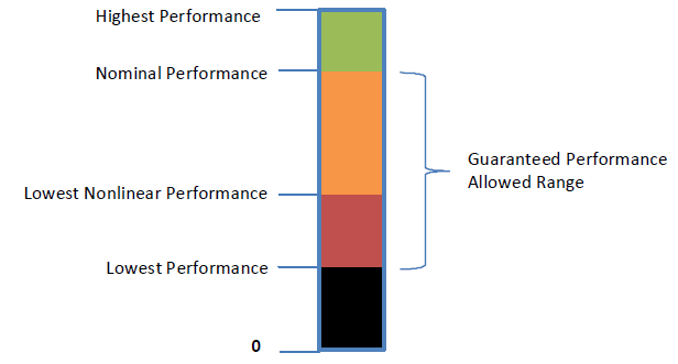
Fig. 8.10 Platform performance thresholds
Note
Not all performance levels need be unique. A platform’s nominal performance level may also be its highest performance level, for example.*
8.4.6.1.1.1. Highest Performance
Register or DWORD Attribute:  Read
Size:                         8-32 bits
Highest performance is the absolute maximum performance an individual processor may reach, assuming ideal conditions. This performance level may not be sustainable for long durations, and may only be achievable if other platform components are in a specific state; for example, it may require other processors be in an idle state.
Notify events of type 0x85 to the processor device object cause OSPM to re-evaluate the Highest Performance Register, but only when it is encoded as a buffer. Note: OSPM will not re-evaluate the _CPC object as a result of the notification.
8.4.6.1.1.2. Nominal Performance
Register or DWORD Attribute:  Read
Size:                         8-32 bits
Nominal Performance is the maximum sustained performance level of the processor, assuming ideal operating conditions. In absence of an external constraint (power, thermal, etc.) this is the performance level the platform is expected to be able to maintain continuously. All processors are expected to be able to sustain their nominal performance state simultaneously.
8.4.6.1.1.3. Reference Performance
Optional Register or DWORD Attribute:  Read
Size:                                  8-32 bits
If supported by the platform, Reference Performance is the rate at which the Reference Performance Counter increments. If not implemented (or zero), the Reference Performance Counter increments at a rate corresponding to the Nominal Performance level.
8.4.6.1.1.4. Lowest Nonlinear Performance
Register or DWORD Attribute:  Read
Size:                         8-32 bits
Lowest Nonlinear Performance is the lowest performance level at which nonlinear power savings are achieved, for example, due to the combined effects of voltage and frequency scaling. Above this threshold, lower performance levels should be generally more energy efficient than higher performance levels. In traditional terms, this represents the P-state range of performance levels.
This register effectively conveys the most efficient performance level to OSPM.
8.4.6.1.1.5. Lowest Performance
Register or DWORD Attribute:  Read
Size:                         8-32 bits
Lowest Performance is the absolute lowest performance level of the platform. Selecting a performance level lower than the lowest nonlinear performance level may actually cause an efficiency penalty, but should reduce the instantaneous power consumption of the processor. In traditional terms, this represents the T-state range of performance levels.
8.4.6.1.1.6. Guaranteed Performance Register
Optional Attribute:  Read
Size:                8-32 bits
Guaranteed Performance Register conveys to OSPM a Guaranteed Performance level, which is the current maximum sustained performance level of a processor, taking into account all known external constraints (power budgeting, thermal constraints, AC vs DC power source, etc.). All processors are expected to be able to sustain their guaranteed performance levels simultaneously. The guaranteed performance level is required to fall in the range [Lowest Performance, Nominal performance], inclusive.
If this register is not implemented, OSPM assumes guaranteed performance is always equal to nominal performance.
Notify events of type 0x83 to the processor device object will cause OSPM to re-evaluate the Guaranteed Performance Register. Changes to guaranteed performance should not be more frequent than once per second. If the platform is not able to guarantee a given performance level for a sustained period of time (greater than one second), it should guarantee a lower performance level and opportunistically enter the higher performance level as requested by OSPM and allowed by current operating conditions.
8.4.6.1.1.7. Lowest Frequency and Nominal Frequency
Optional Register or DWORD Attribute:  Read
Size:                                  32 bits
If supported by the platform, Lowest Frequency and Nominal Frequency values convey are the lowest and nominal CPU frequencies of the platform, respectively, in megahertz (MHz). They should correspond roughly to Lowest Performance and Nominal Performance on the CPPC abstract performance scale but precise correlation is not guaranteed. See Lowest Performance and Nominal Performance for more details.
These values should not be used for functional decision making or platform communication which are based on the CPPC abstract performance scale. They are only intended to enable CPPC platforms to be backwards compatible with OSs that report performance as CPU frequencies. The OS should use Lowest Frequency/Performance and Nominal Frequency/Performance as anchor points to create a linear mapping of CPPC abstract performance to CPU frequency, interpolating between Lowest and Nominal, and extrapolating from Nominal to Highest. Note that this mapping is not guaranteed to be accurate since CPPC abstract performance is not required to be based purely on CPU frequency, but it is better than no data if the OS must report performance as CPU frequency. Platforms should provide these values when they must work with OSs which need to report CPU frequency, and there is no alternate mechanism to discover this information.
8.4.6.1.2. Performance Controls
Under CPPC, OSPM has several performance settings it may use in conjunction to control/influence the performance of the platform. These control inputs are outlined in the following figure.
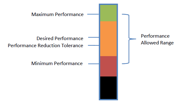
Fig. 8.11 OSPM performance controls
OSPM may select any performance value within the continuous range of values supported by the platform. Internally, the platform may implement a small number of discrete performance states and may not be capable of operating at the exact performance level desired by OSPM. If a platform-internal state does not exist that matches OSPM’s desired performance level, the platform should round desired performance as follows:
If OSPM has selected a desired performance level greater than or equal to guaranteed performance, the platform may round up or down. The result of rounding must not be less than guaranteed performance.
If OSPM has selected a desired performance level less than guaranteed performance and a maximum performance level not less than guaranteed performance, the platform must round up.
If OSPM has selected both desired performance level and maximum performance level less than guaranteed performance, the platform must round up if rounding up does not violate the maximum performance level. Otherwise, round down. OSPM must tolerate the platform rounding down if it chooses to set the maximum performance level less than guaranteed performance.This approach favors performance, except in the case where performance has been limited due to a platform or OSPM constraint.
When Autonomous Selection is enabled, OSPM limits the processor’s performance selection by writing appropriate constraining values to the Minimum and Maximum Performance registers. Setting Minimum and Maximum to the same value effectively disables Autonomous selection.
Note: When processors are within the same dependency domain, Maximum performance may only be actually limited when allowed by hardware coordination.
8.4.6.1.2.1. Maximum Performance Register
Optional Attribute:  Read/Write
Size:                8-32 bits
Maximum Performance Register conveys the maximum performance level at which the platform may run. Maximum performance may be set to any performance value in the range [Lowest Performance, Highest Performance], inclusive.
The value written to the Maximum Performance Register conveys a request to limit maximum performance for the purpose of energy efficiency or thermal control and the platform limits its performance accordingly as possible. However, the platform may exceed the requested limit in the event it is necessitated by internal package optimization. For Example, hardware coordination among multiple logical processors with interdependencies.
OSPM’s use of this register to limit performance for the purpose of thermal control must comprehend multiple logical processors with interdependencies. i.e. the same value must be written to all processors within a domain to achieve the desired result.
The platform must implement either both the Minimum Performance and Maximum Performance registers or neither register. If neither register is implemented and Autonomous Selection is disabled, the platform must always deliver the desired performance.
8.4.6.1.2.2. Minimum Performance Register
Optional Attribute:  Read/Write
Size:                8-32 bits
The Minimum Performance Register allows OSPM to convey the minimum performance level at which the platform may run. Minimum performance may be set to any performance value in the range [Lowest Performance, Highest Performance], inclusive but must be set to a value that is less than or equal to that specified by the Maximum Performance Register.
In the presence of a physical constraint, for example a thermal excursion, the platform may not be able to successfully maintain minimum performance in accordance with that set via the Minimum Performance Register. In this case, the platform issues a Notify event of type 0x84 to the processor device object and sets the Minimum_Excursion bit within the Performance Limited Register.
The platform must implement either both the Minimum Performance and Maximum Performance registers or neither register. If neither register is implemented and Autonomous Selection is disabled, the platform must always deliver the desired performance.
8.4.6.1.2.3. Desired Performance Register
Optional Attribute (depending on Autonomous Selection support):  Read/Write
Size:                                                            8-32 bits
When Autonomous Selection is disabled, the Desired Performance Register is required and conveys the performance level OSPM is requesting from the platform. Desired performance may be set to any performance value in the range [Minimum Performance, Maximum Performance], inclusive. Desired performance may take one of two meanings, depending on whether the desired performance is above or below the guaranteed performance level.
Below the guaranteed performance level, desired performance expresses the average performance level the platform must provide subject to the Performance Reduction Tolerance.
Above the guaranteed performance level, the platform must provide the guaranteed performance level. The platform should attempt to provide up to the desired performance level, if current operating conditions allow for it, but it is not required to do so
When Autonomous Selection is enabled, it is not necessary for OSPM to assess processor workload performance demand and convey a corresponding performance delivery request to the platform via the Desired Register. If the Desired Performance Register exists, OSPM may provide an explicit performance requirement hint to the platform by writing a non-zero value. In this case, the delivered performance is not bounded by the Performance Reduction Tolerance Register, however, OSPM can influence the delivered performance by writing appropriate values to the Energy Performance Preference Register. Writing a zero value to the Desired Performance Register or the non-existence of the Desired Performance Register causes the platform to autonomously select a performance level appropriate to the current workload.
Note
The Desired Performance Register is optional only when OPSM indicates support for CPPC2 in the platform-wide _OSC capabilities and the Autonomous Selection Enable field is encoded as an Integer with a value of 1.*
8.4.6.1.2.4. Performance Reduction Tolerance Register
Optional Attribute:  Read/Write
Size:                8-32 bits
The Performance Reduction Tolerance Register is used by OSPM to convey the deviation below the Desired Performance that is tolerable. It is expressed by OSPM as an absolute value on the performance scale. Performance Tolerance must be less than or equal to the Desired Performance. If the platform supports the Time Window Register, the Performance Reduction Tolerance conveys the minimal performance value that may be delivered on average over the Time Window. If this register is not implemented, the platform must assume Performance Reduction Tolerance = Desired Performance.
When Autonomous Selection is enabled, values written to the Performance Reduction Tolerance Register are ignored.
8.4.6.1.2.5. Time Window Register
Optional  Attribute:  Read/Write
Size:                 8-32 bits
Units:                milliseconds
When Autonomous Selection is not enabled, OSPM may write a value to the Time Window Register to indicate a time window over which the platform must provide the desired performance level (subject to the Performance Reduction Tolerance). OSPM sets the time window when electing a new desired performance The time window represents the minimum time duration for OSPM’s evaluation of the platform’s delivered performance (see Performance Counters “Performance Counters” for details on how OSPM computes delivered performance). If OSPM evaluates delivered performance over an interval smaller than the specified time window, it has no expectations of the performance delivered by the platform. For any evaluation interval equal to or greater than the time window, the platform must deliver the OSPM desired performance within the specified tolerance bound.
If OSPM specifies a time window of zero or if the platform does not support the time window register, the platform must deliver performance within the bounds of Performance Reduction Tolerance irrespective of the duration of the evaluation interval.
When Autonomous Selection is enabled, values written to the Time Window Register are ignored. Reads of the Time Window register indicate minimum length of time (in ms) between successive reads of the platform’s performance counters. If the Time Window register is not supported then there is no minimum time requirement between successive reads of the platform’s performance counters.
8.4.6.1.3. Performance Feedback
The platform provides performance feedback via set of performance counters, and a performance limited indicator.
8.4.6.1.3.1. Performance Counters
To determine the actual performance level delivered over time, OSPM may read a set of performance counters from the Reference Performance Counter Register and the Delivered Performance Counter Register.
OSPM calculates the delivered performance over a given time period by taking a beginning and ending snapshot of both the reference and delivered performance counters, and calculating:
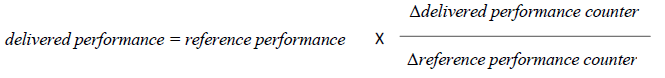
The delivered performance should always fall in the range [Lowest Performance, Highest Performance], inclusive. OSPM may use the delivered performance counters as a feedback mechanism to refine the desired performance state it selects.
When Autonomous Selection is not enabled, there are constraints that govern how and when the performance delivered by the platform may deviate from the OSPM Desired Performance. Corresponding to OSPM setting a Desired Performance: at any time after that, the following constraints on delivered performance apply
Delivered performance can be higher than the OSPM requested desired performance if the platform is able to deliver the higher performance at same or lower energy than if it were delivering the desired performance.
Delivered performance may be higher or lower than the OSPM desired performance if the platform has discrete performance states and needed to round down performance to the nearest supported performance level in accordance to the algorithm prescribed in the OSPM controls section.
Delivered performance may be lower than the OSPM desired performance if the platform’s efficiency optimizations caused the delivered performance to be less than desired performance. However, the delivered performance should never be lower than the OSPM specified Performance Reduction Tolerance. The Performance Reduction Tolerance provides a bound to the platform on how aggressive it can be when optimizing performance delivery. The platform should not perform any optimization that would cause delivered performance to be lower than the OSPM specified Performance Reduction Tolerance.
Reference Performance Counter Register
Attribute:  Read
Size:       32 or 64 bits
The Reference Performance Counter Register counts at a fixed rate any time the processor is active. It is not affected by changes to Desired Performance, processor throttling, etc. If Reference Performance is supported, the Reference Performance Counter accumulates at a rate corresponding to the Reference Performance level. Otherwise, the Reference Performance Counter accumulates at the Nominal performance level.
Delivered Performance Counter Register:
Attribute:  Read
Size:       32 or 64 bits
The Delivered Performance Counter Register increments any time the processor is active, at a rate proportional to the current performance level, taking into account changes to Desired Performance. When the processor is operating at its reference performance level, the delivered performance counter must increment at the same rate as the reference performance counter.
Counter Wraparound Time:
Optional Register or DWORD Attribute:  Read
Size:                                  32 or 64 bits
Units:                                 seconds
Counter Wraparound Time provides a means for the platform to specify a rollover time for the Reference/Delivered performance counters. If greater than this time period elapses between OSPM querying the feedback counters, the counters may wrap without OSPM being able to detect that they have done so.
If not implemented (or zero), the performance counters are assumed to never wrap during the lifetime of the platform.
8.4.6.1.3.2. Performance Limited Register
Attribute:  Read/Write
Size:       >=2 bit(s)
In the event that the platform constrains the delivered performance to less than the minimum performance or the desired performance (or, less than the guaranteed performance, if desired performance is greater than guaranteed performance) due to an unpredictable event, the platform sets the performance limited indicator to a non-zero value. This indicates to OSPM that an unpredictable event has limited processor performance, and the delivered performance may be less than desired / minimum performance. If the platform does not support signaling performance limited events, this register is permitted to always return zero when read.
Bit |
Name |
Description |
|---|---|---|
0 |
Desired_Excursion |
Set when Delivered Performance has been constrained to less than Desired Performance (or, less than the guaranteed performance, if desired performance is greater than guaranteed performance). This bit is not utilized when Autonomous Selection is enabled. |
1 |
Minimum_Excursion |
Set when Delivered Performance has been constrained to less than Minimum Performance |
2-n |
Reserved |
Reserved |
Bits within the Performance Limited Register are sticky, and will remain non-zero until OSPM clears the bit. The platform should only issue a Notify when Minimum Excursion transitions from 0 to 1 to avoid repeated events when there is sustained or recurring limiting but OSPM has not cleared the previous indication.
Note
All accesses to the Performance Limited Register must be made using interlocked operations, by both accessing entities.*
The performance limited register should only be used to report short term, unpredictable events (e.g., PROCHOT being asserted). If the platform is capable of identifying longer term, predictable events that limit processor performance, it should use the guaranteed performance register to notify OSPM of this limitation. Changes to guaranteed performance should not be more frequent than once per second. If the platform is not able to guarantee a given performance level for a sustained period of time (greater than one second), it should guarantee a lower performance level and opportunistically enter the higher performance level as requested by OSPM and allowed by current operating conditions.
8.4.6.1.4. CPPC Enable Register
Optional Attribute:  Read/Write
Size:                >=1 bit(s)
If supported by the platform, OSPM writes a one to this register to enable CPPC on this processor.
If not implemented, OSPM assumes the platform always has CPPC enabled.
8.4.6.1.5. Autonomous Selection Enable Register
Optional Register or DWORD Attribute:  Read/Write
Size:                                  >=1 bit(s)
If supported by the platform, OSPM writes a one to this register to enable Autonomous Performance Level Selection on this processor. CPPC must be enabled via the CPPC Enable Register to enable Autonomous Performance Level Selection. Platforms that exclusively support Autonomous Selection must populate this field as an Integer with a value of 1.
When Autonomous Selection is enabled, the platform is responsible for selecting performance states. OSPM is not required to assess processor workload performance demand and convey a corresponding performance delivery request to the platform via the Desired Performance Register.
8.4.6.1.6. Autonomous Activity Window Register
Optional Attribute:  Read/Write
Size:                10 bit(s)
Units:               Bits 06:00 - Significand,
                     Bits 09:07 - Exponent, Base_Time_Unit = 1E-6 seconds (1 microsecond)
If supported by the platform, OSPM may write a time value (10^3-bit exp * 7-bit mantissa in 1µsec units: 1us to 1270 sec) to this field to indicate a moving utilization sensitivity window to the platform’s autonomous selection policy. Combined with the Energy Performance Preference Register value, the Activity Window influences the rate of performance increase / decrease of the platform’s autonomous selection policy. OSPM writes a zero value to this register to enable the platform to determine an appropriate Activity Window depending on the workload.
Writes to this register only have meaning when Autonomous Selection is enabled.
8.4.6.1.7. Energy Performance Preference Register
Optional Attribute:  Read/Write
Size:                4-8 bit(s
If supported by the platform, OSPM may write a range of values from 0 (performance preference) to 0xFF (energy efficiency preference) that influences the rate of performance increase /decrease and the result of the hardware’s energy efficiency and performance optimization policies.This provides a means for OSPM to limit the energy efficiency impact of the platform’s performance-related optimizations / control policy and the performance impact of the platform’s energy efficiency-related optimizations / control policy.
Writes to this register only have meaning when Autonomous Selection is enabled.
8.4.6.1.8. OSPM Control Policy
8.4.6.1.8.1. In-Band Thermal Control
A processor using performance controls may be listed in a thermal zone’s _PSL list. If it is and the thermal zone engages passive cooling as a result of passing the _PSV threshold, OSPM will apply the \(\Delta P[\%]\) to modify the value in the desired performance register. Any time that passive cooling is engaged, OSPM must also set the maximum performance register equal to the desired performance register, to enforce the platform does not exceed the desired performance opportunistically.
Note: In System-on-Chip-based platforms where the SoC is comprised of multiple device components in addition to the processor, OSPM’s use of the Desired and Maximum registers for thermal control may not produce an optimal result because of SoC device interaction. The use of proprietary package level thermal controls (if they exist) may produce more optimal results.
8.4.6.1.9. Using PCC Registers
If the PCC register space is used, then all PCC registers for all processors in the same performance domain (as defined by _PSD), must be defined to be in the same subspace. If _PSD is not used, the restriction applies to all registers within a given _CPC object.
OSPM will write registers by filling in the register value and issuing a PCC write command. It may also read static registers, counters, and the performance limited register by issuing a read command (see Table 8.25).
To amortize the cost of PCC transactions, OSPM should read or write all PCC registers via a single read or write command when possible.
Command |
Description |
|---|---|
0x00 |
Read registers. Executed to request the platform update all registers for all enabled processors with their current value. |
0x01 |
Write registers. Executed to notify the platform one or more read/write registers for an enabled processor has been updated. |
0x02-0xFF |
All other values are reserved. |
8.4.6.1.10. Relationship to other ACPI-defined Objects and Notifications
If _CPC is present, its use supersedes the use of the following existing ACPI objects:
The P_BLK P_CNT register
_PTC
_TSS
_TPC
_TSD
_TDL
_PCT
_PSS
_PPC
_PDL
Notify 0x80 on the processor device
Notify 0x82 on the processor device
The _PSD object may be used to specify domain dependencies between processors. On a system with heterogeneous processors, all processors within a single domain must have the same performance capabilities.
8.4.6.1.11. _CPC Implementation Example
This example shows a two processor implementation of the _CPC interface via the PCC interface, in PCC subspace 2. This implementation uses registers to describe the processor’s capabilities, and does not support the Minimum Performance, Maximum Performance, or Time Window registers.
Processor (\_SB.CPU0, 1, 0, 0)
{
   Name(_CPC, Package()
   {
      21, // NumEntries
      2, // Revision
      ResourceTemplate(){Register(PCC, 32, 0, 0x120, 2)},
         // Highest Performance
      ResourceTemplate(){Register(PCC, 32, 0, 0x124, 2)},
         // Nominal Performance
      ResourceTemplate(){Register(PCC, 32, 0, 0x128, 2)},
         // Lowest Nonlinear Performance
      ResourceTemplate(){Register(PCC, 32, 0, 0x12C, 2)},
         // Lowest Performance
      ResourceTemplate(){Register(PCC, 32, 0, 0x130, 2)},
         // Guaranteed Performance Register
      ResourceTemplate(){Register(PCC, 32, 0, 0x110, 2)},
         // Desired Performance Register
      ResourceTemplate(){Register(SystemMemory, 0, 0, 0, 0)},
         // Minimum Performance Register
      ResourceTemplate(){Register(SystemMemory, 0, 0, 0, 0)},
         // Maximum Performance Register
      ResourceTemplate(){Register(SystemMemory, 0, 0, 0, 0)},
         // Performance Reduction Tolerance Register
      ResourceTemplate(){Register(SystemMemory, 0, 0, 0, 0)},
         // Time Window Register
      ResourceTemplate(){Register(PCC, 8, 0, 0x11B, 2)},
         // Counter Wraparound Time
      ResourceTemplate(){Register(PCC, 32, 0, 0x114, 2)},
         // Reference Performance Counter Register
      ResourceTemplate(){Register(PCC, 32, 0, 0x116, 2)},
         // Delivered Performance Counter Register
      ResourceTemplate(){Register(PCC, 8, 0, 0x11A, 2)},
         // Performance Limited Register
      ResourceTemplate(){Register(PCC, 1, 0, 0x100, 2)},
         // CPPC Enable Register
      ResourceTemplate(){Register(SystemMemory, 0, 0, 0, 0)},
         // Autonomous Selection Enable
      ResourceTemplate(){Register(SystemMemory, 0, 0, 0, 0)},
         // Autonomous Activity Window Register
      ResourceTemplate(){Register(SystemMemory, 0, 0, 0, 0)},
         // Energy Performance Preference Register
      ResourceTemplate(){Register(SystemMemory, 0, 0, 0, 0)}
         // Reference Performance
   })
}

Processor (\_SB.CPU1, 2, 0, 0)
{
   Name(_CPC, Package()
   {
      21, // NumEntries
      2, // Revision
      ResourceTemplate(){Register(PCC, 32, 0, 0x220, 2)},
         // Highest Performance
      ResourceTemplate(){Register(PCC, 32, 0, 0x224, 2)},
         // Nominal Performance
      ResourceTemplate(){Register(PCC, 32, 0, 0x228, 2)},
         // Lowest Nonlinear Performance
      ResourceTemplate(){Register(PCC, 32, 0, 0x22C, 2)},
         // Lowest Performance
      ResourceTemplate(){Register(PCC, 32, 0, 0x230, 2)},
         // Guaranteed Performance Register
      ResourceTemplate(){Register(PCC, 32, 0, 0x210, 2)},
         // Desired Performance Register
      ResourceTemplate(){Register(SystemMemory, 0, 0, 0, 0)},
         // Minimum Performance Register
      ResourceTemplate(){Register(SystemMemory, 0, 0, 0, 0)},
         // Maximum Performance Register
      ResourceTemplate(){Register(SystemMemory, 0, 0, 0, 0)},
         // Performance Reduction Tolerance Register
      ResourceTemplate(){Register(SystemMemory, 0, 0, 0, 0)},
         // Time Window Register
      ResourceTemplate(){Register(PCC, 8, 0, 0x21B, 2)},
         // Counter Wraparound Time
      ResourceTemplate(){Register(PCC, 32, 0, 0x214, 2)},
         // Reference Performance Counter Register
      ResourceTemplate(){Register(PCC, 32, 0, 0x216, 2)},
         // Delivered Performance Counter Register
      ResourceTemplate(){Register(PCC, 8, 0, 0x21A, 2)},
         // Performance Limited Register
      ResourceTemplate(){Register(PCC, 1, 0, 0x200, 2)},
         // CPPC Enable Register
      ResourceTemplate(){Register(SystemMemory, 0, 0, 0, 0)},
         // Autonomous Selection Enable
      ResourceTemplate(){Register(SystemMemory, 0, 0, 0, 0)},
         // Autonomous Activity Window Register
      ResourceTemplate(){Register(SystemMemory, 0, 0, 0, 0)},
         // Energy Performance Preference Register
      ResourceTemplate(){Register(SystemMemory, 0, 0, 0, 0)}
         // Reference Performance
   })
8.4.7. _PPE (Polling for Platform Errors)
This optional object, when present, is evaluated by OSPM to determine if the processor should be polled to retrieve corrected platform error information. This object augments /overrides information provided in the CPEP, if supplied. See Corrected Platform Error Polling Table (CPEP).
Arguments:
None
Return Value:
An Integer containing the recommended polling interval in milliseconds.
0 - OSPM should not poll this processor.
Other values - OSPM should poll this processor at <= the specified interval.
OSPM evaluates the _PPE object during processor object initialization and Bus Check notification processing.
8.5. Processor Aggregator Device
The following section describes the definition and operation of the optional Processor Aggregator device. The Processor Aggregator Device provides a control point that enables the platform to perform specific processor configuration and control that applies to all processors in the platform.
The Plug and Play ID of the Processor Aggregator Device is ACPI000C.
Object |
Description |
|---|---|
_PUR |
Requests a number of logical processors to be placed in an idle state |
8.5.1. Logical Processor Idling
In order to reduce the platform’s power consumption, the platform may direct OSPM to remove a logical processor from the operating system scheduler’s list of processors where non-processor affinitized work is dispatched. This capability is known as Logical Processor Idling and provides a means to reduce platform power consumption without undergoing processor ejection / insertion processing overhead. Interrupts directed to a logical processor and processor affinitized workloads will impede the effectiveness of logical processor idling in reducing power consumption as OSPM is not expected to re-target this work when a logical processor is idled.
8.5.1.1. _PUR (Processor Utilization Request)
The _PUR object is an optional object that may be declared under the Processor Aggregator Device and provides a means for the platform to indicate to OSPM the number of logical processors to be idled. OSPM evaluates the _PUR object as a result of the processing of a Notify event on the Processor Aggregator device object of type 0x80.
Arguments:
None
Return Value:
A Package as described below.
Return Value Information
Package
{

RevisionID // Integer: Current value is 1
NumProcessors // Integer

}
The NumProcessors package element conveys the number of logical processors that the platform wants OSPM to idle. This number is an absolute value. OSPM increments or decrements the number of logical processors placed in the idle state to equal the NumProcessors value as possible. A NumProcessors value of zero causes OSPM to place all logical processor in the active state as possible.
OSPM uses internal logical processor to physical core and package topology knowledge to idle logical processors successively in an order that maximizes power reduction benefit from idling requests. For example, all SMT threads constituting logical processors on a single processing core should be idled to allow the core to enter a low power state before idling SMT threads constituting logical processors on another core.
8.5.2. OSPM _OST Evaluation
When processing of the _PUR object evaluation completes, OSPM evaluates the _OST object, if present under the Processor Aggregator device, to convey _PUR evaluation status to the platform. _OST arguments specific to _PUR evaluation are described below.
Arguments: (3)
Arg0 - Source Event (Integer) : 0x80
Arg1 - Status Code (Integer) : see below
Arg2 - Idled Procs (Buffer) : see below
Return Value:
None
Argument Information:
Arg1 - Status Code:
0 -success - OSPM idled the number of logical processors indicated by the value of Arg2
1: no action was performed
Arg2 - A 4-byte buffer that represents a DWORD that is the number of logical processors that are now idled)
The platform may request a number of logical processors to be idled that exceeds the available number of logical processors that can be idled from an OSPM context for the following reasons:
The requested number is larger than the number of logical processors currently defined.
Not all the defined logical processors were onlined by the OS (for example. for licensing reasons)
Logical processors critical to OS function (for example, the BSP) cannot be idled.