7. Power and Performance Management
This section specifies the objects that support the device power management and system power management models described in ACPI Concepts. OSPM uses these objects to manage the platform by achieving a desirable balance between performance and energy conservation goals.
The system state indicator objects are also specified in this section.
7.1. Power Resource Objects and the Power Management Models
A Power Resource object refers to a software-controllable power plane, clock plane, or other resource upon which an ACPI power-managed device might rely. The unique way that these power resources are distributed to the devices across a given system sets the constraints within which OSPM must optimize the use of power, by individual devices as well as by the system as a whole. ACPI defines objects that reference power resources (or device states that, in turn, reference power resources) to enable OSPM to discover the constraints and capabilities of a given system. As power is managed during system operation, power savings are obtained by turning power resources off and on at the appropriate times. The following table describes how objects from this section provide the information and control required by OSPM to implement and coordinate the power management models.
Power mgmt function to be performed |
System entity performing it |
Platform info required |
Object providing information |
Comments |
|---|---|---|---|---|
Choose a supported device state to save power while device is idle |
Device Power Policy Owner |
List of states (D0 through D3hot, and D3cold) supported by the device |
_PRx, PSx |
D3cold support is indicated by explicitly providing _PR3. D3hot is assumed to be supported in all cases. |
Choose a supported device state to enable a targeted system sleep or Low-power Idle state |
Device Power Policy Owner |
List of states (D0 through D3hot, and D3cold) supported by the device in the targeted system sleep state |
_PRx, Power Resource Declaration, _SxD |
_PRx maps device states to Power Resources, Power Resource definition maps Power Resources to system states. _SxD provides the system state-to-device state mapping explicitly in case power resources do not produce the information (*see note below). |
Choose a device state that supports Wake |
Device Power Policy Owner |
List of supported states, filtered by ability to cause a wake event |
_PRW, _SxW |
Addition of the requirement for additional power resources listed in _PRW cause wake-incapable states to be removed from the list of supported states (above) SxW defines the mapping of wake capable device states to system states |
Arm a device for wake |
OSPM |
Control mechanisms for enabling wake at the platform level |
_PRW, Wake-capable device interrupt, _DSW |
_PRW specifies the GPE bit to enable for wake. On HW-reduced platforms, the wake-capable attribute of a device interrupt indicates which interrupt to enable for wake _DSW is optional, depending on the needs of the platform wake hardware |
Enter a selected device state |
OSPM |
Control mechanisms for power resources |
_ON, _OFF, _PSx |
_ON and _OFF control the power resources PSx controls other platform hardware relevant to state changes but not exposed to OSPM as power resources (*see note below). |
Choose a targeted system sleep state |
System Power Policy Owner |
List of supported system Sleep states (S1-S4) |
_Sx |
S0 and S5 are assumed to be supported in all cases |
Enter a selected system state |
OSPM |
Control mechanisms for system states |
_PTS, _TTS and _WAK |
If _S5 exists, ACPI uses the SLP_TYP/SLP_EN bit fields in the PM1 Control Register (or the SLEEP_CONTROL/ SLEEP_STATUS registers specified in the FADT). If _S5 is not specified, alternative methods are used to turn-off the system. |
Note
* Support for Low-power Idle states requires the use of power resources to describe the device state and wake dependencies. See Processor Aggregator Device and _LPI (Low Power Idle States).
7.2. Declaring a Power Resource Object
An ASL PowerResource statement is used to declare a PowerResource object. A Power Resource object refers to a software-controllable power plane, clock plane, or other resource upon which an integrated ACPI power-managed device might rely. Power resource objects can appear wherever is convenient in the namespace.
The syntax of a PowerResource statement is:
PowerResource (resourcename, systemlevel, resourceorder) {TermList}
where the systemlevel parameter is a number and the resourceorder parameter is a numeric constant (a WORD). For a formal definition of the PowerResource statement syntax, see Section 7.2.
Systemlevel is the deepest system sleep level OSPM must maintain to keep this power resource on (0 equates to S0, 1 equates to S1, and so on).
Each power-managed ACPI device lists the resources it requires for its supported power states. OSPM multiplexes this information from all devices and then enables and disables the required Power Resources accordingly. The resourceorder field in the Power Resource object is a value per Power Resource that provides the system with the order in which Power Resources must be enabled or disabled. Each unique resourceorder value represents a level, and any number of power resources may have the same level. Power Resource levels are enabled from low values to high values and are disabled from high values to low values. The operating software enables or disables all Power Resources in any one resourceorder level at a time before moving on to the next ordered level. Putting Power Resources in different order levels provides power sequencing and serialization where required. Note that no ordering is guaranteed within each level (i.e. between Power Resources with the same resourceorder value).
A Power Resource can have named objects under its Namespace location. For a description of the ACPI-defined named objects for a Power Resource, see Device Power Management Objects
The power management object list is encoded as TermList, so that rather than describing a static power management object list, it is possible to describe a dynamic power management object list according to the system settings. See “Definition Block Loading.
The following ASL code block example demonstrates the use of a PowerResource:
PowerResource(PIDE, 0, 0) {
    Method(_STA) {
        Return (Xor (GIO.IDEI, One, Zero))  // inverse of isolation
    }
    Method(_ON) {
        Store (One, GIO.IDEP)               // assert power
        Sleep (10)                          // wait 10ms
        Store (One, GIO.IDER)               // de-assert reset#
        Stall (10)                          // wait 10us
        Store (Zero, GIO.IDEI)              // de-assert isolation
    }
    Method(_OFF) {
        Store (One, GIO.IDEI)               // assert isolation
        Store (Zero, GIO.IDER)              // assert reset#
        Store (Zero, GIO.IDEP)              // de-assert power
    }
}
7.2.1. Defined Methods for a Power Resource
The Power Resource Methods table below lists the control methods that may be defined under a power resource. _ON, _OFF and _STA are required to allow basic control of each power resource. _RST is required in cases where reset of devices is managed through a shared power resource. As OSPM changes the state of device objects in the system, the power resources that are needed will also change, causing OSPM to turn power resources on and off. To determine the initial power resource settings the _STA method can be used. _RST is required in cases where reset of devices is controlled through a shared Power Resource (see _RST (Device Reset)).
Object |
Description |
|---|---|
_OFF |
Set the resource off. |
_ON |
Set the resource on. |
_RST |
Object that executes a platform level reset of all devices that list this resource in their _PRR object. (See _RST (Device Reset) for a description of this object.) |
_STA |
Object that evaluates to the current on or off state of the Power Resource. 0-OFF, 1-ON |
7.2.2. _OFF
This power resource control method puts the power resource into the OFF state. The control method must not complete until the power resource is off, including any required sequencing delays between, or after, operations on the power resource. OSPM is required to turn on or off only one resource at a time. The AML code can use Stall or Sleep within the method to cause the proper sequencing delays. OSPM is not required to run the _STA method to confirm that the resource has been successfully turned off, and may run the _OFF method repeatedly, even if the resource is already off.
Arguments:
None
Return Value:
None
7.2.3. _ON
This power resource control method puts the power resource into the ON state. The control method must not complete until the power resource is on, including any required sequencing delays between, or after, operations on the power resource. OSPM is required to turn on or off only one resource at a time. The AML code can use Stall or Sleep within the method to cause the proper sequencing delays. OSPM is not required to run the _STA method to confirm that the resource has been successfully turned on, and may run the _ON method repeatedly, even if the resource is already on.
Arguments:
None
Return Value:
None
7.2.4. _STA (Power Resource Status)
Returns the current ON or OFF status for the power resource.
Arguments:
None
Return Value:
An Integer containing the current power status of the device:
0 - The power resource is currently off
1 - The power resource is currently on
7.2.5. Passive Power Resources
In some platforms, certain power resources may be shared between devices and processors, requiring both to be in specific idle states before they can be turned off. Direct OSPM control of such resources is not possible while the OS is running because the processors depend on the resources being enabled whilst they are running. It is only when processors go idle that it may be possible to turn off these shared resources. For a given resource of this type this is only possible if, in addition to the processors being idle, any other devices that depend on the resource are in a state that allows powering it down. In these cases, the platform can manage the power resource as part of entry/exit from a Low Power Idle (LPI) state and OSPM can guide the decision on whether or not to turn off the resources with its LPI state request. In those cases the power resource _ON/_OFF/_STA methods are completely redundant.
Passive power resources, which are just like traditional power resources except they do not include _ON, _OFF, or _STA, are introduced to support this case. Omission of these methods reduces overhead by avoiding redundant evaluations and saves the platform from having to supply (working) methods which it does not need. Since OSPM cannot manage passive power resources directly via _ON/_OFF, passive power resources must be listed as a dependency of at least one LPI state where the platform will manipulate them. The dependencies between LPI states and power resources are described in the _RDI object. See _RDI (Resource Dependencies for Idle) for additional details.
7.3. Device Power Management Objects
For a device that is power-managed using ACPI, a Definition Block contains one or more of the objects found in the table below. Power management of a device is done using Power Resource control.
Power Resources are resources that could be shared amongst multiple devices. The operating software will automatically handle control of these devices by determining which particular Power Resources need to be in the ON state at any given time. This determination is made by considering the state of all devices connected to a Power Resource. At all times, OSPM ensures that any Power Resources no longer referenced by any device in the system is in the OFF state.
For systems that do not control device power states through power resource management (i.e. _PSx controls power transitions), but whose devices support multiple D-states, more information is required by the OS to determine the S-state to D-state mapping for the device. The ACPI firmware can give this information to OSPM by way of the _SxD methods. These methods tell OSPM for S-state “x”, the shallowest D-state supported by the device is “y.” OSPM is allowed to pick a deeper D-state for a given S-state, but OSPM is not allowed to go shallower than the given D-state.
Additional rules that apply to device power management objects are:
A device cannot be in a shallower D-state than its parent device.
If there exists an ACPI Object to set a device to D0 (either through _PSx or _PRx objects), then the corresponding object to set the device into a deeper Dx must also be declared, and vice versa.
If any ACPI Object that controls power (_PSx or _PRx, where x =0, 1, 2, or 3) exists, then methods to set the device into D0 and D3 device states (at least) must be present.
If a mixture of _PSx and _PRx methods is declared for the device, then the device states supported through _PSx methods must be identical to the device states supported through _PRx methods.
Note
For non-ACPI devices (bus-enumerated devices like USB or PCI), architectural bus definitions may have more stringent requirements.
When controlling power to devices which must wake the system during a system sleeping state:
The device must declare its ability to wake the system by declaring either the _PRW or _PSW object.
After OSPM has called _PTS, it must call the device’s _PSW to enable wake.
OSPM must transition a device into a D-state which is deeper than or equal to that specified by the device’s _SxD object (if present) to enable entry into Sx, but shallower than or equal to that specified by the device’s _SxW object so that it can still wake the system.
OSPM may transition the system to the specified sleep state.
Object |
Description |
|---|---|
_DSW |
Control method that enables or disables the device’s wake function for device-only wake. |
_PS0 |
Control method that puts the device in the D0 device state (device fully on). |
_PS1 |
Control method that puts the device in the D1 device state. |
_PS2 |
Control method that puts the device in the D2 device state. |
_PS3 |
Control method that puts the device in the D3 device state (device off). |
_PSC |
Object that evaluates to the device’s current power state. |
_PR0 |
Object that evaluates to the device’s power requirements in the D0 device state (device fully on). |
_PR1 |
Object that evaluates to the device’s power requirements in the D1 device state. The only devices that supply this level are those that can achieve the defined D1 device state according to the related device class. |
_PR2 |
Object that evaluates to the device’s power requirements in the D2 device state. The only devices that supply this level are those that can achieve the defined D2 device state according to the related device class. |
_PR3 |
Object that evaluates to the device’s power requirements in the D3hot device state. |
_PRW |
Object that evaluates to the device’s power requirements in order to wake the system from a system sleeping state. |
_PSW |
Control method that enables or disables the device’s wake function. |
_IRC |
Object that signifies the device has a significant inrush current draw. |
_S1D |
Shallowest D-state supported by the device in the S1 state |
_S2D |
Shallowest D-state supported by the device in the S2 state |
_S3D |
Shallowest D-state supported by the device in the S3 state |
_S4D |
Shallowest D-state supported by the device in the S4 state |
_S0W |
Deepest D-state supported by the device in the S0 state which can wake the device |
_S1W |
Deepest D-state supported by the device in the S1 state which can wake the system. |
_S2W |
Deepest D-state supported by the device in the S2 state which can wake the system. |
_S3W |
Deepest D-state supported by the device in the S3 state which can wake the system. |
_S4W |
Deepest D-state supported by the device in the S4 state which can wake the system. |
_RST |
Control method that executes a function level reset of the device. |
_PRR |
Object that evaluates to the device’s platform level reset requirements. |
_DSC |
Object that evaluates to the device’s deepest power state for configuration. |
7.3.1. _DSW (Device Sleep Wake)
In addition to _PRW, this control method can be used to enable or disable the device’s ability to wake a sleeping system. This control method can only access Operation Regions that are either always available while in a system working state or that are available when the Power Resources referenced by the _PRW object are all ON. For example, do not put a power plane control for a bus controller within configuration space located behind the bus. The method should enable the device only for the last system state/device state combination passed in by OSPM. OSPM will only pass in combinations allowed by the _SxD and _SxW objects.
The arguments provided to _DSW indicate the eventual Device State the device will be transitioned to and the eventual system state that the system will be transitioned to. The target system state is allowed to be the system working state (S0). The _DSW method will be run before the device is placed in the designated state and also before the system is placed in the designated system state.
Compatibility Note: The _PSW method was deprecated in ACPI 3.0. The _DSW method should be used instead. OSPM will only use the _PSW method if OSPM does not support _DSW or if the _DSW method is not present.
Arguments (3):
Arg0 - An Integer that contains the device wake capability control
0 - Disable the device’s wake capabilities
1 - Enable the device’s wake capabilities
Arg1 - An Integer that contains the target system state (0-4)
Arg2 - An Integer that contains the target device state
0 - The device will remain in state D0
1 - The device will be placed in either state D0 or D1
2 - The device will be placed in either state D0, D1, or D2
3 - The device will be placed in either state D0, D1, D2, or D3
Return Value:
None
7.3.2. _PS0 (Power State 0)
This Control Method is used to put the specific device into its D0 state. This Control Method can only access Operation Regions that are either always available while in a system working state or that are available when the Power Resources references by the _PR0 object are all ON.
Arguments:
None
Return Value:
None
7.3.3. _PS1 (Power State 1)
This control method is used to put the specific device into its D1 state. This control method can only access Operation Regions that are either always available while in the system working state (S0) or that are available when the Power Resources referenced by the _PR0 object are all ON.
Arguments:
None
Return Value:
None
7.3.4. _PS2 (Power State 2)
This control method is used to put the specific device into its D2 state. This control method can only access Operation Regions that are either always available while in the system working state (S0) or that are available when the Power Resources referenced by the _PR0 and _PR1 objects are all ON.
Arguments:
None
Return Value:
None
7.3.5. _PS3 (Power State 3)
This control method is used to put the specific device into its D3 state. This control method can only access Operation Regions that are either always available while in the system working state (S0) or that are available when the Power Resources referenced by the _PR0, _PR1 and PR2 objects are all ON.
Arguments:
None
Return Value:
None
7.3.6. _PSC (Power State Current)
This control method evaluates to the current device state. This control method is not required if the device state can be inferred by the Power Resource settings. This would be the case when the device does not require a _PS0, _PS1, _PS2, or _PS3 control method.
Arguments:
None
Return Value:
An Integer that contains a code for the current device state. The device state codes are shown in :the following table.
0 |
D0 |
|---|---|
1 |
D1 |
2 |
D2 |
3 |
D3 |
7.3.7. _PSE (Power State for Enumeration)
This control method is used to put a device into a powered mode appropriate for enumeration by its parent bus. This control method can only access Operation Regions that are either always available while in a system working state or that are available when the Power Resources referenced by the _PRE object are all ON.
Arguments:
Arg1 - An Integer indicating whether Enumeration power has been turned ON or will be turned OFF:
0 - OFF
1 - ON
Return Value:
None
7.3.8. _PR0 (Power Resources for D0)
This object evaluates to a list of power resources upon which this device is dependent when it is operating in the D0 state. For OSPM to put the device into the D0 device state, the following must occur in this order:
All Power Resources referenced by elements 1 through N must be in the ON state.
All Power Resources no longer referenced by any device in the system must be in the OFF state.
If present, the _PS0 control method is executed to set the device into the D0 device state.
Arguments:
None
Return Value:
A variable-length Package containing a list of References to power resources.
This object returns a package as defined below:
Element |
Object |
Description |
|---|---|---|
1 |
object reference |
Reference to required Power Resource #0 |
N |
object reference |
Reference to required Power Resource #N |
_PR0 must return the same data each time it is evaluated. All power resources referenced must exist in the namespace.
7.3.9. _PR1 (Power Resources for D1)
This object evaluates to a list of power resources upon which this device is dependent when it is in the D1 state. For OSPM to transition the device from the D0 state into the D1 state, the following must occur, in order:
If present, the _PS1 control method is executed to set the device into the D1 device state.
All Power Resources referenced by elements 1 through N must be in the ON state.
All Power Resources no longer referenced by any device in the system must be in the OFF state.
Arguments:
None
Return Value:
A variable-length Package containing a list of References to power resources.
This object evaluates to a package as defined in Power Resource Requirements Package.
_PR1 must return the same data each time it is evaluated. All power resources referenced must exist in the namespace.
7.3.10. _PR2 (Power Resources for D2)
This object evaluates to a list of power resources upon which this device is dependent when it is in the D2 state. For OSPM to transition the device into the D2 state, the following must occur, in order:
If present, the _PS2 control method is executed to set the device into the D2 device state.
All Power Resources referenced by elements 1 through N must be in the ON state.
All Power Resources no longer referenced by any device in the system must be in the OFF state.
Arguments:
None
Return Value:
A variable-length Package containing a list of References to power resources.
_PR2 must return the same data each time it is evaluated. All power resources referenced must exist in the namespace.
7.3.11. _PR3 (Power Resources for D3hot)
This object evaluates to a list of power resources upon which this device is dependent when it is in the D3hot state. For OSPM to transition the device into the D3hot state, the following must occur, in order:
If present, the _PS3 control method is executed to set the device into the D3hot device state.
All Power Resources referenced by elements 1 through N must be in the ON state.
All Power Resources no longer referenced by any device in the system must be in the OFF state.
Arguments:
None
Return Value:
A variable-length Package containing a list of References to power resources.
_PR3 must return the same data each time it is evaluated. All power resources referenced must exist in the namespace.
Interaction between _PR3 and entry to D3/D3hot (only applicable if platform and OSPM have performed the necessary handshake via _OSC):
Platform/drivers must assume that the device will have power completely removed when the device is place into “D3” via _PS3
It is up to OSPM to determine whether to use D3 or D3hot. If there is a _PR3 for the device, it is up to OSPM to decide whether to keep those power resources on or off after executing _PS3. The decision may be based on other factors (e.g., being armed for wake).
7.3.12. _PRE (Power Resources for Enumeration)
This object appears under a device and evaluates to a list of power resources that are required for enumeration of the device by its parent bus. For the bus driver to enumerate any devices while they are in the D3Cold device state, OSPM must ensure that the following occur:
All Power Resources referenced by elements 1 through N must be in the ON state.
If present, the _PSE control method is executed to perform any actions on the device to make it accessible for enumeration.
Arguments:
None
Return Value:
A variable-length Package containing a list of References to power resources.
_PRE must return the same data each time it is evaluated. All power resources referenced must exist in the namespace.
7.3.13. _PRW (Power Resources for Wake)
This object evaluates to a list of power resources upon which this device depends for wake. It also contains additional information needed for wake, including wake events and sleep or soft-off state information. _PRW is only required for devices that have the ability to wake the system from a system sleeping state.
Four types of general purpose events are supported:
GPEs that are defined by a GPE block described within the FADT.
GPEs that are defined by a GPE Block Device.
GPIO-signaled events that are defined by _AEI object of the GPIO controller device
Interrupt-signaled events that are defined by _CRS object of the Generic Event Device (GED)
The four types of events are differentiated by the type of the EventInfo object in the returned package. For FADT-based GPEs, EventInfo is an Integer containing a bit index. For Block Device-based GPEs, EventInfo is a Package containing a Reference to the parent block device and an Integer containing a bit index. For GPIO-signaled events, EventInfo is a Package containing a Reference to the GPIO controller device and an Integer containing the index of the event in the _AEI object (starting from zero). For Interrupt-signaled events, EventInfo is a Package containing a Reference to the GED and an Integer containing the index of the event in the _CRS object (starting from zero).
For HW-Reduced ACPI platforms that do not support wake on GPIO-signaled or Interrupt-signaled events, the EventInfo structure is an Integer with value of zero, and is ignored by OSPM. Therefore, _PRW is only required on such platforms if power resources for wakeup must be managed by OSPM (e.g. the _PRW provides a list of Power Resources). Instead, for a device to wake the system, its interrupt must be wake-capable and enabled by the driver. See Interrupt-based Wake Events.
Arguments:
None
Return Value:
A variable-length Package containing wake information and a list of References to power resources.
Return Value Information
Package {
   EventInfo                      // Integer or Package
   DeepestSleepState              // Integer
   PowerResource [0]              // Reference
   . . .
   PowerResource [n]              // Reference
}
If EventInfo is a Package, it contains event block device information as described below:
Package {
   DeviceName                      // Reference
   Index                           // Integer
}
EventInfo may be either an Integer or a Package, depending on the event type:
If it is an Integer, then it contains the bit index of the wake event within the FADT-based GPE enable register.
If it is a Package, then the package contains event info for an event within either a GPE block device, GPIO controller device, or a GED. It contains a Reference to the device and an Integer . If EventInfo references a GPE block device, the integer contains the bit index of the wake GPE within the Block Device-based GPE enable register. If the EventInfo references a GPIO controller device, the integer contains the zero-based index of the event within the _AEI object. If the EventInfo references a GED, the integer contains the zero-based index of the event within the _CRS object.
DeepestSleepState is an Integer that contains the deepest power system sleeping state that can be entered while still providing wake functionality.
PowerResource 0-n are References to required power resource objects.
Additional Information
For OSPM to have the defined wake capability properly enabled for the device, the following must occur:
All Power Resources referenced by elements 2 through N are put into the ON state.
a. If present, the _DSW control method is executed to set the device-specific registers to enable the wake functionality of the device.
b. The D-state being entered must be deeper than or equal to that specified in the _SxD state but shallower than or equal to that specified in the _SxW state.
Then, if the system enters a sleeping state OSPM must ensure:
Interrupts are disabled.
The sleeping state being entered must be less than or equal to the power state declared in element 1 of the _PRW object.
The proper general-purpose register bits are enabled.
The system sleeping state specified must be a state that the system supports (in other words, a corresponding \_Sx object must exist in the namespace).
_PRW must return the same data each time it is evaluated. All power resources referenced must exist in the namespace.
7.3.14. _PSW (Power State Wake)
In addition to the _PRW control method, this control method can be used to enable or disable the device’s ability to wake a sleeping system. This control method can only access Operation Regions that are either always available while in a system working state or that are available when the Power Resources references by the _PRW object are all ON. For example, do not put a power plane control for a bus controller within configuration space located behind the bus.
Note
Regarding compatability–The _PSW method was deprecated in ACPI 3.0. OSPM must use _DSW if it is present. Otherwise, it may use _PSW.
Arguments: (1)
Arg0 - An Integer containing a wake capability control:
0 - Disable the device’s wake capabilities
1 - Enable the device’s wake capabilities
Return Value
None
7.3.15. _IRC (In Rush Current)
Indicates that this device can cause a significant in-rush current when transitioning to state D0.
Arguments:
None
Return Value:
None
The presence of this object signifies that transitioning the device to its D0 state causes a system-significant in-rush current load. In general, such operations need to be serialized such that multiple operations are not attempted concurrently. Within ACPI, this type of serialization can be accomplished with the ResourceOrder parameter of the device’s Power Resources; however, this does not serialize ACPI-controlled devices with non-ACPI controlled devices. _IRC is used to signify this fact outside of OSPM to OSPM such that OSPM can serialize all devices in the system that have in-rush current serialization requirements.
OSPM can only transition one device containing an _IRC object within its device scope to the D0 state at a time.
It is important to note that OSPM does not evaluate the _IRC object. It has no defined input arguments nor does it return any value. OSPM derives meaning simply from the existence of the _IRC object.
7.3.16. _S1D (S1 Device State)
This object evaluates to an integer that conveys to OSPM the shallowest D-state supported by this device in the S1 system sleeping state. _S1D must return the same integer each time it is evaluated. This value overrides an S-state to D-state mapping OSPM may ascertain from the device’s power resource declarations. See PSC Device State Codes for valid return values.
Arguments:
None
Return Value:
An Integer containing the shallowest D-state supported in state S2
If the device can wake the system from the S1 system sleeping state (see _PRW) then the device must support wake in the D-state returned by this object. However, OSPM cannot assume wake from the S1 system sleeping state is supported in any deeper D-state unless specified by a corresponding _S1W object. The table below provides a mapping from Desired Actions to Resultant D-state entered based on the values returned from the _S1D, _PRW, and _S1W objects if they exist . (D/C means Don’t Care - evaluation is irrelevant, and N/A means Non Applicable - object does not exist).
Desired Action |
_S1D |
_PRW |
_S1W |
Resultant D-state |
|---|---|---|---|---|
Enter S1 |
D/C |
D/C |
D/C |
OSPM decides |
Enter S1, No Wake |
2 |
D/C |
D/C |
Enter D2 or D3 |
Enter S1, Wake |
2 |
1 |
N/A |
Enter D2 |
Enter S1, Wake |
2 |
1 |
3 |
Enter D2 or D3 |
Enter S1, Wake |
N/A |
1 |
2 |
Enter D0,D1 or D2 |
7.3.17. _S2D (S2 Device State)
This object evaluates to an integer that conveys to OSPM the shallowest D-state supported by this device in the S2 system sleeping state. _S2D must return the same integer each time it is evaluated. This value overrides an S-state to D-state mapping OSPM may ascertain from the device’s power resource declarations. See PSC Device State Codes for valid return values.
Arguments:
None
Return Value:
An Integer containing the shallowest D-state supported in state S2
If the device can wake the system from the S2 system sleeping state (see _PRW) then the device must support wake in the D-state returned by this object. However, OSPM cannot assume wake from the S2 system sleeping state is supported in any deeper D-state unless specified by a corresponding _S2W object. The table below provides a mapping from Desired Actions to Resultant D-state entered based on the values returned from the _S2D, _PRW, and _S2W objects if they exist . (D/C means Don’t Care - evaluation is irrelevant, and N/A means Non Applicable - object does not exist).
Desired Action |
_S2D |
_PRW |
_S2W |
Resultant D-state |
|---|---|---|---|---|
Enter S2 |
D/C |
D/C |
D/C |
OSPM decides |
Enter S2, No Wake |
2 |
D/C |
D/C |
Enter D2 or D3 |
Enter S2, Wake |
2 |
2 |
N/A |
Enter D2 |
Enter S2, Wake |
2 |
2 |
3 |
Enter D2 or D3 |
Enter S2, Wake |
N/A |
2 |
2 |
Enter D0,D1 or D2 |
7.3.18. _S3D (S3 Device State)
This object evaluates to an integer that conveys to OSPM the shallowest D-state supported by this device in the S3 system sleeping state. _S3D must return the same integer each time it is evaluated. This value overrides an S-state to D-state mapping OSPM may ascertain from the device’s power resource declarations. See PSC Device State Codes for valid return values.
Arguments:
None
Return Value:
An Integer containing the shallowest D-state supported in state S3
If the device can wake the system from the S3 system sleeping state (see _PRW) then the device must support wake in the D-state returned by this object. However, OSPM cannot assume wake from the S3 system sleeping state is supported in any deeper D-state unless specified by a corresponding _S3W object. The table below provides a mapping from Desired Actions to Resultant D-state entered based on the values returned from the _S3D, _PRW, and _S3W objects if they exist . (D/C means Don’t Care - evaluation is irrelevant, and N/A means Non Applicable - object does not exist).
Desired Action |
_S3D |
_PRW |
_S3W |
Resultant D-state |
|---|---|---|---|---|
Enter S3 |
N/A |
D/C |
N/A |
OSPM decides |
Enter S3, No Wake |
2 |
D/C |
D/C |
Enter D2 or D3 |
Enter S3, Wake |
2 |
3 |
N/A |
Enter D2 |
Enter S3, Wake |
2 |
3 |
3 |
Enter D2 or D3 |
Enter S3, Wake |
N/A |
3 |
2 |
Enter D0, D1, or D2 |
7.3.19. _S4D (S4 Device State)
This object evaluates to an integer that conveys to OSPM the shallowest D-state supported by this device in the S4 system sleeping state. _S4D must return the same integer each time it is evaluated. This value overrides an S-state to D-state mapping OSPM may ascertain from the device’s power resource declarations. See Table 7.9 for valid return values.
Arguments:
None
Return Value:
An Integer containing the shallowest D-state supported in state S4.
If the device can wake the system from the S4 system sleeping state (see _PRW) then the device must support wake in the D-state returned by this object. However, OSPM cannot assume wake from the S4 system sleeping state is supported in any deeper D-state unless specified by a corresponding _S4W object. The table below provides a mapping from Desired Actions to Resultant D-state entered based on the values returned from the _S4D, _PRW, and _S4W objects if they exist. (D/C means Don’t Care - evaluation is irrelevant, and N/A means Non Applicable - object does not exist).
Desired Action |
_S4D |
_PRW |
_S4W |
Resultant D-state |
|---|---|---|---|---|
Enter S3 |
N/A |
D/C |
N/A |
OSPM decides |
Enter S4, No Wake |
2 |
D/C |
D/C |
Enter D2 or D3 |
Enter S4, Wake |
2 |
4 |
N/A |
Enter D2 |
Enter S4, Wake |
2 |
4 |
3 |
Enter D2 or D3 |
Enter S4, Wake |
N/A |
4 |
2 |
Enter D0, D1, or D2 |
7.3.20. _S0W (S0 Device Wake State)
This object evaluates to an integer that conveys to OSPM the deepest D-state supported by this device in the S0 system sleeping state where the device can wake itself.
Arguments:
None
Return Value:
An Integer containing the deepest D-state that supports wake in state S0. If OSPM has not indicated that it supports _PR3 through the OSPM Platform-Wide Capabilities (see Platform-Wide OSPM Capabilities), then the value “3” corresponds to D3. If it has indicated _PR3 support, the value “3” represents D3hot and the value “4” represents D3cold.
_S0W must return the same integer each time it is evaluated. This value allows OSPM to choose the deepest power D-state and still achieve wake functionality. If object evaluates to zero, then the device cannot wake itself from any deeper D state.
7.3.21. _S1W (S1 Device Wake State)
This object evaluates to an integer that conveys to OSPM the deepest D-state supported by this device in the S1 system sleeping state that can wake the system.
Arguments:
None
Return Value:
An Integer containing the deepest D-state that supports wake in state S1. If OSPM has not indicated that it supports _PR3 through the OSPM Platform-Wide Capabilities (see Platform-Wide OSPM Capabilities), then the value “3” corresponds to D3. If it has indicated _PR3 support, the value “3” represents D3hot and the value “4” represents D3cold.
_S1W must return the same integer each time it is evaluated. This value allows OSPM to choose a deeper S-state to D-state mapping than specified by _S1D. This value must always be greater than or equal to _S1D, if _S1D is present.
7.3.22. _S2W (S2 Device Wake State)
This object evaluates to an integer that conveys to OSPM the deepest D-state supported by this device in the S2 system sleeping state that can wake the system.
Arguments:
None
Return Value:
An Integer containing the deepest D-state that supports wake in state S2. If OSPM has not indicated that it supports _PR3 through the OSPM Platform-Wide Capabilities (see Platform-Wide OSPM Capabilities), then the value “3” corresponds to D3. If it has indicated _PR3 support, the value “3” represents D3hot and the value “4” represents D3cold.
_S2W must return the same integer each time it is evaluated. This value allows OSPM to choose a deeper S-state to D-state mapping than specified by _S2D. This value must always be greater than or equal to _S2D, if _S2D is present.
7.3.23. _S3W (S3 Device Wake State)
This object evaluates to an integer that conveys to OSPM the deepest D-state supported by this device in the S3 system sleeping state that can wake the system.
Arguments:
None
Return Value:
An Integer containing the deepest D-state that supports wake in state S3. If OSPM has not indicated that it supports _PR3 through the OSPM Platform-Wide Capabilities (see Platform-Wide OSPM Capabilities), then the value “3” corresponds to D3. If it has indicated _PR3 support, the value “3” represents D3hot and the value “4” represents D3cold.
_S3W must return the same integer each time it is evaluated. This value allows OSPM to choose a deeper S-state to D-state mapping than specified by _S3D. This value must always be greater than or equal to _S3D, if _S3D is present.
7.3.24. _S4W (S4 Device Wake State)
This object evaluates to an integer that conveys to OSPM the deepest D-state supported by this device in the S4 system sleeping state that can wake the system.
Arguments:
None
Return Value:
An Integer containing the deepest D-state that supports wake in state S4. If OSPM has not indicated that it supports _PR3 through the OSPM Platform-Wide Capabilities (see Platform-Wide OSPM Capabilities), then the value “3” corresponds to D3. If it has indicated _PR3 support, the value “3” represents D3hot and the value “4” represents D3cold.
_S4W must return the same integer each time it is evaluated. This value allows OSPM to choose a deeper S-state to D-state mapping than specified by _S4D. This value must always be greater than or equal to _S4D, if _S4D is present.
7.3.25. _RST (Device Reset)
This object executes a reset on the associated device or devices. If included in a device context, the reset must not affect any other ACPI-described devices; if included in a power resource for reset (_PRR), the reset must affect all ACPI-described devices that reference it.
When this object is described in a device context, it executes a function level reset that only affects the device it is associated with; neither parent nor children should be affected by the execution of this reset. Executing this must only result in this device resetting without the device appearing as if it has been removed from the bus altogether, to prevent OSPM re-enumeration of devices on hot-pluggable buses (e.g. USB).
If a device reset is supported by the platform, but cannot meet the function level and bus requirement, the device should instead implement a _PRR (_PRR (Power Resource for Reset)).
Devices can define both an _RST and a _PRR if supported by the hardware.
Arguments:
None
Return Value:
None
7.3.26. _PRR (Power Resource for Reset)
This object evaluates to a single reference to a power resource. The power resource that this references must implement a _RST method (_RST (Device Reset)).
Arguments:
None
Return Value:
A single element Package containing a Reference to the power reset resource.
7.3.27. _DSC (Deepest State for Configuration)
This optional object evaluates to an integer that conveys to OSPM the deepest D-state the device can be in before evaluating the _CRS, _PRS and _SRS configuration objects for it.
If _DSC is present and the current power state of the device is not deeper than the one represented by its return value, the device’s _CRS, _PRS (if present) and _SRS (if present) configuration objects (see Device Configuration Objects) can be safely evaluated without putting the device into D0.
Therefore, when present, the _DSC object allows the OSPM to optimize device power management by avoiding an unnecessary change to device power state that would be otherwise made before evaluating configuration objects for the device.
Arguments:
None
Return Value:
An Integer representing the deepest D-state the device can be in during configuration. If OSPM has not indicated that it supports _PR3 through the OSPM Platform-Wide Capabilities (see Platform-Wide OSPM Capabilities), then the value “3” corresponds to D3. If it has indicated _PR3 support, the value “3” represents D3hot and the value “4” represents D3cold.
The _DSC return value must represent a D-state that is supported by the device. In particular, “4” (D3cold) can be returned only if _PR3 is present.
_DSC must return the same integer each time it is evaluated.
The _DSC return value must not represent a D-state shallower then the one resulting from turning ON all of the power resources listed by _PRE (if present) and evaluating _PSE (if present).
7.4. OEM-Supplied System-Level Control Methods
An OEM-supplied Definition Block provides some number of controls appropriate for system-level management. These are used by OSPM to integrate to the OEM-provided features. The following table lists the defined OEM system controls that can be provided.
Object |
Description |
|---|---|
\_PTS |
Control method used to notify the platform of impending sleep transition. |
\_S0 |
Package that defines system \_S0 state mode. |
\_S1 |
Package that defines system \_S1 state mode. |
\_S2 |
Package that defines system \_S2 state mode. |
\_S3 |
Package that defines system \_S3 state mode. |
\_S4 |
Package that defines system \_S4 state mode. |
\_S5 |
Package that defines system \_S5 state mode. |
\_TTS |
Control method used to prepare to sleep and run once awakened |
\_WAK |
Control method run once awakened. |
Note
Compatibility issue: The _BFS (Back From Sleep) and _GTS (Going To Sleep) methods were deprecated in ACPI 5.0A.
7.4.1. \_PTS (Prepare To Sleep)
The _PTS control method is executed by the OS during the sleep transition process for S1, S2, S3, S4, and for orderly S5 shutdown. The sleeping state value (For example, 1, 2, 3, 4 or 5 for the S5 soft-off state) is passed to the _PTS control method. This method is called after OSPM has notified native device drivers of the sleep state transition and before the OSPM has had a chance to fully prepare the system for a sleep state transition. Thus, this control method can be executed a relatively long time before actually entering the desired sleeping state. If OSPM aborts the sleep state transition, OSPM should run the _WAK method to indicate this condition to the platform.
Arguments (1):
Arg0 - An Integer containing the value of the sleeping state (1 for S1, 2 for S2, etc.)
Return Value:
None
The _PTS control method cannot modify the current configuration or power state of any device in the system. For example, _PTS would simply store the sleep type in the embedded controller in sequencing the system into a sleep state when the SLP_EN bit is set.
The platform must not make any assumptions about the state of the machine when _PTS is called. For example, operation region accesses that require devices to be configured and enabled may not succeed, as these devices may be in a non-decoding state due to plug and play or power management operations.
7.4.2. \_Sx (System States)
All system states supported by the system must provide a package containing the DWORD value of the following format in the static Definition Block. The system states, known as S0-S5, are referenced in the namespace as \_S0-_S5 and for clarity the short Sx names are used unless specifically referring to the named \_Sx object. For each Sx state, there is a defined system behavior.
Arguments:
None
Return Value:
A Package containing an Integer containing register values for sleeping
Byte Length |
Byte Offset |
Description |
|---|---|---|
1 |
0 |
Value for PM1a_CNT.SLP_TYP register to enter this system state. On HW-reduced platforms, this is the HW-reduced Sleep Type value for SLEEP_CONTROL_REG.SLP_TYP. |
1 |
1 |
Value for PM1b_CNT.SLP_TYP register to enter this system state. To enter any given state, OSPM must write the PM1a_CNT.SLP_TYP register before the PM1b_CNT.SLP_TYP register. On HW-reduced platforms, this value is ignored. |
2 |
2 |
Reserved |
States S1-S4 represent some system sleeping state. The S0 state is the system working state. Transition into the S0 state from some other system state (such as sleeping) is automatic, and, by virtue that instructions are being executed, OSPM assumes the system to be in the S0 state. Transition into any system sleeping state is only accomplished by the operating software directing the hardware to enter the appropriate state, and the operating software can only do this within the requirements defined in the Power Resource and Bus/Device Package objects.
All run-time system state transitions (for example, to and from the S0 state), except S4 and S5, are done similarly such that the code sequence to do this is the following:
/*
 *    Intel Architecture SetSleepingState example
 */

    ULONG
    SetSystemSleeping (
        IN    ULONG    NewState
    )
    {
    PROCESSOR_CONTEXT   Context;
    ULONG               PowerSeqeunce;
    BOOLEAN             FlushCaches;
    USHORT              SlpTyp;

// Required environment: Executing on the system boot
// processor. All other processors stopped.  Interrupts
// disabled.  All  Power Resources (and devices) are in
// corresponding device state to support NewState.

        // Get h/w attributes for this system state
        FlushCaches   = SleepType[NewState].FlushCache;
        SlpTyp        = SleepType[NewState].SlpTyp & SLP_TYP_MASK;

        _asm {
        lea     eax, OsResumeContext
        push    eax                      ; Build real mode handler the resume
        push    offset    sp50           ; context, with eip = sp50
        call    SaveProcessorState

        mov     eax, ResumeVector        ; set firmware's resume vector
        mov     [eax], offset OsRealModeResumeCode

        mov     edx, PM1a_STS            ; Make sure wake status is clear
        mov     ax, WAK_STS              ; (cleared by asserting the bit
        out     dx, ax                   ; in the status register)

        mov     edx, PM1b_STS            ;
        out     dx, ax                   ;

        and     eax, not SLP_TYP_MASK
        or      eax, SlpTyp              ; set SLP_TYP
        or      ax, SLP_EN               ; set SLP_EN

        cmp     FlushCaches, 0
        jz      short sp10               ; If needed, ensure no dirty data in

        call    FlushProcessorCaches     ; the caches while sleeping

sp10:    mov    edx, PM1a_SLP_TYP        ; get address for PM1a_SLP_TYP
        out     dx, ax                   ; start h/w sequencing
        mov     edx, PM1b_SLP_TYP        ; get address for PM1b_SLP_TYP
        out     dx, ax                   ; start h/w sequencing

        mov     edx, PM1a_STS            ; get address for PM1x_STS
        mov     ecx, PM1b_STS

sp20:    in     ax, dx                    ; wait for WAK status
        xchg    edx, ecx
        test    ax, WAK_STS
        jz      short sp20

sp50:
}
        // Done..
        *ResumeVector = NULL;
        return 0;
        }
On HW-reduced ACPI platforms all run-time system state transitions (for example, to and from the S0 state) are done similarly, but include the following instead of PM1*_BLK register bit manipulation:
After ensuring that any desired wake-capable interrupts are enabled, OSPM writes the HW-reduced Sleep Type value to the Sleep Control Register and spins waiting for the WAK_STS bit of the Sleep Status Register to be set, indicating a platform transition to the Working state.
7.4.2.1. System \_S0 State (Working)
While the system is in the S0 state, it is in the system working state. The behavior of this state is defined as:
The processors are either running, or in a C-state, or in an LPI state. The processor-complex context is maintained and instructions are executed as defined by any of these processor states.
Dynamic RAM context is maintained and is read/write by the processors.
Devices states are individually managed by the operating software and can be in any device state (D0, D1, D2, D3hot, or D3).
Power Resources are in a state compatible with the current device states.
Transition into the S0 state from some system sleeping state is automatic, and by virtue that instructions are being executed OSPM, assumes the system to be in the S0 state.
7.4.2.2. System \_S1 State (Sleeping with Processor Context Maintained)
While the system is in the S1 sleeping state, its behavior is the following:
The processors are not executing instructions. The processor-complex context is maintained.
Dynamic RAM context is maintained.
Power Resources are in a state compatible with the system S1 state. All Power Resources that supply a System-Level reference of S0 are in the OFF state.
Devices states are compatible with the current Power Resource states. Only devices that solely reference Power Resources that are in the ON state for a given device state can be in that device state. In all other cases, the device is in the D3 (off) state. (Or it is at least assumed to be in the D3 state by its device driver. For example, if the device doesn’t explicitly describe how it can stay in some non-off state while the system is in a sleeping state, the operating software must assume that the device can lose its power and state.)
Devices that are enabled to wake the system and that can do so from their current device state can initiate a hardware event that transitions the system state to S0. This transition causes the processor to continue execution where it left off.
To transition into the S1 state, the OSPM must flush all processor caches.
7.4.2.3. System \_S2 State
The S2 sleeping state is logically deeper than the S1 state and is assumed to conserve more power. The behavior of this state is defined as:
The processors are not executing instructions. The processor-complex context is not maintained.
Dynamic RAM context is maintained.
Power Resources are in a state compatible with the system S2 state. All Power Resources that supply a System-Level reference of S0 or S1 are in the OFF state.
Devices states are compatible with the current Power Resource states. Only devices that solely reference Power Resources that are in the ON state for a given device state can be in that device state. In all other cases, the device is in the D3 (off) state.
Devices that are enabled to wake the system and that can do so from their current device state can initiate a hardware event that transitions the system state to S0. This transition causes the processor to begin execution at its boot location. The platform runtime firmware performs initialization of core functions as needed to exit an S2 state and passes control to the firmware resume vector. See Platform Boot Firmware Initialization of Memory for more details on platform firmware initialization.
Because the processor context can be lost while in the S2 state, the transition to the S2 state requires that the operating software flush all dirty cache to dynamic RAM (DRAM).
7.4.2.4. System \_S3 State
The S3 state is logically deeper than the S2 state and is assumed to conserve more power. The behavior of this state is defined as follows:
The processors are not executing instructions. The processor-complex context is not maintained.
Dynamic RAM context is maintained.
Power Resources are in a state compatible with the system S3 state. All Power Resources that supply a System-Level reference of S0, S1, or S2 are in the OFF state.
Devices states are compatible with the current Power Resource states. Only devices that solely reference Power Resources that are in the ON state for a given device state can be in that device state. In all other cases, the device is in the D3 (off) state.
Devices that are enabled to wake the system and that can do so from their current device state can initiate a hardware event that transitions the system state to S0. This transition causes the processor to begin execution at its boot location. The platform runtime firmware performs initialization of core functions as necessary to exit an S3 state and passes control to the firmware resume vector. See Platform Boot Firmware Initialization of Memory for more details on platform firmware initialization.
From the software viewpoint, this state is functionally the same as the S2 state. The operational difference can be that some Power Resources that could be left ON to be in the S2 state might not be available to the S3 state. As such, additional devices may need to be in a deeper state for S3 than S2. Similarly, some device wake events can function in S2 but not S3.
Because the processor context can be lost while in the S3 state, the transition to the S3 state requires that the operating software flush all dirty cache to DRAM.
7.4.2.5. System \_S4 State
While the system is in this state, it is in the system S4 sleeping state. The state is logically deeper than the S3 state and is assumed to conserve more power. The behavior of this state is defined as follows:
The processors are not executing instructions. The processor-complex context is not maintained.
DRAM context is not maintained.
Power Resources are in a state compatible with the system S4 state. All Power Resources that supply a System-Level reference of S0, S1, S2, or S3 are in the OFF state.
Devices states are compatible with the current Power Resource states. In other words, all devices are in the D3 state when the system state is S4.
Devices that are enabled to wake the system and that can do so from their device state in S4 can initiate a hardware event that transitions the system state to S0. This transition causes the processor to begin execution at its boot location.
After OSPM has executed the _PTS control method and has put the entire system state into main memory, there are two ways that OSPM may handle the next phase of the S4 state transition; saving and restoring main memory. The first way is to use the operating system’s drivers to access the disks and file system structures to save a copy of memory to disk and then initiate the hardware S4 sequence by setting the SLP_EN register bit. When the system wakes, the firmware performs a normal boot process and transfers control to the OS via the firmware_waking_vector loader. The OS then restores the system’s memory and resumes execution.
The alternate method for entering the S4 state is to utilize the platform runtime firmware via the S4BIOS transition. The platform runtime firmware uses firmware to save a copy of memory to disk and then initiates the hardware S4 sequence. When the system wakes, the firmware restores memory from disk and wakes OSPM by transferring control to the FACS waking vector.
The S4BIOS transition is optional, but any system that supports this mechanism must support entering the S4 state via the direct OS mechanism. Thus the preferred mechanism for S4 support is the direct OS mechanism as it provides broader platform support. The alternate S4BIOS transition provides a way to achieve S4 support on operating systems that do not have support for the direct method.
7.4.2.6. System \_S5 State (Soft Off)
The S5 state is similar to the S4 state except that OSPM does not save any context. The system is in the soft off state and requires a complete boot when awakened (platform boot firmware and OS). Software uses a different state value to distinguish between this state and the S4 state to allow for initial boot operations within the platform boot firmware to distinguish whether or not the boot is going to wake from a saved memory image. OSPM does not disable wake events before setting the SLP_EN bit when entering the S5 system state. This provides support for remote management initiatives by enabling Remote Start capability. An ACPI-compliant OS must provide an end user accessible mechanism for disabling all wake devices, with the exception of the system power button, from a single point in the user interface.
7.4.3. \_SWS (System Wake Source)
This object provides a means for OSPM to definitively determine the source of an event that caused the system to enter the S0 state. General-purpose event and fixed-feature hardware registers containing wake event sources information are insufficient for this purpose as the source event information may not be available after transitions to the S0 state from all other system states (S1-S5).
To determine the source event that caused the system to transition to the S0 state, OSPM will evaluate the _SWS object, when it exists, under the \_GPE scope (for all fixed-feature general-purpose events from the GPE Blocks), under the \_SB scope (for fixed-feature hardware events), and within the scope of a GPE Block device (for GPE events from this device). _SWS objects may exist in any or all of these locations as necessary for the platform to determine the source event that caused the system to transition to the S0 state.
Arguments:
None
Return Value:
An Integer containing the Source Event as described below
The value of the Source Event is dependent on the location of the _SWS object:
If _SWS is evaluated under the \_GPE scope, Source Event is the index of the GPE that caused the system to transition to S0. StepNumList-1 If _SWS is evaluated under the \_GPE scope, Source Event is the index of the GPE that caused the system to transition to S0.
If _SWS is evaluated within the scope of a GPE block device, Source Event is the index of the GPE that caused the system to transition to S0. In this case, the index is relative to the GPE block device and is not unique system-wide.
If _SWS is evaluated under the \_SB scope, Source Event is the the index in the PM1 status register that caused the system to transition to S0.
In all cases above, if the cause of the S0 transition cannot be determined, _SWS returns Ones (-1).
To enable OSPM to determine the source of the S0 state transition via the _SWS object,the hardware or firmware should detect and save the event that caused the transition so that it can be returned during _SWS object evaluation. The single wake source for the system may be latched in hardware during the transition so that no false wake events can be returned by _SWS. An implementation that does not use hardware to latch a single wake source for the system and instead uses firmware to save the wake source must do so as quickly as possible after the wakeup event occurs, so that _SWS does not return values that correspond to events that occurred after the sleep-to-wake transition. Such an implementation must also take care to ensure that events that occur subsequent to the wakeup source being saved do not overwrite the original wakeup source.
The source event data returned by _SWS must be determined for each transition into the S0 state. The value returned by _SWS must also be persistent during the system’s residency in the S0 state as OSPM may evaluate _SWS multiple times. In this case, the platform must return the same source event information for each invocation.
After evaluating an _SWS object within the \_GPE scope or within the scope of a GPE block device, OSPM will invoke the _Wxx control method corresponding to the GPE index returned by _SWS if it exists. This allows the platform to further determine source event if the GPE is shared among multiple devices. See Determining the System Wake Source Using _Wxx Control Methods for details.
7.4.4. \_TTS (Transition To State)
The _TTS control method is executed by the OSPM at the beginning of the sleep transition process for S1, S2, S3, S4, and orderly S5 shutdown. OSPM will invoke _TTS before it has notified any native mode device drivers of the sleep state transition. The sleeping state value (For example, 1, 2, 3, 4 or 5 for the S5 soft-off state) is passed to the _TTS control method.
The _TTS control method is also executed by the OSPM at the end of any sleep transition process when the system transitions to S0 from S1, S2, S3, or S4. OSPM will invoke _TTS after it has notified any native mode device drivers of the end of the sleep state transition. The working state value (0) is passed to the _TTS control method.
Arguments:
Arg0 - An Integer containing the value of the sleeping state (1 for S1, 2 for S2, etc.)
Return Value
None
If OSPM aborts the sleep transition process, OSPM will still run _TTS for an S0 transition to indicate the OSPM has returned to the S0 state. The platform must assume that if OSPM invokes the _TTS control method for an S1, S2, S3, or S4 transition, that OSPM will invoke _TTS control method for an S0 transition before returning to the S0 state.
The platform must not make any assumptions about the state of the machine when _TTS is called. For example, operation region accesses that require devices to be configured and enabled may not succeed, as these devices may be in a non-decoding state due to plug and play or power management operations.
7.4.5. \_WAK (System Wake)
After the system wakes from a sleeping state, it will invoke the \_WAK method and pass the sleeping state value that has ended. This operation occurs asynchronously with other driver notifications in the system and is not the first action to be taken when the system wakes. The AML code for this control method issues device, thermal, and other notifications to ensure that OSPM checks the state of devices, thermal zones, and so on, that could not be maintained during the system sleeping state. For example, if the system cannot determine whether a device was inserted or removed from a bus while in the S2 state, the _WAK method would issue a devicecheck type of notification for that bus when issued with the sleeping state value of 2 (for more information about types of notifications, see Device Object Notifications.
Notice that a device check notification from the _SB node will cause OSPM to re-enumerate the entire tree. Only buses that support hardware-defined enumeration methods are done automatically at run-time. This would include ACPI-enumerated devices.
Hardware is not obligated to track the state needed to supply the resulting status; however, this method must return status concerning the last sleep operation initiated by OSPM. The return values can be used to provide additional information to OSPM or user.
Arguments:
Arg0 - An Integer containing the value of the sleeping state (1 for S1, 2 for S2, etc.)
Return value:
A Package containing two Integers containing status and the power supply S-state
Return Value Information
_WAK returns a package with the following format:
Element 0 - An Integer containing a bitfield that represents conditions that occurred during sleep:
0x00000000 - Wake was signaled and was successful
0x00000001 - Wake was signaled but failed due to lack of power
0x00000002 - Wake was signaled but failed due to thermal condition
Other values - Reserved
Element 1 - An Integer containing the power supply S-state:
If non-zero, this is the effective S-state the power supply that was actually entered. This value is used to detect when the targeted S-state was not entered because of too much current being drawn from the power supply. For example, this might occur when some active device’s current consumption pushes the system’s power requirements over the low power supply mark, thus preventing the deeper system sleeping state from being entered as desired.
7.5. OSPM usage of _PTS, _TTS, and _WAK
OSPM will invoke _PTS, _TTS,and _WAK in the following order:
OSPM decides (through a policy scheme) to place the system into a sleeping state StepNumList-1 OSPM decides (through a policy scheme) to place the system into a sleeping state
_TTS(Sx) is run, where Sx is the desired sleep state to enter
OSPM notifies all native device drivers of the sleep state transition
_PTS is run
OSPM readies system for the sleep state transition
OSPM writes the sleep vector and the system enters the specified Sx sleep state
System Wakes up
OSPM readies system for the return from the sleep state transition
_WAK is run
OSPM notifies all native device drivers of the return from the sleep state transition
_TTS(0) is run to indicate the return to the S0 state
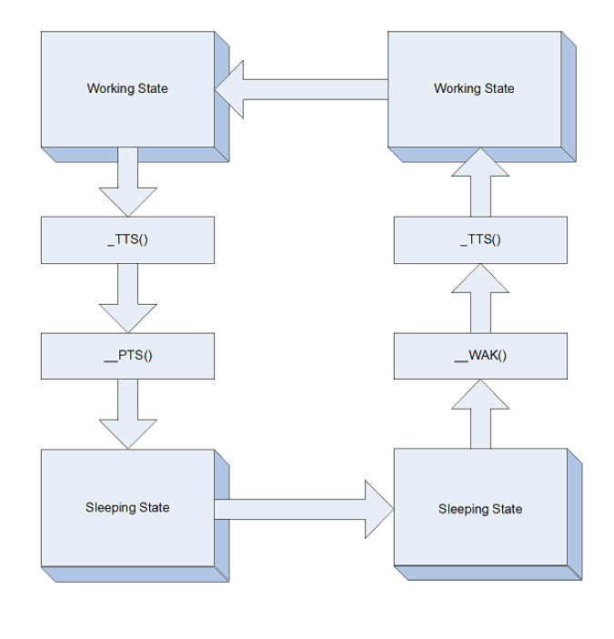
Fig. 7.1 Working / Sleeping State object evaluation flow