16. Waking and Sleeping
ACPI defines a mechanism to transition the system between the working state (G0) and a sleeping state (G1) or the soft-off (G2) state. During transitions between the working and sleeping states, the context of the user’s operating environment is maintained. ACPI defines the quality of the G1 sleeping state by defining the system attributes of four types of ACPI sleeping states (S1, S2, S3, and S4). Each sleeping state is defined to allow implementations that can tradeoff cost, power, and wake latencies. Additionally, ACPI defines the sleeping states such that an ACPI platform can support multiple sleeping states, allowing the platform to transition into a particular sleeping state for a predefined period of time and then transition to a lower power/higher wake latency sleeping state (transitioning through the G0 state) (See note below).
OSPM uses the RTC wakeup feature or the Time and Alarm Namespace
device to program in the time transition delay. Prior to sleeping, OSPM
will program the alarm to the closest (in time) wakeup event: either a
transition to a lower power sleeping state, or a calendar event (to run
some application).
ACPI defines a programming model that provides a mechanism for OSPM to initiate the entry into a sleeping or soft-off state (S1-S5); this consists of a 3 bit field SLP_TYPx (See note below) that indicates the type of sleep state to enter, and a single control bit SLP_EN to start the sleeping process. On HW-reduced ACPI systems, the register described by the SLEEP_CONTROL_REG field in the FADT is used instead of the fixed SLP_TYPx and SLP_EN register bit fields.
Notice that there can be two fixed PM1x_CNT registers, each pointing
to a different system I/O space region. Normally a register grouping
only allows a bit or bit field to reside in a single register group
instance (a or b); however, each platform can have two instances of the
SLP_TYP (one for each grouping register: a and b). The \_Sx control
method gives a package with two values: the first is the SLP_TYPa value
and the second is the SLP_TYPb value.
Note
Systems containing processors without a hardware mechanism to place the processor in a low-power state may additionally require the execution of appropriate native instructions to place the processor in a low-power state after OSPM sets the SLP_EN bit. The hardware may implement a number of low-power sleeping states and then associate these states with the defined ACPI sleeping states (through the SLP_TYPx fields). The ACPI system firmware creates a sleeping object associated with each supported sleeping state (unsupported sleeping states are identified by the lack of the sleeping object). Each sleeping object contains two constant 3-bit values that OSPM will program into the SLP_TYPa and SLP_TYPb fields (in fixed register space), or, on HW-reduced ACPI platforms, a single 3-bit value that OSPM will write to the register specified by the FADT’s SLEEP_CONTROL_REG field.
On systems that are not HW-reduced ACPI platforms, an alternate mechanism for entering and exiting the S4 state is defined. This mechanism passes control to the platform runtime firmware to save and restore platform context. Context ownership is similar in definition to the S3 state, but hardware saves and restores the context of memory to non-volatile storage (such as a disk drive), and OSPM treats this as an S4 state with implied latency and power constraints. This alternate mechanism of entering the S4 state is referred to as the S4BIOS transition.
Prior to entering a sleeping state (S1-S4), OSPM will execute OEM-specific AML/ASL code contained in the _PTS (Prepare To Sleep) control method. One use of the _PTS control method is that it can indicate to the embedded controller what sleeping state the system will enter. The embedded controller can then respond by executing the proper power-plane sequencing upon sleep state entry.
The _WAK (Wake) control method is then executed. This control method again contains OEM-specific AML/ASL code. One use of the _WAK control method requests OSPM to check the platform for any devices that might have been added or removed from the system while the system was asleep. For example, a PC Card controller might have had a PC Card added or removed, and because the power to this device was off in the sleeping state, the status change event was not generated.
This section discusses the system initialization sequence of an ACPI-enabled platform. This includes the boot sequence, different wake scenarios, and an example to illustrate how to use the system address map reporting interfaces. This sequence is part of the ACPI event programming model.
Note
HW-reduced ACPI platforms do not implement the Legacy Mode nor the S4BIOS state described below.
For detailed information on the power management control methods described above, see Power and Performance Management
16.1. Sleeping States
The illustration below shows the transitions between the working state, the sleeping states, and the Soft Off state.
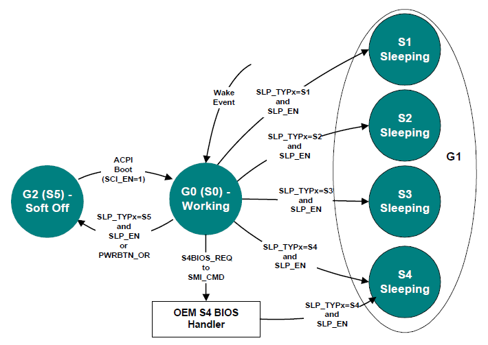
Fig. 16.1 Example Sleeping States
ACPI defines distinct differences between the G0 and G1 system states.
In the G0 state, work is being performed by the OS/application software and the hardware. The CPU or any particular hardware device could be in any one of the defined power states (C0-C3 or D0-D3); however, some work will be taking place in the system.
In the G1 state, the system is assumed to be doing no work. Prior to entering the G1 state, OSPM will place devices in a device power state compatible with the system sleeping state to be entered; if a device is enabled to wake the system, then OSPM will place these devices into the lowest Dx state from which the device supports wake. This is defined in the power resource description of that device object. This definition of the G1 state implies:
The CPUs execute no instructions in the G1 state.
Hardware devices are not operating (except possibly to generate a wake event).
If not HW-reduced, ACPI registers are affected as follows:
Wake event bits are enabled in the corresponding fixed or general-purpose registers according to enabled wake options.
PM1 control register is programmed for the desired sleeping state.
WAK_STS is set by hardware in the sleeping state.
All sleeping states have these specifications. ACPI defines additional attributes that allow an ACPI platform to have up to four different sleeping states, each of which has different attributes. The attributes were chosen to allow differentiation of sleeping states that vary in power, wake latency, and implementation cost tradeoffs.
Running processors at reduced levels of performance is not an ACPI sleeping state (G1); this is a working (G0) state-defined event.
The CPU cannot execute any instructions when in the sleeping state; OSPM relies on this fact. A platform designer might be tempted to support a sleeping system by reducing the clock frequency of the system, which allows the platform to maintain a low-power state while at the same time maintaining communication sessions that require constant interaction (as with some network environments). This is definitely a G0 activity where an OS policy decision has been made to turn off the user interface (screen) and run the processor in a reduced performance mode. This type of reduced performance state as a sleeping state is not defined by the ACPI specification; ACPI assumes no code execution during sleeping states.
ACPI defines attributes for four sleeping states: S1, S2, S3 and S4. (Notice that S4 and S5 are very similar from a hardware standpoint.) ACPI-compatible platforms can support multiple sleeping states. ACPI specifies that a 3-bit binary number be associated with each sleeping state (these numbers are given objects within ACPI’s root namespace: (\_S0, \_S1, \_S2, \_S3, \_S4 and \_S5). When entering a system sleeping state, OSPM will do the following:
Pick the deepest sleeping state supported by the platform and enabled waking devices.
Execute the _PTS control method (which passes the type of intended sleep state to OEM AML code).
If OS policy decides to enter the S4 state and chooses to use the S4BIOS mechanism and S4BIOS is supported by the platform, OSPM will pass control to the platform runtime firmware software by writing the S4BIOS_REQ value to the SMI_CMD port.
If not using the S4BIOS mechanism, OSPM gets the SLP_TYPx value from the associated sleeping object (\_S1, \_S2, \_S3, \_S4 or \_S5).
Program the SLP_TYPx fields with the values contained in the selected sleeping object.
Note
Compatibility — The _GTS method is deprecated in ACPI 5.0A. For earlier versions, execute the _GTS control method, passing an argument that indicates the sleeping state to be entered (1, 2, 3, or 4 representing S1, S2, S3, and S4).
If entering S1, S2, or S3, flush the processor caches.
If not entering S4BIOS, set the SLP_EN bit to start the sleeping sequence. (This actually occurs on the same write operation that programs the SLP_TYPx field in the PM1_CNT register.) If entering S4BIOS, write the S4BIOS_REQ value into the SMI_CMD port.
If HW-reduced, program the register indicated by the SLEEP_CONTROL_REG FADT field with the HW-reduced ACPI Sleep Type value (retrieved from the sleep state object in step 4 above) and with the SLP_EN bit set to one.
On systems containing processors without a hardware mechanism to place the processor in a low-power state, execute appropriate native instructions to place the processor in a low-power state.
The _PTS control method provides the platform runtime firmware a mechanism for performing some housekeeping, such as writing the sleep type value to the embedded controller, before entering the system sleeping state. Control method execution occurs “just prior” to entering the sleeping state and is not an event synchronized with the write to the PM1_CNT register. Execution can take place several seconds prior to the system actually entering the sleeping state. As such, no hardware power-plane sequencing takes place by execution of the _PTS control method.
Note
Compatibility — The _BFS method is deprecated in ACPI 5.0A. In earlier versions, on waking, the _BFS control method is executed. OSPM then executes the _WAK control method. This control method executes OEM-specific ASL/AML code that can search for any devices that have been added or removed during the sleeping state.*
The following sections describe the sleeping state attributes.
16.1.1. S1 Sleeping State
The S1 state is defined as a low wake-latency sleeping state. In this state, all system context is preserved with the exception of CPU caches. Before entering S1, OSPM will flush the system caches. If the platform supports the WBINVD instruction (as indicated by the WBINVD and WBINVD_FLUSH flags in the FADT), OSPM will execute the WBINVD instruction. The hardware is responsible for maintaining all other system context, which includes the context of the CPU, memory, and chipset.
Examples of S1 sleeping state implementation alternatives follow.
16.1.1.1. Example 1: S1 Sleeping State Implementation
This example references an IA processor that supports the stop grant state through the assertion of the STPCLK# signal. When SLP_TYPx is programmed to the S1 value (the OEM chooses a value, which is then placed in the \_S1 object) and the SLP_ENx bit is subsequently set, or when the HW-reduced ACPI Sleep Type value for S1 and the SLP_EN bit are written to the Sleep Control Register, the hardware can implement an S1 state by asserting the STPCLK# signal to the processor, causing it to enter the stop grant state.
In this case, the system clocks (PCI and CPU) are still running. Any enabled wake event causes the hardware to de-assert the STPCLK# signal to the processor whereby OSPM must first invalidate the CPU caches and then transition back into the working state.
16.1.1.2. Example 2: S1 Sleeping State Implementation
When SLP_TYPx is programmed to the S1 value and the SLP_ENx bit is subsequently set, or the HW-reduced ACPI Sleep Type value for S1 and the SLP_EN bit are written to the Sleep Control Register, the hardware will implement an S1 sleeping state transition by doing the following:
Placing the processor into the stop grant state.
Stopping the processor’s input clock, placing the processor into the stop clock state.
Placing system memory into a self-refresh or suspend-refresh state. Refresh is maintained by the memory itself or through some other reference clock that is not stopped during the sleeping state.
Stopping all system clocks (asserts the standby signal to the system PLL chip). Normally the RTC will continue running.
In this case, all clocks in the system have been stopped (except for the RTC). Hardware must reverse the process (restarting system clocks) upon any enabled wake event whereby OSPM must first invalidate the CPU caches and then transition back into the working state.
16.1.2. S2 Sleeping State
The S2 state is defined as a low wake latency sleep state. This state is similar to the S1 sleeping state where any context except for system memory may be lost. Additionally, control starts from the processor’s reset vector after the wake event. Before entering S2 the SLP_EN bit, OSPM will flush the system caches. If the platform supports the WBINVD instruction (as indicated by the WBINVD and WBINVD_FLUSH flags in the FADT), OSPM will execute the WBINVD instruction. The hardware is responsible for maintaining chip set and memory context. An example of an S2 sleeping state implementation follows.
16.1.2.1. Example: S2 Sleeping State Implementation
When the SLP_TYPx register(s) are programmed to the S2 value (found in the \_S2 object) and the SLP_EN bit is set, or the HW-reduced ACPI Sleep Type value for S2 and the SLP_EN bit are written to the Sleep Control Register, the hardware will implement an S2 sleeping state transition by doing the following:
Stopping system clocks (the only running clock is the RTC).
Placing system memory into a self-refresh or suspend-refresh state.
Powering off the CPU and cache subsystem.
From S2 Sleeping State the CPU is reset upon detection of the wake event; however, core logic and memory maintain their context. Execution control starts from the CPU’s boot vector. The platform boot firmware is required to:
Program the initial boot configuration of the CPU (such as the CPU’s MSR and MTRR registers).
Initialize the cache controller to its initial boot size and configuration.
Enable the memory controller to accept memory accesses.
Jump to the waking vector.
16.1.3. S3 Sleeping State
The S3 state is defined as a low wake-latency sleep state. From the software viewpoint, this state is functionally the same as the S2 state. The operational difference is that some Power Resources that may have been left ON in the S2 state may not be available to the S3 state. As such, some devices may be in a lower power state when the system is in S3 state than when the system is in the S2 state. Similarly, some device wake events can function in S2 but not S3. An example of an S3 sleeping state implementation follows.
16.1.3.1. Example: S3 Sleeping State Implementation
When the SLP_TYPx register(s) are programmed to the S3 value (found in the \_S3 object) and the SLP_EN bit is set, or the HW-reduced ACPI Sleep Type value for S3 and the SLP_EN bit are written to the Sleep Control Register, the hardware will implement an S3 sleeping state transition by doing the following:
Placing the memory into a low-power auto-refresh or self-refresh state.
Devices that are maintaining memory isolating themselves from other devices in the system.
Removing power from the system. At this point, only devices supporting memory are powered (possibly partially powered). The only clock running in the system is the RTC clock.
From S3 Sleeping State, the wake event repowers the system and resets most devices (depending on the implementation). Execution control starts from the CPU’s boot vector. The platform boot firmware is required to:
Program the initial boot configuration of the CPU (such as the MSR and MTRR registers).
Initialize the cache controller to its initial boot size and configuration.
Enable the memory controller to accept memory accesses.
Jump to the waking vector.
Notice that if the configuration of cache memory controller is lost while the system is sleeping, the platform boot firmware is required to reconfigure it to either the pre-sleeping state or the initial boot state configuration. The platform boot firmware can store the configuration of the cache memory controller into the reserved memory space, where it can then retrieve the values after waking. OSPM will call the _PTS method once per session (prior to sleeping).
The platform boot firmware is also responsible for restoring the memory controller’s configuration. If this configuration data is destroyed during the S3 sleeping state, then the platform boot firmware needs to store the pre-sleeping state or initial boot state configuration in a non-volatile memory area (as with RTC CMOS RAM) to enable it to restore the values during the waking process.
When OSPM re-enumerates buses coming out of the S3 sleeping state, it will discover any devices that have been inserted or removed, and configure devices as they are turned on.
16.1.4. S4 Sleeping State
The S4 sleeping state is the lowest-power, longest wake-latency sleeping state supported by ACPI. In order to reduce power to a minimum, it is assumed that the hardware platform has powered off all devices. Because this is a sleeping state, the platform context is maintained. Depending on how the transition into the S4 sleeping state occurs, the responsibility for maintaining system context changes. S4 supports two entry mechanisms: OS initiated and platform runtime firmware-initiated. The OSPM-initiated mechanism is similar to the entry into the S1-S3 sleeping states; OSPM driver writes the SLP_TYPx fields and sets the SLP_EN bit, or writes the HW-reduced ACPI Sleep Type value for S3 and the SLP_EN bit to the Sleep Control Register. The platform runtime firmware-initiated mechanism occurs by OSPM transferring control to the platform runtime firmware by writing the S4BIOS_REQ value to the SMI_CMD port, and is not supported on HW-reduced ACPI platforms.
In OSPM-initiated S4 sleeping state, OSPM is responsible for saving all system context. Before entering the S4 state, OSPM will save context of all memory as specified in System Address Map Interfaces.
Upon waking, OSPM shall then restore the system context. When OSPM re-enumerates buses coming out of the S4 sleeping state, it will discover any devices that have come and gone, and configure devices as they are turned on.
In the platform runtime firmware-initiated S4 sleeping state, OSPM is responsible for the same system context as described in the S3 sleeping state (platform runtime firmware restores the memory and some chip set context). The S4BIOS transition transfers control to the platform runtime firmware, allowing it to save context to non-volatile memory (such as a disk partition).
16.1.4.1. Operating System-Initiated S4 Transition
If OSPM supports OSPM-initiated S4 transition, it will not generate a platform firmware-initiated S4 transition. Platforms that support the platform firmware-initiated S4 transition also support OSPM-initiated S4 transition.
OSPM-initiated S4 transition is initiated by OSPM by saving system context, writing the appropriate values to the SLP_TYPx register(s), and setting the SLP_EN bit, or writes the HW-reduced ACPI Sleep Type value for S4 and the SLP_EN bit to the Sleep Control Register. Upon exiting the S4 sleeping state, the platform boot firmware restores the chipset to its POST condition, updates the hardware signature (described later in this section), and passes control to OSPM through a normal boot process.
When the platform boot firmware builds the ACPI tables, it generates a hardware signature for the system. If the hardware configuration has changed during an OS-initiated S4 transition and it changes the content or structure of the ACPI tables, the platform boot firmware updates the hardware signature in the FACS table as described in Section 5.2.10 (Firmware ACPI Control Structure (FACS)).
Upon waking, in order to locate the hardware signature, the physical address of the RSDP must be reacquired via methods described in 5.2.5.1 (Finding the RSDP on IA-PC Systems) or 5.2.5.2 (Finding the RSDP on UEFI Enable Systems) and therefore it must not be assumed that the FACS and its Hardware Signature would be located in the same physical memory address as the prior boot.
16.1.4.2. The S4BIOS Transition
This transition is not supported on HW-reduced ACPI platforms. On other systems, the platform runtime firmware-initiated S4 transition begins with OSPM writing the S4BIOS_REQ value into the SMI_CMD port (as specified in the FADT). Once gaining control, the platform runtime firmware then saves the appropriate memory and chip set context, and then places the platform into the S4 state (power off to all devices).
In the FACS memory table, there is the S4BIOS_F bit that indicates hardware support for the platform runtime firmware-initiated S4 transition. If the hardware platform supports the S4BIOS state, it sets the S4BIOS_F flag within the FACS memory structure prior to booting the OS. If the S4BIOS_F flag in the FACS table is set, this indicates that OSPM can request the platform runtime firmware to transition the platform into the S4BIOS sleeping state by writing the S4BIOS_REQ value (found in the FADT) to the SMI_CMD port (identified by the SMI_CMD value in the FADT).
Upon waking the platform boot firmware restores memory context and jumps to the waking vector (similar to wake from an S3 state). Coming out of the S4BIOS state, the platform boot firmware must only configure boot devices (so it can read the disk partition where it saved system context). When OSPM re-enumerates buses coming out of the S4BIOS state, it will discover any devices that have come and gone, and configure devices as they are turned on.
16.1.5. S5 Soft Off State
OSPM places the platform in the S5 soft off state to achieve a logical off. Notice that the S5 state is not a sleeping state (it is a G2 state) and no context is saved by OSPM or hardware but power may still be applied to parts of the platform in this state, and, as such, it is not safe to disassemble. Also notice that from a hardware perspective, the S4 and S5 states are nearly identical. When initiated, the hardware will sequence the system to a state similar to the off state. The hardware has no responsibility for maintaining any system context (memory or I/O); however, it does allow a transition to the S0 state due to a power button press or a Remote Start. Upon start-up, the platform boot firmware performs a normal power-on reset, loads the boot sector, and then executes (but not the waking vector, as all ACPI table context is lost when entering the S5 soft off state).
The _TTS control method allows the platform runtime firmware a mechanism for performing some housekeeping, such as storing the targeted sleep state in a “global” variable that is accessible by other control methods (such as _PS3 and _DSW).
16.1.6. Transitioning from the Working to the Sleeping State
On a transition of the system from the working to the sleeping state, the following occurs:
OSPM decides (through a policy scheme) to place the system into the sleeping state.
OSPM invokes the _TTS method to indicate the deepest possible system state the system will transition to (1, 2, 3, or 4 representing S1, S2, S3, and S4).
OSPM examines all devices enabled to wake the system and determines the deepest possible sleeping state the system can enter to support the enabled wake functions. The _PRW named object under each device is examined, as well as the power resource object it points to.
OSPM places all device drivers into their respective Dx state. If the device is enabled for wake, it enters the Dx state associated with the wake capability. If the device is not enabled to wake the system, it enters the D3 state.
OSPM executes the _PTS control method, passing an argument that indicates the desired sleeping state (1, 2, 3, or 4 representing S1, S2, S3, and S4).
OSPM saves any other processor’s context (other than the local processor) to memory.
OSPM writes the waking vector into the FACS table in memory.
Note
Compatibility — The _GTS method is deprecated in ACPI 5.0A. For earlier versions, OSPM executes the _GTS control method, passing an argument that indicates the sleeping state to be entered (1, 2, 3, or 4 representing S1, S2, S3, and S4).*
If not a HW-reduced ACPI platform, OSPM clears the WAK_STS in the PM1a_STS and PM1b_STS registers. On HW-reduced ACPI platforms, OSPM clears the WAK_STS bit in the Sleep Status Register.
OSPM saves the local processor’s context to memory.
OSPM flushes caches (only if entering S1, S2 or S3).
OSPM sets GPE enable registers or enables wake-capable interrupts to ensure that all appropriate wake signals are armed.
If entering an S4 state using the S4BIOS mechanism, OSPM writes the S4BIOS_REQ value (from the FADT) to the SMI_CMD port. This passes control to the platform runtime firmware, which then transitions the platform into the S4BIOS state.
If not entering an S4BIOS state, and not a HW-reduced ACPI platform, then OSPM writes SLP_TYPa (from the associated sleeping object) with the SLP_ENa bit set to the PM1a_CNT register.
OSPM writes SLP_TYPb with the SLP_EN bit set to the PM1b_CNT register, or writes the HW-reduced ACPI Sleep Type value and the SLP_EN bit to the Sleep Control Register.
On systems containing processors without a hardware mechanism to place the processor in a low-power state, OSPM executes appropriate native instructions to place the processor in a low-power state.
OSPM loops on the WAK_STS bit, either in both the PM1a_CNT and PM1b_CNT registers, or in the SLEEP_STATUS_REG, in the case of HW-reduced ACPI platforms.
The system enters the specified sleeping state.
Note
This is accomplished after step 14 or 15 above.
16.1.7. Transitioning from the Working to the Soft Off State
On a transition of the system from the working to the soft off state, the following occurs:
OSPM executes the _PTS control method, passing the argument 5.
OSPM prepares its components to shut down (flushing disk caches).
Note
Compatibility — The _GTS method is deprecated in ACPI 5.0A. For earlier versions, OSPM executes the _GTS control method, passing the argument 5.
If not a HW-reduced ACPI platform, OSPM writes SLP_TYPa (from the \_S5 object) with the SLP_ENa bit set to the PM1a_CNT register.
OSPM writes SLP_TYPb (from the \_S5 object) with the SLP_ENb bit set to the PM1b_CNT register, or writes the HW-reduced ACPI Sleep Type value for S5 and the SLP_EN bit to the Sleep Control Register.
The system enters the Soft Off state.
16.2. Flushing Caches
Before entering the S1, S2 or S3 sleeping states, OSPM is responsible for flushing the system caches. ACPI provides a number of mechanisms to flush system caches. These include:
Using a native instruction (for example, the IA-32 architecture WBINVD instruction) to flush and invalidate platform caches.
WBINVD_FLUSH flag set (1) in the FADT indicates the system provides this support level.
Using the IA-32 instruction WBINVD to flush but not invalidate the platform caches.
WBINVD flag set (1) in the FADT indicates the system provides this support level.
The manual flush mechanism has two caveats:
Largest cache is 1 MB in size (FLUSH_SIZE is a maximum value of 2 MB).
No victim caches (for which the manual flush algorithm is unreliable).
Processors with built-in victim caches will not support the manual flush mechanism and are therefore required to support the WBINVD mechanism to use the S2 or S3 state.
The manual cache-flushing mechanism relies on the two FADT fields:
FLUSH_SIZE. Indicates twice the size of the largest cache in bytes.
FLUSH_STRIDE. Indicates the smallest line size of the caches in bytes.
The cache flush size value is typically twice the size of the largest cache size, and the cache flush stride value is typically the size of the smallest cache line size in the platform. OSPM will flush the system caches by reading a contiguous block of memory indicated by the cache flush size.
16.3. Initialization
This section covers the initialization sequences for an ACPI platform. After a reset or wake from an S2, S3, or S4 sleeping state (as defined by the ACPI sleeping state definitions), the CPU will start execution from its boot vector. At this point, the initialization software has many options, depending on what the hardware platform supports. This section describes at a high level what should be done for these different options. The figure below illustrates the flow of the boot-up software.
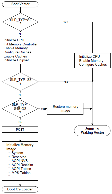
Fig. 16.2 Platform Firmware Initialization
The processor will start executing at its power-on reset vector when waking from an S2, S3, or S4 sleeping state, during a power-on sequence, or as a result of a hard or soft reset.
When executing from the power-on reset vector as a result of a power-on sequence, a hard or soft reset, or waking from an S4 sleep state, the platform firmware performs complete hardware initialization; placing the system in a boot configuration. The firmware then passes control to the operating system boot loader.
When executing from the power-on reset vector as a result of waking from an S2 or S3 sleep state, the platform firmware performs only the hardware initialization required to restore the system to either the state the platform was in prior to the initial operating system boot, or to the pre-sleep configuration state. In multiprocessor systems, non-boot processors should be placed in the same state as prior to the initial operating system boot. The platform firmware then passes control back to OSPM system by jumping to either the Firmware_Waking_Vector or the X_Firmware_Waking_Vector in the FACS (see Firmware ACPI Control Structure (FACS) for more information). The contents of operating system memory contents may not be changed during the S2 or S3 sleep state.
First, the platform runtime firmware determines whether this is a wake from S2 or S3 by examining the SLP_TYP register value, which is preserved between sleeping sessions. If this is an S2 or S3 wake, then the platform runtime firmware restores minimum context of the system before jumping to the waking vector. This includes:
- CPU configuration.
Platform runtime firmware restores the pre-sleep configuration or initial boot configuration of each CPU (MSR, MTRR, firmware update, SMBase, and so on). Interrupts must be disabled (for IA-32 processors, disabled by CLI instruction).
- Memory controller configuration.
the configuration is lost during the sleeping state, the platform runtime firmware initializes the memory controller to its pre-sleep configuration or initial boot configuration.
- Cache memory configuration.
If the configuration is lost during the sleeping state, the platform runtime firmware initializes the cache controller to its pre-sleep configuration or initial boot configuration.
- Functional device configuration.
The platform runtime firmware doesn’t need to configure/restore context of functional devices such as a network interface (even if it is physically included in chipset) or interrupt controller. OSPM is responsible for restoring all context of these devices. The only requirement for the hardware and platform runtime firmware is to ensure that interrupts are not asserted by devices when the control is passed to OS.
- ACPI registers.
SCI_EN bit must be set on non-HW-reduced ACPI platforms, and all event status/enable bits (PM1x_STS, PM1x_EN, GPEx_STS and GPEx_EN) must not be changed by platform runtime firmware.
Note
The platform runtime firmware may reconfigure the CPU, memory controller, and cache memory controller to either the pre-sleeping configuration or the initial boot configuration. OSPM must ccommodate both configurations.
When waking from an S4BIOS sleeping state, the platform boot firmware initializes a minimum number of devices such as CPU, memory, cache, chipset and boot devices. After initializing these devices, the platform boot firmware restores memory context from non-volatile memory such as hard disk, and jumps to waking vector.
As mentioned previously, waking from an S4 state is treated the same as a cold boot: the platform boot firmware runs POST and then initializes memory to contain the ACPI system description tables. After it has finished this, it can call OSPM loader, and control is passed to OSPM.
When waking from S4 (either S4OS or S4BIOS), the platform boot firmware may optionally set SCI_EN bit before passing control to OSPM. In this case, interrupts must be disabled (for IA-32 processors, disabled CLI instruction) until the control is passed to OSPM and the chipset must be configured in ACPI mode.
16.3.1. Placing the System in ACPI Mode
When a platform initializes from a cold boot (mechanical off or from an S4 or S5 state), the hardware platform may be configured in a legacy configuration, if not a HW-reduced ACPI platform. From these states, the platform boot firmware software initializes the computer as it would for a legacy operating system. When control is passed to the operating system, OSPM will check the SCI_EN bit and if it is not set will then enable ACPI mode by first finding the ACPI tables, and then by generating a write of the ACPI_ENABLE value to the SMI_CMD port (as described in the FADT). The hardware platform will set the SCI_EN bit to indicate to OSPM that the hardware platform is now configured for ACPI.
Note
Before SCI is enabled, no SCI interrupt can occur. Nor can any SCI interrupt occur immediately after ACPI is on. The SCI interrupt can only be signaled after OSPM has enabled one of the GPE/PM1 enable bits.
When the platform is waking from an S1, S2 or S3 state, and from S4 and S5 on HW-reduced ACPI platforms, OSPM assumes the hardware is already in the ACPI mode and will not issue an ACPI_ENABLE command to the SMI_CMD port
16.3.2. Platform Boot Firmware Initialization of Memory
During a power-on reset, an exit from an S4 sleeping state, or an exit from an S5 soft-off state, the platform boot firmware needs to initialize memory. This section explains how the platform boot firmware should configure memory for use by a number of features including:
ACPI tables.
Platform firmware memory that wants to be saved across S4 sleeping sessions and should be cached.
Platform firmware memory that does not require saving and should be cached.
For example, the configuration of the platform’s cache controller requires an area of memory to store the configuration data. During the wake sequence, the platform boot firmware will re-enable the memory controller and can then use its configuration data to reconfigure the cache controllers. To support these three items, IA-PC-based systems contain System Address Map Interfaces that return the following memory range types:
- ACPI Reclaim Memory.
Memory identified by the platform boot firmware that contains the ACPI tables. This memory can be any place above 8 MB and contains the ACPI tables. When OSPM is finished using the ACPI tables, it is free to reclaim this memory for system software use (application space).
- ACPI Non-Volatile-Sleeping Memory (NVS).
Memory identified by the BIOS as being reserved by the platform boot firmware for its use. OSPM is required to tag this memory as cacheable, and to save and restore its image before entering an S4 state. Except as directed by control methods, OSPM is not allowed to use this physical memory. OSPM will call the _PTS control method some time before entering a sleeping state, to allow the platform’s AML code to update this memory image before entering the sleeping state. After the system awakes from an S4 state, OSPM will restore this memory area and call the _WAK control method to enable the platform boot firmware to reclaim its memory image.
Note
The memory information returned from the system address map reporting interfaces should be the same before and after an S4 sleep.
When the system is first booting, OSPM will invoke E820 interfaces on IA-PC-based legacy systems or the GetMemoryMap() interface on UEFI-enabled systems to obtain a system memory map, System Address Map Interfaces for more information). As an example, the following memory map represents a typical IA-PC-based legacy platform’s physical memory map.
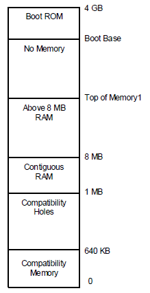
Fig. 16.3 Example Physical Memory Map
The names and attributes of the different memory regions are listed below:
0-640 KB. Compatibility Memory. Application executable memory for an 8086 system.
640 KB-1 MB. Compatibility Holes. Holes within memory space that allow accesses to be directed to the PC-compatible frame buffer (A0000h-BFFFFh), to adapter ROM space (C0000h-DFFFFh), and to system platform firmware space (E0000h-FFFFFh).
1 MB-8 MB. Contiguous RAM. An area of contiguous physical memory addresses. Operating systems may require this memory to be contiguous in order for its loader to load the OS properly on boot up. (No memory-mapped I/O devices should be mapped into this area.)
8 MB-Top of Memory1. This area contains memory to the “top of memory1” boundary. In this area, memory-mapped I/O blocks are possible.
Boot Base-4 GB. This area contains the bootstrap ROM.
The platform boot firmware should decide where the different memory structures belong, and then configure the E820 handler to return the appropriate values.
For this example, the platform boot firmware will report the system memory map by E820 as shown in Figure 15-4. Notice that the memory range from 1 MB to top of memory is marked as system memory, and then a small range is additionally marked as ACPI reclaim memory. A legacy OS that does not support the E820 extensions will ignore the extended memory range calls and correctly mark that memory as system memory.
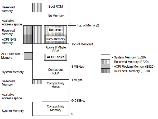
Fig. 16.4 Memory as Configured after Boot
Also, from the Top of Memory1 to the Top of Memory2, the platform boot firmware has set aside some memory for its own use and has marked as reserved both ACPI NVS Memory and Reserved Memory. A legacy OS will throw out the ACPI NVS Memory and correctly mark this as reserved memory (thus preventing this memory range from being allocated to any add-in device).
OSPM will call the _PTS control method prior to initiating a sleep (by programming the sleep type, followed by setting the SLP_EN bit). During a catastrophic failure (where the integrity of the AML code interpreter or driver structure is questionable), if OSPM decides to shut the system off, it will not issue a _PTS, but will immediately issue a SLP_TYP of “soft off” and then set the SLP_EN bit, or directly write the HW-reduced ACPI Sleep Type value and the SLP_EN bit to the Sleep Control Register. Hence, the hardware should not rely solely on the _PTS control method to sequence the system to the “soft off” state. After waking from an S4 state, OSPM will restore the ACPI NVS memory image and then issue the _WAK control method that informs platform runtime firmware that its memory image is back.
16.3.3. OS Loading
At this point, the platform boot firmware has passed control to OSPM, either by using OSPM boot loader (a result of waking from an S4/S5 or boot condition) or OSPM waking vector (a result of waking from an S2 or S3 state). For the Boot OS Loader path, OSPM will get the system address map via one of the mechanisms describe in System Address Map Interfaces If OSPM is booting from an S4 state, it will then check the NVS image file’s hardware signature with the hardware signature within the FACS table (built by platform boot firmware) to determine whether it has changed since entering the sleeping state (indicating that the platforms fundamental hardware configuration has changed during the current sleeping state). If the signature has changed, OSPM will not restore the system context and can boot from scratch (from the S4 state). Next, for an S4 wake, OSPM will check the NVS file to see whether it is valid. If valid, then OSPM will load the NVS image into system memory. Next, if not a HW-reduced ACPI platform, OSPM will check the SCI_EN bit and if it is not set, will write the ACPI_ENABLE value to the SMI_CMD register to switch into the system into ACPI mode and will then reload the memory image from the NVS file.
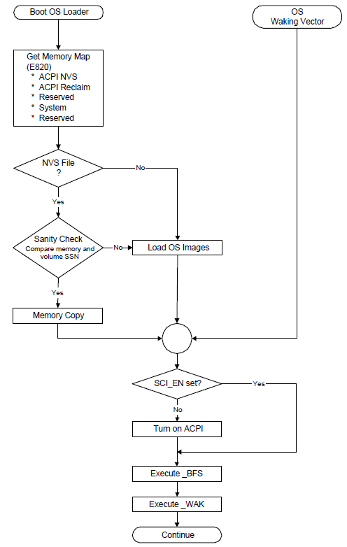
Fig. 16.5 OS Initialization
If an NVS image file did not exist, then OSPM loader will load OSPM from scratch. At this point, OSPM will generate a _WAK call that indicates to the platform runtime firmware that its ACPI NVS memory image has been successfully and completely updated.
16.3.4. Exiting ACPI Mode
For machines that do not boot in ACPI mode, ACPI provides a mechanism that enables the OS to disable ACPI. The following occurs:
OSPM unloads all ACPI drivers (including the ACPI driver).
OSPM disables all ACPI events.
OSPM finishes using all ACPI registers.
OSPM issues an I/O access to the port at the address contained in the SMI_CMD field (in the FADT) with the value contained in the ACPI_DISABLE field (in the FADT).
Platform runtime firmware then remaps all SCI events to legacy events and resets the SCI_EN bit.
Upon seeing the SCI_EN bit cleared, the ACPI OS enters the legacy OS mode.
When and if the legacy OS returns control to the ACPI OS, if the legacy OS has not maintained the ACPI tables (in reserved memory and ACPI NVS memory), the ACPI OS will reboot the system to allow the platform runtime firmware to re-initialize the tables.